Download to read offline

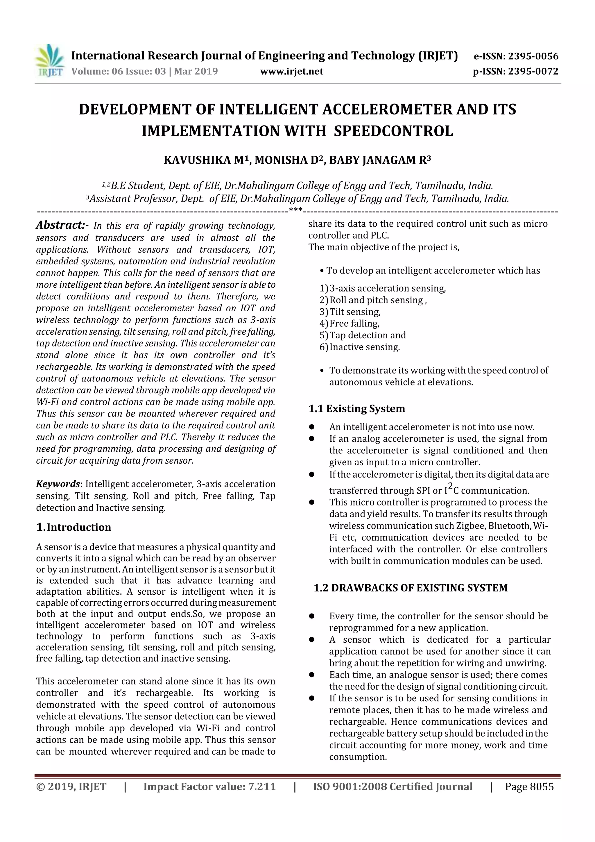
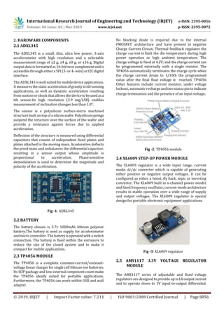
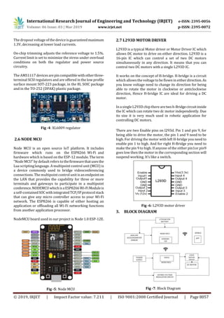
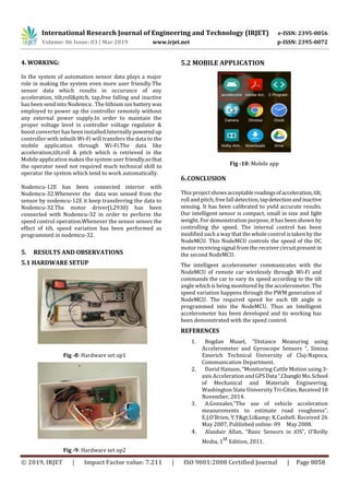

This document describes the development of an intelligent accelerometer that can perform various sensing functions and communicate wirelessly. The accelerometer is intended to reduce the need for separate programming and circuit design for sensor data acquisition. It uses an ADXL345 accelerometer, lithium polymer battery, TP4056 charging module, XL6009 boost converter, AMS1117 voltage regulator, and NodeMCU microcontroller. The accelerometer's functions include 3-axis acceleration sensing, tilt sensing, roll and pitch sensing, free fall detection, tap detection, and inactivity sensing. It is made intelligent by integrating these sensing capabilities along with wireless communication and recharging abilities. The document demonstrates its use for autonomous vehicle speed control based on sensor readings.