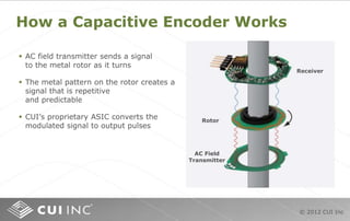
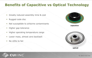
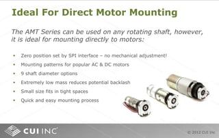
SlideShare a Scribd company logo
© 2012 CUI Inc
AMT203 Absolute Encoder
© 2012 CUI Inc
Contents
Purpose
The purpose of this training module is to familiarize you with rotary absolute
encoders and show the benefits of the AMT203.
Objectives
 Describe the functional theory of encoders; specifically absolute encoders
 Understand what makes the AMT203 revolutionary
 Explain the different components that make up the AMT203
 Describe the installation and assembly of the AMT203
 Illustrate the flexible options available with the AMT203
Content: 23 pages
Learning time: 15 minutes
© 2012 CUI Inc
What Is An Encoder?
© 2012 CUI Inc
How An Encoder Functions
© 2012 CUI Inc
Encoders Provide Directional Information
In this example, Signal A leads
B, i.e., Signal A outputs a rising
edge before Signal B. This
indicates the shaft is rotating
counter-clockwise.
In this example, Signal B leads
A. This indicates the shaft is
rotating clockwise.
Signal A
Signal B
Signal A
Signal B
Signal A leads signal B
Signal B leads signal A
© 2012 CUI Inc
Encoders Provide Position Information
© 2012 CUI Inc
Encoders Provide Speed Information
Encoders can detect speed when the number of output pulses is counted in a
specified time span. The time element is typically provided by an internal
oscillator or clock. The number of pulses in one revolution must also be known.
The equation for calculating speed is:
C
PPR
S =
t
60
÷
Where "S" is speed in rpm, "C" is the number of pulses counted in a "t" time
interval. If 60 pulses were counted in 10 seconds from a 360PPR encoder, the
speed can be calculated:
S = = 0.1666 ÷ 0.1666 = 1 rpm60
360
10
60
÷
All of the counting, timing and calculations can be done electronically
in real time and used to monitor or control speed.
© 2012 CUI Inc
Encoders Provide Distance Information
C = L ÷ (p * D) * PPR
C = 12 ÷ (3.142 * 8) * 2000 = 955
Pulse count to achieve desired linear travel can be calculated in a similar fashion for
devices that use ball screws, gears or pulleys to convert rotary motion to linear travel.
© 2012 CUI Inc
Quadrature Decoding
Quadrature decoder circuit
Channel A
Channel B
Quad A pulses
Quad B pulses
One cycle
1 42 3
© 2012 CUI Inc
What Is An Absolute Encoder?
Absolute encoder output
1 7 15 31 63
20
21
22
23
24
25
1
0
0
0
0
0
1
1
1
0
0
0
1
1
1
1
0
0
1
1
1
1
1
0
1
1
1
1
1
1
Incremental encoder output
1
2
4
8
16
32
0
0
1
0
1
1
0
1
Bit
Bit
Value
© 2012 CUI Inc
Where Are Encoders Used?
elevators factory aircraft automobiles
satellites
mobile equipment
medical devices machine tools
pick and place
process automation
packaging
automation
industrial robots
© 2012 CUI Inc
Types of Rotary Encoders
Mechanical
24 (16) – 28 (256)
Optical
28 (256) – 219 (524,287)
Magnetic
28 (256) – 217 (131,071)
28 (256) – 213 (8,192) 212 (4,096)
Fiber Optic Capacitive
© 2012 CUI Inc
How a Capacitive Encoder Works
Receiver
Rotor
AC Field
Transmitter
 AC field transmitter sends a signal
to the metal rotor as it turns
 The metal pattern on the rotor creates a
signal that is repetitive
and predictable
 CUI’s proprietary ASIC converts the
modulated signal to output pulses
© 2012 CUI Inc
Benefits of Capacitive vs Optical Technology
capacitive
optical
 Greatly reduced assembly time & cost
 Rugged code disc
 Not susceptible to airborne contaminants
 Higher gap tolerance
 Higher operating temperature range
 Lower mass, almost zero backlash
 No LEDs to fail
© 2012 CUI Inc
AMT203 Specification and Feature Highlights
 High resolution- 12-bit (4,096 PPR)
 Broad temperature range- -25 – +85° C
 Incremental option- A/B quadrature option for >8,000 RPM
 Low profile- 11 mm depth
 Light-weight mechanical design- 15g net weight (0.53 oz.)
 Low current consumption than optical- <10 mA
 Programmable zero position- saves time and money
 Robust design- capacitive technology not susceptible to dust and particulates
 Adapts to 9 common shaft diameters- allows for a high level of flexibility
© 2012 CUI Inc
Ideal For Direct Motor Mounting
The AMT Series can be used on any rotating shaft, however,
it is ideal for mounting directly to motors:
 Zero position set by SPI interface – no mechanical adjustment!
 Mounting patterns for popular AC & DC motors
 9 shaft diameter options
 Extremely low mass reduces potential backlash
 Small size fits in tight spaces
 Quick and easy mounting process
© 2012 CUI Inc
Easy Assembly And Installation
Assembly of the AMT203 requires minimal time and effort.
With just a few durable pieces, it snaps together in seconds without risk of
damaging a glass optical disk or other fragile components.
© 2012 CUI Inc
AMT203 Assembly
Double-click on the illustration below to view a
short AMT assembly video.
© 2012 CUI Inc
Versatile Shaft And Mounting Options
mounting patterns
Using the shaft adapter and the 9 color-coded
sleeves, both the AMT203 can be adapted to 9
different motor shaft sizes.
This is done by snapping one of the sleeves into
the shaft adapter.
Shaft adapter & sleeves
hole pattern
mm/in
# of
holes
hole
size
Ø16/0.63 2 M1.6
Ø19.05/0.75 2 #4
Ø21.45/0.844 3 M1.6 or M2
Ø25.4/1.0 4 M1.6 or M2
Shaft Adapter
Sleeves
shaft sleeves
Ø2 mm
Ø3 mm
Ø1/8 in
Ø3/16 in
Ø4mm
Ø5 mm
Ø6 mm
Ø1/4 in
Ø8 mm
© 2012 CUI Inc
AMT203 Demo Board
With the AMT203 Demo Board you can:
 Set zero position
 Monitor shaft position
 Set CW or CCW for count increase/decrease
 Select HEX or DECIMAL position display
 Select incremental (A/B) or counter (STB/UDN) output
 Access/read/write 128 bytes of user EEPROM
 Experiment with all encoder functions
© 2012 CUI Inc
Serial Peripheral Interface
SCLK
MOSI
MISO
SS
Master Slave
SCLK
MISO
MOSI
Example of SPI Mode 1,1
Note that the data only changes on the falling edge
of SCK and is only read on the rising edge of SCK.
0 0 0 01 1 1 1
Advantages of SPI:
 Very fast >10 MHz
 Simple protocol (easy to program)
 Simple interface (no bidirectional pins)
 Supports full duplex data streaming
SPI is a Master-Slave protocol
 The Master device controls the clock (SCK)
 No data is transferred unless a clock signal is present
 All slaves are controlled by the master clock
 The slave devices may not manipulate the clock
SPI is a Data Exchange protocol
 As data is being clocked out, new data is clocked in
 Data is exchanged - no device can transmit only or receive only
 The master controls the exchange through the clock line (SCK)
SPI is a Synchronous protocol
 The data is clocked along with a clock signal (SCK)
 The clock signal controls data I/O and read
 Since SPI is synchronous, the clock rate can
 Vary, unlike RS-232 style communications
Features of SPI:
© 2012 CUI Inc
AMT203 Purchasing
 AMT203 encoder
 Shaft adaptor and 9 sleeves
 Centering tool
 Spacing tool
AMT203-V kit includes: AMT203-DMK includes:
 AMT203 demo board
 AMT203-V encoder kit
 USB cable
 Board to encoder interface cable
 Power supply
 Flash drive with drivers
View AMT203-DMK
View AMT203-V
© 2012 CUI Inc
www.cui.com/AMT_Modular_Encoders

More Related Content

What's hot

PLC LADDER DIAGRAM
PLC LADDER DIAGRAMPLC LADDER DIAGRAM
PLC LADDER DIAGRAM
Shruti Bhatnagar Dasgupta
 
Scada ppt
Scada  pptScada  ppt
Scada ppt
AKANSHA GURELE
 
ppt on PLC.pptx
ppt on  PLC.pptxppt on  PLC.pptx
ppt on PLC.pptx
Ajaykumar388421
 
Stepper motor in industrial applications
Stepper motor in industrial applicationsStepper motor in industrial applications
Stepper motor in industrial applications
Dr.Raja R
 
Dc motor
Dc motorDc motor
Dc motor
Sayyed Raza
 
Servo motor and servo drive
Servo motor and servo driveServo motor and servo drive
Servo motor and servo drive
Sai Kumar
 
Variable frequency drives
Variable frequency drivesVariable frequency drives
Variable frequency drives
Naveen Sihag
 
Optical Encoders
Optical EncodersOptical Encoders
Optical Encoders
Premier Farnell
 
Plc ppt
Plc pptPlc ppt
Plc ppt
Shehda Seifan
 
Chapter 8 Root Locus Techniques
Chapter 8 Root Locus TechniquesChapter 8 Root Locus Techniques
Chapter 8 Root Locus Techniques
guesta0c38c3
 
Choppers
ChoppersChoppers
Variable frequency drive working and operation
Variable frequency drive working and operationVariable frequency drive working and operation
Variable frequency drive working and operation
Sai Kumar
 
Bluetooth controlled robot
Bluetooth controlled robotBluetooth controlled robot
Bluetooth controlled robot
UVSofts Technologies
 
INTRODUCTION TO LVDT,RVDT and Potentiometer
INTRODUCTION TO LVDT,RVDT and Potentiometer INTRODUCTION TO LVDT,RVDT and Potentiometer
INTRODUCTION TO LVDT,RVDT and Potentiometer
SACHINNikam39
 
Dc servo motor
Dc servo motorDc servo motor
Dc servo motor
Jeegnesh Solanki
 
Stepper motor
Stepper motorStepper motor
Stepper motor
Anurag Chaudhary
 
Vfd
VfdVfd
Unit 2 servo motor
Unit 2 servo motorUnit 2 servo motor
Unit 2 servo motor
Er.Meraj Akhtar
 
Electrical drives lectures
Electrical drives lecturesElectrical drives lectures
Electrical drives lectures
PRABHAHARAN429
 
Introduction to vfd
Introduction to vfdIntroduction to vfd
Introduction to vfd
rrsurani
 

What's hot (20)

PLC LADDER DIAGRAM
PLC LADDER DIAGRAMPLC LADDER DIAGRAM
PLC LADDER DIAGRAM
 
Scada ppt
Scada  pptScada  ppt
Scada ppt
 
ppt on PLC.pptx
ppt on  PLC.pptxppt on  PLC.pptx
ppt on PLC.pptx
 
Stepper motor in industrial applications
Stepper motor in industrial applicationsStepper motor in industrial applications
Stepper motor in industrial applications
 
Dc motor
Dc motorDc motor
Dc motor
 
Servo motor and servo drive
Servo motor and servo driveServo motor and servo drive
Servo motor and servo drive
 
Variable frequency drives
Variable frequency drivesVariable frequency drives
Variable frequency drives
 
Optical Encoders
Optical EncodersOptical Encoders
Optical Encoders
 
Plc ppt
Plc pptPlc ppt
Plc ppt
 
Chapter 8 Root Locus Techniques
Chapter 8 Root Locus TechniquesChapter 8 Root Locus Techniques
Chapter 8 Root Locus Techniques
 
Choppers
ChoppersChoppers
Choppers
 
Variable frequency drive working and operation
Variable frequency drive working and operationVariable frequency drive working and operation
Variable frequency drive working and operation
 
Bluetooth controlled robot
Bluetooth controlled robotBluetooth controlled robot
Bluetooth controlled robot
 
INTRODUCTION TO LVDT,RVDT and Potentiometer
INTRODUCTION TO LVDT,RVDT and Potentiometer INTRODUCTION TO LVDT,RVDT and Potentiometer
INTRODUCTION TO LVDT,RVDT and Potentiometer
 
Dc servo motor
Dc servo motorDc servo motor
Dc servo motor
 
Stepper motor
Stepper motorStepper motor
Stepper motor
 
Vfd
VfdVfd
Vfd
 
Unit 2 servo motor
Unit 2 servo motorUnit 2 servo motor
Unit 2 servo motor
 
Electrical drives lectures
Electrical drives lecturesElectrical drives lectures
Electrical drives lectures
 
Introduction to vfd
Introduction to vfdIntroduction to vfd
Introduction to vfd
 

Similar to Absolute

9346f1488e08c541a68f7542d4649dee4f4e37b5.pdf
9346f1488e08c541a68f7542d4649dee4f4e37b5.pdf9346f1488e08c541a68f7542d4649dee4f4e37b5.pdf
9346f1488e08c541a68f7542d4649dee4f4e37b5.pdf
Marcellino Mandala
 
Applied motion products si2035 datasheet
Applied motion products si2035 datasheetApplied motion products si2035 datasheet
Applied motion products si2035 datasheet
Electromate
 
QuickSilver Controls QCI-DS031 QCI-N2-IX
QuickSilver Controls QCI-DS031 QCI-N2-IXQuickSilver Controls QCI-DS031 QCI-N2-IX
QuickSilver Controls QCI-DS031 QCI-N2-IX
Electromate
 
WIRELESS SURVILLANCE ROBOT
WIRELESS SURVILLANCE ROBOT WIRELESS SURVILLANCE ROBOT
WIRELESS SURVILLANCE ROBOT
KrishGupta94
 
QuickSilver Controls QCI-DS032 QCI-N2-MX
QuickSilver Controls QCI-DS032 QCI-N2-MXQuickSilver Controls QCI-DS032 QCI-N2-MX
QuickSilver Controls QCI-DS032 QCI-N2-MX
Electromate
 
Embedded system
Embedded systemEmbedded system
Embedded system
VishwasJangra
 
project 3 full report
project 3 full reportproject 3 full report
project 3 full report
Shubham Shivhare
 
Introduction to Arduino
Introduction to ArduinoIntroduction to Arduino
Introduction to Arduino
elwalia
 
NOVOSENSE Company Presentation_EN_H1 2023.pptx
NOVOSENSE Company Presentation_EN_H1 2023.pptxNOVOSENSE Company Presentation_EN_H1 2023.pptx
NOVOSENSE Company Presentation_EN_H1 2023.pptx
LuCedric
 
COLLISION AVOIDANCE SYSTEM
COLLISION AVOIDANCE SYSTEMCOLLISION AVOIDANCE SYSTEM
COLLISION AVOIDANCE SYSTEM
IRJET Journal
 
Absodex - Indexador Magnético - Mesa Indexadora CKD CORPORATION
Absodex - Indexador Magnético - Mesa Indexadora CKD CORPORATIONAbsodex - Indexador Magnético - Mesa Indexadora CKD CORPORATION
Absodex - Indexador Magnético - Mesa Indexadora CKD CORPORATION
Júlio Gengo
 
IRJET- Data Acquisition using Tensile Strength Testing Machine
IRJET- Data Acquisition using Tensile Strength Testing MachineIRJET- Data Acquisition using Tensile Strength Testing Machine
IRJET- Data Acquisition using Tensile Strength Testing Machine
IRJET Journal
 
IRJET- Design & Implementation of Black Box in Automobiles System
IRJET-  	  Design & Implementation of Black Box in Automobiles SystemIRJET-  	  Design & Implementation of Black Box in Automobiles System
IRJET- Design & Implementation of Black Box in Automobiles System
IRJET Journal
 
Automatic car parking system using avr.pptx
Automatic car parking system using avr.pptxAutomatic car parking system using avr.pptx
Automatic car parking system using avr.pptx
AlbertGeorge21
 
MAJOR PROJECT PPT
MAJOR PROJECT PPTMAJOR PROJECT PPT
MAJOR PROJECT PPT
Chaitanya S
 
AUTOMATIC ACCELERATION CONTROL IN TRAFFIC SIGNAL/SCHOOL ZONE
AUTOMATIC ACCELERATION CONTROL IN TRAFFIC SIGNAL/SCHOOL ZONEAUTOMATIC ACCELERATION CONTROL IN TRAFFIC SIGNAL/SCHOOL ZONE
AUTOMATIC ACCELERATION CONTROL IN TRAFFIC SIGNAL/SCHOOL ZONE
IRJET Journal
 
SELTA Energy Automation Portfolio 2018
SELTA Energy Automation Portfolio 2018SELTA Energy Automation Portfolio 2018
SELTA Energy Automation Portfolio 2018
SELTA
 
AVR_Course_Day6 external hardware interrupts and analogue to digital converter
AVR_Course_Day6 external hardware  interrupts and analogue to digital converterAVR_Course_Day6 external hardware  interrupts and analogue to digital converter
AVR_Course_Day6 external hardware interrupts and analogue to digital converter
Mohamed Ali
 
cts320_manual.pdf
cts320_manual.pdfcts320_manual.pdf
cts320_manual.pdf
Trung855324
 
IRJET - IoT based Speed Control of DC Motor using PWM Technique
IRJET -  	  IoT based Speed Control of DC Motor using PWM TechniqueIRJET -  	  IoT based Speed Control of DC Motor using PWM Technique
IRJET - IoT based Speed Control of DC Motor using PWM Technique
IRJET Journal
 

Similar to Absolute (20)

9346f1488e08c541a68f7542d4649dee4f4e37b5.pdf
9346f1488e08c541a68f7542d4649dee4f4e37b5.pdf9346f1488e08c541a68f7542d4649dee4f4e37b5.pdf
9346f1488e08c541a68f7542d4649dee4f4e37b5.pdf
 
Applied motion products si2035 datasheet
Applied motion products si2035 datasheetApplied motion products si2035 datasheet
Applied motion products si2035 datasheet
 
QuickSilver Controls QCI-DS031 QCI-N2-IX
QuickSilver Controls QCI-DS031 QCI-N2-IXQuickSilver Controls QCI-DS031 QCI-N2-IX
QuickSilver Controls QCI-DS031 QCI-N2-IX
 
WIRELESS SURVILLANCE ROBOT
WIRELESS SURVILLANCE ROBOT WIRELESS SURVILLANCE ROBOT
WIRELESS SURVILLANCE ROBOT
 
QuickSilver Controls QCI-DS032 QCI-N2-MX
QuickSilver Controls QCI-DS032 QCI-N2-MXQuickSilver Controls QCI-DS032 QCI-N2-MX
QuickSilver Controls QCI-DS032 QCI-N2-MX
 
Embedded system
Embedded systemEmbedded system
Embedded system
 
project 3 full report
project 3 full reportproject 3 full report
project 3 full report
 
Introduction to Arduino
Introduction to ArduinoIntroduction to Arduino
Introduction to Arduino
 
NOVOSENSE Company Presentation_EN_H1 2023.pptx
NOVOSENSE Company Presentation_EN_H1 2023.pptxNOVOSENSE Company Presentation_EN_H1 2023.pptx
NOVOSENSE Company Presentation_EN_H1 2023.pptx
 
COLLISION AVOIDANCE SYSTEM
COLLISION AVOIDANCE SYSTEMCOLLISION AVOIDANCE SYSTEM
COLLISION AVOIDANCE SYSTEM
 
Absodex - Indexador Magnético - Mesa Indexadora CKD CORPORATION
Absodex - Indexador Magnético - Mesa Indexadora CKD CORPORATIONAbsodex - Indexador Magnético - Mesa Indexadora CKD CORPORATION
Absodex - Indexador Magnético - Mesa Indexadora CKD CORPORATION
 
IRJET- Data Acquisition using Tensile Strength Testing Machine
IRJET- Data Acquisition using Tensile Strength Testing MachineIRJET- Data Acquisition using Tensile Strength Testing Machine
IRJET- Data Acquisition using Tensile Strength Testing Machine
 
IRJET- Design & Implementation of Black Box in Automobiles System
IRJET-  	  Design & Implementation of Black Box in Automobiles SystemIRJET-  	  Design & Implementation of Black Box in Automobiles System
IRJET- Design & Implementation of Black Box in Automobiles System
 
Automatic car parking system using avr.pptx
Automatic car parking system using avr.pptxAutomatic car parking system using avr.pptx
Automatic car parking system using avr.pptx
 
MAJOR PROJECT PPT
MAJOR PROJECT PPTMAJOR PROJECT PPT
MAJOR PROJECT PPT
 
AUTOMATIC ACCELERATION CONTROL IN TRAFFIC SIGNAL/SCHOOL ZONE
AUTOMATIC ACCELERATION CONTROL IN TRAFFIC SIGNAL/SCHOOL ZONEAUTOMATIC ACCELERATION CONTROL IN TRAFFIC SIGNAL/SCHOOL ZONE
AUTOMATIC ACCELERATION CONTROL IN TRAFFIC SIGNAL/SCHOOL ZONE
 
SELTA Energy Automation Portfolio 2018
SELTA Energy Automation Portfolio 2018SELTA Energy Automation Portfolio 2018
SELTA Energy Automation Portfolio 2018
 
AVR_Course_Day6 external hardware interrupts and analogue to digital converter
AVR_Course_Day6 external hardware  interrupts and analogue to digital converterAVR_Course_Day6 external hardware  interrupts and analogue to digital converter
AVR_Course_Day6 external hardware interrupts and analogue to digital converter
 
cts320_manual.pdf
cts320_manual.pdfcts320_manual.pdf
cts320_manual.pdf
 
IRJET - IoT based Speed Control of DC Motor using PWM Technique
IRJET -  	  IoT based Speed Control of DC Motor using PWM TechniqueIRJET -  	  IoT based Speed Control of DC Motor using PWM Technique
IRJET - IoT based Speed Control of DC Motor using PWM Technique
 

Absolute

  • 1. © 2012 CUI Inc AMT203 Absolute Encoder
  • 2. © 2012 CUI Inc Contents Purpose The purpose of this training module is to familiarize you with rotary absolute encoders and show the benefits of the AMT203. Objectives  Describe the functional theory of encoders; specifically absolute encoders  Understand what makes the AMT203 revolutionary  Explain the different components that make up the AMT203  Describe the installation and assembly of the AMT203  Illustrate the flexible options available with the AMT203 Content: 23 pages Learning time: 15 minutes
  • 3. © 2012 CUI Inc What Is An Encoder?
  • 4. © 2012 CUI Inc How An Encoder Functions
  • 5. © 2012 CUI Inc Encoders Provide Directional Information In this example, Signal A leads B, i.e., Signal A outputs a rising edge before Signal B. This indicates the shaft is rotating counter-clockwise. In this example, Signal B leads A. This indicates the shaft is rotating clockwise. Signal A Signal B Signal A Signal B Signal A leads signal B Signal B leads signal A
  • 6. © 2012 CUI Inc Encoders Provide Position Information
  • 7. © 2012 CUI Inc Encoders Provide Speed Information Encoders can detect speed when the number of output pulses is counted in a specified time span. The time element is typically provided by an internal oscillator or clock. The number of pulses in one revolution must also be known. The equation for calculating speed is: C PPR S = t 60 ÷ Where "S" is speed in rpm, "C" is the number of pulses counted in a "t" time interval. If 60 pulses were counted in 10 seconds from a 360PPR encoder, the speed can be calculated: S = = 0.1666 ÷ 0.1666 = 1 rpm60 360 10 60 ÷ All of the counting, timing and calculations can be done electronically in real time and used to monitor or control speed.
  • 8. © 2012 CUI Inc Encoders Provide Distance Information C = L ÷ (p * D) * PPR C = 12 ÷ (3.142 * 8) * 2000 = 955 Pulse count to achieve desired linear travel can be calculated in a similar fashion for devices that use ball screws, gears or pulleys to convert rotary motion to linear travel.
  • 9. © 2012 CUI Inc Quadrature Decoding Quadrature decoder circuit Channel A Channel B Quad A pulses Quad B pulses One cycle 1 42 3
  • 10. © 2012 CUI Inc What Is An Absolute Encoder? Absolute encoder output 1 7 15 31 63 20 21 22 23 24 25 1 0 0 0 0 0 1 1 1 0 0 0 1 1 1 1 0 0 1 1 1 1 1 0 1 1 1 1 1 1 Incremental encoder output 1 2 4 8 16 32 0 0 1 0 1 1 0 1 Bit Bit Value
  • 11. © 2012 CUI Inc Where Are Encoders Used? elevators factory aircraft automobiles satellites mobile equipment medical devices machine tools pick and place process automation packaging automation industrial robots
  • 12. © 2012 CUI Inc Types of Rotary Encoders Mechanical 24 (16) – 28 (256) Optical 28 (256) – 219 (524,287) Magnetic 28 (256) – 217 (131,071) 28 (256) – 213 (8,192) 212 (4,096) Fiber Optic Capacitive
  • 13. © 2012 CUI Inc How a Capacitive Encoder Works Receiver Rotor AC Field Transmitter  AC field transmitter sends a signal to the metal rotor as it turns  The metal pattern on the rotor creates a signal that is repetitive and predictable  CUI’s proprietary ASIC converts the modulated signal to output pulses
  • 14. © 2012 CUI Inc Benefits of Capacitive vs Optical Technology capacitive optical  Greatly reduced assembly time & cost  Rugged code disc  Not susceptible to airborne contaminants  Higher gap tolerance  Higher operating temperature range  Lower mass, almost zero backlash  No LEDs to fail
  • 15. © 2012 CUI Inc AMT203 Specification and Feature Highlights  High resolution- 12-bit (4,096 PPR)  Broad temperature range- -25 – +85° C  Incremental option- A/B quadrature option for >8,000 RPM  Low profile- 11 mm depth  Light-weight mechanical design- 15g net weight (0.53 oz.)  Low current consumption than optical- <10 mA  Programmable zero position- saves time and money  Robust design- capacitive technology not susceptible to dust and particulates  Adapts to 9 common shaft diameters- allows for a high level of flexibility
  • 16. © 2012 CUI Inc Ideal For Direct Motor Mounting The AMT Series can be used on any rotating shaft, however, it is ideal for mounting directly to motors:  Zero position set by SPI interface – no mechanical adjustment!  Mounting patterns for popular AC & DC motors  9 shaft diameter options  Extremely low mass reduces potential backlash  Small size fits in tight spaces  Quick and easy mounting process
  • 17. © 2012 CUI Inc Easy Assembly And Installation Assembly of the AMT203 requires minimal time and effort. With just a few durable pieces, it snaps together in seconds without risk of damaging a glass optical disk or other fragile components.
  • 18. © 2012 CUI Inc AMT203 Assembly Double-click on the illustration below to view a short AMT assembly video.
  • 19. © 2012 CUI Inc Versatile Shaft And Mounting Options mounting patterns Using the shaft adapter and the 9 color-coded sleeves, both the AMT203 can be adapted to 9 different motor shaft sizes. This is done by snapping one of the sleeves into the shaft adapter. Shaft adapter & sleeves hole pattern mm/in # of holes hole size Ø16/0.63 2 M1.6 Ø19.05/0.75 2 #4 Ø21.45/0.844 3 M1.6 or M2 Ø25.4/1.0 4 M1.6 or M2 Shaft Adapter Sleeves shaft sleeves Ø2 mm Ø3 mm Ø1/8 in Ø3/16 in Ø4mm Ø5 mm Ø6 mm Ø1/4 in Ø8 mm
  • 20. © 2012 CUI Inc AMT203 Demo Board With the AMT203 Demo Board you can:  Set zero position  Monitor shaft position  Set CW or CCW for count increase/decrease  Select HEX or DECIMAL position display  Select incremental (A/B) or counter (STB/UDN) output  Access/read/write 128 bytes of user EEPROM  Experiment with all encoder functions
  • 21. © 2012 CUI Inc Serial Peripheral Interface SCLK MOSI MISO SS Master Slave SCLK MISO MOSI Example of SPI Mode 1,1 Note that the data only changes on the falling edge of SCK and is only read on the rising edge of SCK. 0 0 0 01 1 1 1 Advantages of SPI:  Very fast >10 MHz  Simple protocol (easy to program)  Simple interface (no bidirectional pins)  Supports full duplex data streaming SPI is a Master-Slave protocol  The Master device controls the clock (SCK)  No data is transferred unless a clock signal is present  All slaves are controlled by the master clock  The slave devices may not manipulate the clock SPI is a Data Exchange protocol  As data is being clocked out, new data is clocked in  Data is exchanged - no device can transmit only or receive only  The master controls the exchange through the clock line (SCK) SPI is a Synchronous protocol  The data is clocked along with a clock signal (SCK)  The clock signal controls data I/O and read  Since SPI is synchronous, the clock rate can  Vary, unlike RS-232 style communications Features of SPI:
  • 22. © 2012 CUI Inc AMT203 Purchasing  AMT203 encoder  Shaft adaptor and 9 sleeves  Centering tool  Spacing tool AMT203-V kit includes: AMT203-DMK includes:  AMT203 demo board  AMT203-V encoder kit  USB cable  Board to encoder interface cable  Power supply  Flash drive with drivers View AMT203-DMK View AMT203-V
  • 23. © 2012 CUI Inc www.cui.com/AMT_Modular_Encoders

Editor's Notes

  1. Welcome to the CUI Inc training module for the AMT203 absolute encoder. This module will discuss how encoders function, what makes the AMT203 unique and the various parts that make up this revolutionary modular encoder.
  2. An encoder is a device that senses mechanical motion. It translates motion such as speed, direction, and shaft angle into electrical signals. There are many different shapes and kinds of encoders. Most encoders generate square waves, making them ideal for use in digital circuits. For this training module we will consider only rotary encoders although encoders are also available in linear configurations.
  3. Inside an encoder there is a disc fixed to a shaft that is free to rotate. On one side of the disc is signal source, on the other side a receiver. As the disc turns, the signal source is alternately allowed to pass and be blocked. When the signal is passed through the disc, an output pulse is generated. In the illustration, the signal transmitted in Channel A passes through the disc generating an output pulse. At the same time the signal transmitted in Channel B is blocked and no output pulse is generated. The dotted line represents the position of the disc relative to the output pulses.
  4. Detection of shaft direction is very useful and even critical to some applications. In a radio, the rotational direction of the volume knob tells the receiving circuit whether to increase or decrease the volume with each square wave. In automation equipment, the rotational direction is detected and other operations are initiated when a pre-set number of pulses for that direction has been achieved. An elaborate and sophisticated set of movements can be executed automatically to perform tasks like placing components on a pc board, welding seams in an automobile body, moving the flaps of a jumbo jet or just about anything that involves a set of precise motions. In the first illustration above, signal A leads B, i.e., signal A outputs a rising edge before signal B. This indicates the shaft is rotating counter-clockwise. In the second illustration, signal B leads A. This indicates the shaft is rotating clockwise. information can be obtained.
  5. Each pulse from Channel A or B increases the counter in a user’s system by one when the encoder is turning counter-clockwise and reduces by one for each pulse from the encoder when it is turning clockwise. The pulse count can be converted into distance based on the relationship between the shaft the encoder is coupled to and the mechanics that convert rotary encoder motion to linear travel. The index channel pulse occurs only once per revolution. Often the index channel is used to initialize the position of the shaft the encoder is attached to. A motor turns the encoder until the index channel is detected as a zero or starting point and an automated process can begin. The number of complete revolutions the encoder shaft has moved can be read and recorded. The counter adds one revolution when the index occurs during counter-clockwise rotation and subtracts one turn when it occurs during clockwise rotation. By adding the turns count to the pulse count, complete and accurate rotation information can be maintained as long as the encoder is powered.
  6. Encoders can detect speed when output pulses are counted in a specified time span. The time element is typically provided by an oscillator or clock in a microcontroller. The number of pulses in one revolution must also be known. In the equation above, S represents speed, C represents the number of pulses counted, PPR the resolution of the encoder, and t represents the time interval in seconds during which the pulses were counted. The second equation shows that if 60 pulses are counted in a time interval of 10 seconds using a 360 CPR encoder, the shaft speed is 1 RPM.
  7. Encoders can detect distance traveled based on the number of pulses counted. In most applications, rotary motion is converted to linear travel by mechanical components like pulleys, drive gears and friction wheels. In this illustration of a cutting table, if the diameter of the friction wheel and the CPR of the encoder are known, linear travel can be calculated. In the equation, C = encoder pulse count, L = desired cut length in inches, D = friction wheel diameter in inches, and PPR = total pulses per one revolution of the encoder. The second equation is based desired cut length of 12". Assuming the friction wheel diameter is 8" and encoder PPR is 2,000 we can calculate that 955 pulses must be counted to achieve a cut length of 12".
  8. Quadrature decoding is a means of increasing the accuracy of the encoder by counting every state change from both channels in one cycle. Both channel A and channel B produce two state changes per square wave cycle. The quadrature decoder circuit detects both state changes in each cycle for both channels. You can see that two quad A pulses and two quad B pulses, i.e., 4 pulses are obtained from the encoder for every 1 square wave cycle. The AMT203 has an option for incremental output, a feature not available on other absolute encoders in the industry. When the AMT203 is programmed by the user to generate incremental output, it can be quadrature decoded by the same receiving electronics that are used for other types of position encoders.
  9. Unlike incremental encoders that generate a simple chain of square waves, the absolute encoder generates a unique, digital ‘word’ for each position in its stated resolution. Because it is a digital device, resolution is expressed as an exponent of 2, i.e., 28, 210, 212, etc. The numbers on the right of the absolute output illustration represent the numeric value of the bit when it is ‘on’ or ‘high’. A 6 bit (26) absolute encoder, as illustrated above, can generate 64 unique, digital ‘words’ that represent 64 positions in one revolution. Five positions are illustrated above: At the blue line, only the 20 bit is high, so the output is 1. At the green line, the 20, 21 & 22 bits are all high; 1+2+4 = 7. At the red line, the 20, 21 & 22 and 23 bits are high; 1+2+4+8 = 15. A major advantage that absolute encoders have over standard incremental encoders is that they offer much higher resolutions such as 212 (4,096)~216 (65,536), allowing for extremely fine position information which is required for high-precision operations. You will notice the illustration of the incremental encoder shows a repetitive train of 0s and 1s. No absolute position can be obtained.
  10. These are just a few of the many devices that absolute encoders are used in. Absolute encoders are typically used for repetitive operations, in applications where exact position must be known even if power is lost and regained, in life-critical devices and devices that aren’t often used. Aerospace, medical devices, material handling, robotics, heavy machinery, and manufacturing are just a few of the market sectors that use absolute encoders.
  11. There are a handful of technology platforms currently in use today to provide absolute positioning information. Mechanical encoders are very low cost, low resolution encoders that generate output code by making and breaking circuits. They are most often used as panel controls such as the volume control on a stereo. Optical absolute encoders are mid-range to high cost and use infrared LEDs and phototransistors to generate output code. Magnetic absolutes can be low to high cost, low to medium resolution and generate output code by detecting changes in magnetic flux fields. Fiber optic absolutes are typically used in explosion-proof applications and are extremely expensive. They use a laser and phototransistor to generate output code. The AMT203 is a low cost, high resolution absolute that generates output code by detecting changes in the frequency of a signal modulated by capacitive reactance. Although capacitive encoders are relatively new, the code generation technology has been used reliably in digital calipers for over two decades.
  12. The revolutionary AMT203 consists of three basic parts as shown in the photograph. The ac field transmitter emits a signal that is modulated by the metal pattern on the rotor as it turns. The sinusoidal metal pattern on the rotor creates a signal modulation that is repetitive and predictable. This occurs as a result of varying capacitive reactance between the signal generated by the transmitter and the metal on the rotor. The field receiver uses a proprietary ASIC to convert the modulated signal into output pulses that can be read by the same circuits used to receive optical encoder output. If you have ever used digital calipers, you are already familiar with capacitive encoding. The code generation used in digital calipers for decades is the same technology built into the AMT203. This capacitive code-generation technology has been shown to be reliable, accurate, economical and rugged enough to outlast other types of absolute encoders.
  13. The AMT203 is unique among modular, absolute encoders because it utilizes capacitive instead of optical technology. This eliminates handling of the sensitive optical disk and issues related to LED burnout or lens contamination. It also simplifies the assembly process leading to reduced manufacturing cost. Lower current consumption, programmability, higher gap tolerance, expanded temperature range, reduced time to implement and low acquisition cost add to capacitive technology’s competitive advantage vs. optical.
  14. The AMT203 offers a number of key specifications and features that differentiates it vs. the competition. Mechanically, it is low profile and light-weight. The encoder is rugged, offering a broad temperature range and immunity to dust and particulates. It is green, with a current consumption much lower than optical encoders. Finally, the AMT203 is flexible, offering a programmable zero position and a multitude of mounting options.
  15. With 4 mounting options and 9 shaft bushings the AMT203 encoder can easily mount to almost any motor. Its low mass disc means virtually no additional backlash or increased moment of inertia making it a more reliable component for measuring and controlling the motor. Its small size allows for mounting in tight spaces and to small motors. Zero position is often used in an application as the ‘home’ position, the point where all operations controlled by the encoder feedback begin.  The AMT is different than other encoders in that the zero position can be easily set through the SPI interface or by using the AMT203 Demo Board.  In either case, no mechanical positioning, which can be tricky and time-consuming, is necessary.
  16. With the disk built-in to the top cover, assembly is very quick and easy. Just snap the shaft adapter over a selected sleeve on the back shaft of a dc motor, align and mount the selected base unit with one of the mounting hole options, and snap the top cover into place in seconds. The top cover of the AMT203 houses the circuitry that detects the motor shaft rotation. These top covers are metal, adding durability. The circuit boards that are responsible for detecting rotation are mounted into the top cover casing to make assembly even easier.
  17. With the disk built-in to the top cover, the assembly is very quick and easy. Just snap the shaft adapter over a selected sleeve on the back shaft of a dc motor, align and mount the selected base unit with one of the mounting hole options, and snap the top cover into place in seconds. The difference between the AMT102 and 103 is that the 102 has a straight output connector while the 103 has a right angle output connector.
  18. The AMT203-V kit comes with 9 color-coded sleeves that will adapt to 9 different motor shaft diameters. Typical absolute encoders on the market today fit only one motor size per sku. For example, if a manufacturer is utilizing motors with 2 mm, 5 mm and 8 mm shafts in their system, they must purchase three separate encoders. With four popular mounting patterns and nine shaft size options, the AMT203- V can fit all three applications under one sku. With the ability to adapt to almost any application, the AMT203 is the most flexible absolute encoder on the market today.
  19. The AMT203 demo board can be interfaced with a PC via USB cable or used on a stand-alone basis. The demo board comes with a sample AMT203 encoder, thumb drive with drivers and TCL software, power supply, interconnect cables and user guide. Data is exchanged via SPI (Serial Parallel Interface) link when connected to a PC or direct using the three membrane switches. It’s an excellent tool for evaluating the outstanding flexibility of the AMT203 absolute encoder.
  20. The AMT203 uses SPI (Serial Parallel Interface) protocol to communicate position information. SPI is very simple, synchronous protocol compatible with many other serial protocols like SSI, I2C, Microwire and others. It is a two-way communications protocol and data can be received by or sent from the master or slave device. Unlike I2C there is no concept of transferring ownership of the bus i.e. changing bus master and there are no slave device addresses.  SPI is a much simpler protocol and because of this you can operate it at speeds greater than 10MHz (compared with the 3.4MHz maximum for I2C). The AMT203 sends data to the master, usually a controller. In SPI, the controller can send data to the encoder on the MOSI line, but only the SCLK output from the master is required because the master does not typically create other data useful to the encoder.
  21. The AMT203-V kit and the AMT203-DMK demo kit are available immediately through Digi-Key. Click on the links to go directly to the Digi-Key product page.