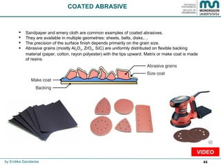
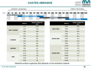
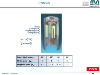
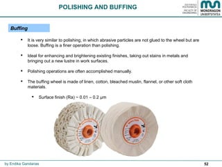
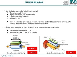
The document discusses various abrasive technologies used for finishing surfaces, including grinding, honing, polishing, lapping, and others. It covers the principles, processes, equipment, and applications for each technology. Key abrasive processes covered include grinding (flat, cylindrical, centerless), honing, polishing, lapping, and emerging techniques like abrasive flow machining and chemical mechanical polishing. The document provides an overview of abrasive machining as an important finishing technique.
Producing hole is one of the most common machining operation on a machining center.
Machining center have many hole making cycles such as Spot Drilling, Reaming, Deep Hole drilling, Peck drilling etc.
in this Ppt all canned cycle are explained i;e G70 G71 G72 G73 G75 G76 G81
Modern precision manufacturing demands extreme dimensional accuracy and surface finish.Such performance is very difficult to achieve manually, if not impossible, even with expert operators. In cases where it is possible, it takes much higher time due to the need for frequent dimensional measurement to prevent overcutting. It is thus obvious that automated motion control would replace manual “handwheel” control in modern manufacturing. Development of computer numerically controlled (CNC) machines has also made possible the automation of the machining processes with flexibility to handle production of small to medium batch of parts. In the 1940s when the U.S. Air Force perceived the need to manufacture complex parts for highspeed aircraft. This led to the development of computer-based automatic machine tool controls also known as the Numerical Control (NC) systems. Commercial production of NC machine tools started around the fifties and sixties around the world. Note that at this time the microprocessor has not yet been invented. Initially, the CNC technology was applied on lathes, milling machines, etc. which could perform a single type of metal cutting operation. Later, attempt was made to handle a variety of workpieces that may require several different types machining operations and to finish them in a single set-up. Thus CNC machining Centres capable of performing multiple operations were developed. To start with, CNC machining centres were developed for machining prismatic components combining operations like milling, drilling, boring and tapping. Gradually machines for manufacturing cylindrical components, called turning centers were developed.
Automatically controlling a machine tool based on a set of pre-programmed machining and movement instructions is known as numerical control, or NC.In a typical NC system the motion and machining instructions and the related numerical data, together called a part program, used to be written on a punched tape. The part program is arranged in the form of blocks of information, each related to a particular operation in a sequence
of operations needed for producing a mechanical component. The punched tape used to be read one block at a time. Each block contained, in a particular syntax, information needed for processing a particular machining instruction such as, the segment length, its cutting speed, feed, etc. These pieces of information were related to the final dimensions of the workpiece (length, width, and radii of circles) and the contour forms (linear, circular, or other) as per the drawing. Based on these dimensions, motion commands were given separately for each axis of motion. Other instructions and related machining parameters, such as cutting speed, feed rate, as well as auxiliary functions related to coolant flow, spindle speed, part clamping, are also provided in part programs depending on manufacturing specifications such as tolerance and surface finish. Punched tapes are mostly obsolete.
education is a key for everything so the objective of this slide is to share knowledge to the glob in my area of specialization.
This lecture note is basically designed for mechanical Engineering Manufacturing stream students and Instructors.
INTRODUCTION: The Turbo-Finish process (also referred to as Turbo-Abrasive Machining )imparts beneficial compressive residual stress to edges and surfaces. and as all critical features of the part are processed simultaneously, it can produce a stress equilibrium throughout the entire part. One of the signature advantages of the process is that it is capable of producing peening like metal surface improvement effects, while simultaneously developing isotropic surfaces and deburring and edge-contouring sharp edged features This combination of edge and surface effects can help extend part life on components by mitigating crack propagation.
A4 Information Brochure for Australian EnviroblastMark Angus
A4 information brochure for print and online marketing for Australian Enviroblast in Adelaide. Copywriting and editorial design by Mark Angus for Cadogan and Hall.
We supply all types of abrasive media for shot blasting machines. For more details, please visit us at www.synco.co.in or email us at trideep@synco.co.in
Trideep Raj Bhandari
Synco Industries Limited
Finishing and polishing of cast metal framework/prosthodontic coursesIndian dental academy
The Indian Dental Academy is the Leader in continuing dental education , training dentists in all aspects of dentistry and
offering a wide range of dental certified courses in different formats.for more details please visit
www.indiandentalacademy.com
Learn about methods to more quickly and economically machine materials such as high nickel-based super alloys or intermetallics such as gamma titanium aluminide. Philip Varghese, group leader of Saint-Gobain’s Advanced Application Engineering, showcases emerging trends in grinding of materials, with focus on turbine engine aerospace components. Originally presented at IMTS 2016.
As rail track technology continues to make major advances, the requirement for abrasives in maintenance and repair operations is increasing. As a multi-solution provider, Saint-Gobain offers a number of abrasive products which comply with all European health, safety and environmental standards and are specially designed for cutting and grinding rail track and surrounding materials.
Norton lanserar en serie nya kapskivor speciellt avsedda för användning inom gjuterier. De nya kapskivorna är baserade på ett helt nytt bindemedelssystem, FoundryX, som uppges ha flera fördelar som snabbare och effektivare kapning.
Saint-Gobain Abrasives, under the Norton brand, has introduced in the market a new range of cut-off wheels for use in Foundry environments. This latest generation of cut-off products has been developed with the new Foundry X bond technology, engineered to increase cut rate and wheel life in all foundry cut-off applications.
Nortonin uudet FoundryX –katkaisulaikat valimoille takaavat paremman aineenpoiston ja niiden käyttöikä on pidempi. Katkaisulaikoilla, joissa on Norzon-hioma-ainetta, aineenpoisto voi tehostua 50%. FoundryX:ää käytetetään katkaistaessa valurautaa, ruostumatonta sekä runsas- ja matalaseosteista terästä.
Norton Paradigm is an innovative porous metal bond platform featuring an exclusive chemistry delivering an entirely new grain adhesion science, resulting in improved product versatility across a wide range of precision grinding applications.
Norton lanserar ett nytt metallbindemedel för diamantslipskivor. Det nya bindemedlet, som har beteckningen Paradigm, har hög porositet och bättre fasthållning av slipkornen vilket ger kostnadseffektiviseringar vid precisionsslipning av hårdmetall.
Norton lanseeraa uuden metallisen sideaineen timattihiomalaikoille. Uusi Paradigm-sideaine on erittäin huokoinen ja siinä on parempi hiomajyvän kiinnitys, minkä ansiosta kovametallin hionnassa saavutetaan kustannussäästöjä.
Saint-Gobain Abrasives, under its Norton brand has launched a new range of high performance wheels for cutting-off and grinding primarily for use in oil & gas, off-shore, energy, transportation, foundry, shipyard and metal fabrication markets. The new range, Norton Quantum, gives faster and more aggressive cutting and grinding.
Manufacturing Technologies bibliography.for presentations.
Fabrikazio Teknologien aurkezpenetan erabilitako bibliografia.
Bibliografía empleada en las presentaciones de Tecnologías de Fabricación.
Manufacturing Technologies bibliography.for presentations.
Fabrikazio Teknologien aurkezpenetan erabilitako bibliografia.
Bibliografía empleada en las presentaciones de Tecnologías de Fabricación.
Microtechnologies: past, present and futureendika55
Microtechnologies description: past, present and future
Mikroteknologien deskribapena: lehena, oraina eta geroa
Descripción de las microtecnologías: pasado, presente y futuro
Microtechnologies: Past, present and futureendika55
Microtechnologies description: past, present and future
Mikroteknologien deskribapena: lehena, oraina eta geroa
Descripción de las Microtecnologías: pasado, presente y futuro
Explore the innovative world of trenchless pipe repair with our comprehensive guide, "The Benefits and Techniques of Trenchless Pipe Repair." This document delves into the modern methods of repairing underground pipes without the need for extensive excavation, highlighting the numerous advantages and the latest techniques used in the industry.
Learn about the cost savings, reduced environmental impact, and minimal disruption associated with trenchless technology. Discover detailed explanations of popular techniques such as pipe bursting, cured-in-place pipe (CIPP) lining, and directional drilling. Understand how these methods can be applied to various types of infrastructure, from residential plumbing to large-scale municipal systems.
Ideal for homeowners, contractors, engineers, and anyone interested in modern plumbing solutions, this guide provides valuable insights into why trenchless pipe repair is becoming the preferred choice for pipe rehabilitation. Stay informed about the latest advancements and best practices in the field.
Student information management system project report ii.pdfKamal Acharya
Our project explains about the student management. This project mainly explains the various actions related to student details. This project shows some ease in adding, editing and deleting the student details. It also provides a less time consuming process for viewing, adding, editing and deleting the marks of the students.
About
Indigenized remote control interface card suitable for MAFI system CCR equipment. Compatible for IDM8000 CCR. Backplane mounted serial and TCP/Ethernet communication module for CCR remote access. IDM 8000 CCR remote control on serial and TCP protocol.
• Remote control: Parallel or serial interface.
• Compatible with MAFI CCR system.
• Compatible with IDM8000 CCR.
• Compatible with Backplane mount serial communication.
• Compatible with commercial and Defence aviation CCR system.
• Remote control system for accessing CCR and allied system over serial or TCP.
• Indigenized local Support/presence in India.
• Easy in configuration using DIP switches.
Technical Specifications
Indigenized remote control interface card suitable for MAFI system CCR equipment. Compatible for IDM8000 CCR. Backplane mounted serial and TCP/Ethernet communication module for CCR remote access. IDM 8000 CCR remote control on serial and TCP protocol.
Key Features
Indigenized remote control interface card suitable for MAFI system CCR equipment. Compatible for IDM8000 CCR. Backplane mounted serial and TCP/Ethernet communication module for CCR remote access. IDM 8000 CCR remote control on serial and TCP protocol.
• Remote control: Parallel or serial interface
• Compatible with MAFI CCR system
• Copatiable with IDM8000 CCR
• Compatible with Backplane mount serial communication.
• Compatible with commercial and Defence aviation CCR system.
• Remote control system for accessing CCR and allied system over serial or TCP.
• Indigenized local Support/presence in India.
Application
• Remote control: Parallel or serial interface.
• Compatible with MAFI CCR system.
• Compatible with IDM8000 CCR.
• Compatible with Backplane mount serial communication.
• Compatible with commercial and Defence aviation CCR system.
• Remote control system for accessing CCR and allied system over serial or TCP.
• Indigenized local Support/presence in India.
• Easy in configuration using DIP switches.
NO1 Uk best vashikaran specialist in delhi vashikaran baba near me online vas...Amil Baba Dawood bangali
Contact with Dawood Bhai Just call on +92322-6382012 and we'll help you. We'll solve all your problems within 12 to 24 hours and with 101% guarantee and with astrology systematic. If you want to take any personal or professional advice then also you can call us on +92322-6382012 , ONLINE LOVE PROBLEM & Other all types of Daily Life Problem's.Then CALL or WHATSAPP us on +92322-6382012 and Get all these problems solutions here by Amil Baba DAWOOD BANGALI
#vashikaranspecialist #astrologer #palmistry #amliyaat #taweez #manpasandshadi #horoscope #spiritual #lovelife #lovespell #marriagespell#aamilbabainpakistan #amilbabainkarachi #powerfullblackmagicspell #kalajadumantarspecialist #realamilbaba #AmilbabainPakistan #astrologerincanada #astrologerindubai #lovespellsmaster #kalajaduspecialist #lovespellsthatwork #aamilbabainlahore#blackmagicformarriage #aamilbaba #kalajadu #kalailam #taweez #wazifaexpert #jadumantar #vashikaranspecialist #astrologer #palmistry #amliyaat #taweez #manpasandshadi #horoscope #spiritual #lovelife #lovespell #marriagespell#aamilbabainpakistan #amilbabainkarachi #powerfullblackmagicspell #kalajadumantarspecialist #realamilbaba #AmilbabainPakistan #astrologerincanada #astrologerindubai #lovespellsmaster #kalajaduspecialist #lovespellsthatwork #aamilbabainlahore #blackmagicforlove #blackmagicformarriage #aamilbaba #kalajadu #kalailam #taweez #wazifaexpert #jadumantar #vashikaranspecialist #astrologer #palmistry #amliyaat #taweez #manpasandshadi #horoscope #spiritual #lovelife #lovespell #marriagespell#aamilbabainpakistan #amilbabainkarachi #powerfullblackmagicspell #kalajadumantarspecialist #realamilbaba #AmilbabainPakistan #astrologerincanada #astrologerindubai #lovespellsmaster #kalajaduspecialist #lovespellsthatwork #aamilbabainlahore #Amilbabainuk #amilbabainspain #amilbabaindubai #Amilbabainnorway #amilbabainkrachi #amilbabainlahore #amilbabaingujranwalan #amilbabainislamabad
Industrial Training at Shahjalal Fertilizer Company Limited (SFCL)MdTanvirMahtab2
This presentation is about the working procedure of Shahjalal Fertilizer Company Limited (SFCL). A Govt. owned Company of Bangladesh Chemical Industries Corporation under Ministry of Industries.
Welcome to WIPAC Monthly the magazine brought to you by the LinkedIn Group Water Industry Process Automation & Control.
In this month's edition, along with this month's industry news to celebrate the 13 years since the group was created we have articles including
A case study of the used of Advanced Process Control at the Wastewater Treatment works at Lleida in Spain
A look back on an article on smart wastewater networks in order to see how the industry has measured up in the interim around the adoption of Digital Transformation in the Water Industry.
CFD Simulation of By-pass Flow in a HRSG module by R&R Consult.pptxR&R Consult
CFD analysis is incredibly effective at solving mysteries and improving the performance of complex systems!
Here's a great example: At a large natural gas-fired power plant, where they use waste heat to generate steam and energy, they were puzzled that their boiler wasn't producing as much steam as expected.
R&R and Tetra Engineering Group Inc. were asked to solve the issue with reduced steam production.
An inspection had shown that a significant amount of hot flue gas was bypassing the boiler tubes, where the heat was supposed to be transferred.
R&R Consult conducted a CFD analysis, which revealed that 6.3% of the flue gas was bypassing the boiler tubes without transferring heat. The analysis also showed that the flue gas was instead being directed along the sides of the boiler and between the modules that were supposed to capture the heat. This was the cause of the reduced performance.
Based on our results, Tetra Engineering installed covering plates to reduce the bypass flow. This improved the boiler's performance and increased electricity production.
It is always satisfying when we can help solve complex challenges like this. Do your systems also need a check-up or optimization? Give us a call!
Work done in cooperation with James Malloy and David Moelling from Tetra Engineering.
More examples of our work https://www.r-r-consult.dk/en/cases-en/
Hierarchical Digital Twin of a Naval Power SystemKerry Sado
A hierarchical digital twin of a Naval DC power system has been developed and experimentally verified. Similar to other state-of-the-art digital twins, this technology creates a digital replica of the physical system executed in real-time or faster, which can modify hardware controls. However, its advantage stems from distributing computational efforts by utilizing a hierarchical structure composed of lower-level digital twin blocks and a higher-level system digital twin. Each digital twin block is associated with a physical subsystem of the hardware and communicates with a singular system digital twin, which creates a system-level response. By extracting information from each level of the hierarchy, power system controls of the hardware were reconfigured autonomously. This hierarchical digital twin development offers several advantages over other digital twins, particularly in the field of naval power systems. The hierarchical structure allows for greater computational efficiency and scalability while the ability to autonomously reconfigure hardware controls offers increased flexibility and responsiveness. The hierarchical decomposition and models utilized were well aligned with the physical twin, as indicated by the maximum deviations between the developed digital twin hierarchy and the hardware.
1. BACHELOR OF ENGINEERINGBACHELOR OF ENGINEERING
MANUFACTURING TECHNOLOGIESMANUFACTURING TECHNOLOGIES
ABRASIVE TECHNOLOGIESABRASIVE TECHNOLOGIES
by Endika Gandarias
2. 2by Endika Gandarias
Dr. ENDIKA GANDARIAS MINTEGI
Mechanical and Manufacturing department
Mondragon Unibertsitatea - www.mondragon.edu
(Basque Country)
www.linkedin.com/in/endika-gandarias-mintegi-91174653
Further presentations: www.symbaloo.com/mix/manufacturingtechnology
3. 3
CONTENTS
BIBLIOGRAPHY
INTRODUCTION
GRINDING BENCH GRINDING
BENCH GRINDING BLASTING
BLASTING WIRE BRUSHING
WIRE BRUSHING GRINDING
MASS FINISHING MASS FINISHING
COATED ABRASIVE COATED ABRASIVE
HONING HONING
POLISHING AND BUFFING POLISHING AND BUFFING
LAPPING LAPPING
SUPERFINISHING SUPERFINISHING
OTHERS:
ABRASIVE FLOW MACHINING
ELECTRO-POLISHING
ELECTROLYTIC GRINDING
CHEMICAL MECHANICAL POLISHING
POLISHING USING MAGNETIC FIELDS
GLOSSARY
by Endika Gandarias
HIGH
LOW BETTER
WORSE
5. 5
The author would like to thank all the bibliographic references and videos that
have contributed to the elaboration of these presentations.
For bibliographic references, please refer to:
• http://www.slideshare.net/endika55/bibliography-71763364 (PDF file)
• http://www.slideshare.net/endika55/bibliography-71763366 (PPT file)
For videos, please refer to:
• www.symbaloo.com/mix/manufacturingtechnology
BIBLIOGRAPHY
by Endika Gandarias
7. 7
INTRODUCTION
• Usually brought into play after machining, casting, forging, sheet metal forming, etc.
• It can be used on all type of materials.
• A variety of abrasive machining processes and machinery is available.
• Abrasive machining is necessary and economical when:
• Hard materials
• Brittle materials
• Excellent surface finish and dimensional tolerances are required.
by Endika Gandarias
Rz: Maximum height of the
roughness profile
Ra: Arithmetical mean deviation
of the roughness profile
Rq: Root mean square deviation
of the roughness profile
Roughness 2D Parameters
9. 9
• All abrasive operations can be considered as material removal processes with geometrically
undefined cutting edges. Each abrasive grain acts like a single cutting tool with undefined
geometry but usually with high negative rake angle.
INTRODUCTION
by Endika Gandarias
10. 10
Sharping with
stones
Rotary stone
Pedal with shank
and connecting rod
CHARLES MOSELEY
Cylindrical grinding machine
SWEN PULSON Extra-strong
grinding wheel
BROWN & SHARPE Universal grinding
NORTON
Horizontal grinding tool holder
ACHESON
Carborundum (Silicon carbide)
CINCINNATI Centerless
grinding machine GENERAL ELECTRIC
Synthetic diamond
INTRODUCTION
by Endika Gandarias
13. 13
GRINDING
Introduction
It is an abrasive technology in which abrasive particles are contained in bonded grinding
wheel.
The feed (F) and depth of cut (ap) in grinding are small, while the cutting speed (Vc) is high.
Dimensional accuracy: 0,3 – 0,5 µm
Surface finish (Ra) ~ 0,1 – 1,6 µm
Specific cutting energy: 50 J/mm3
by Endika Gandarias
VIDEO
14. 14
Introduction
GRINDING
A grinding wheel consists of:
Hard abrasive grains called grits perform the cutting or material removal Hardness
Bonding material holds particles in place and gives the profile to the wheel Toughness
Conventional abrasive wheel materials:
• Aluminium oxide (Al2O3)
• Silicon carbide wheels (SiC)
Superabrasive wheels:
• Diamond
• CBN (Cubic Boron Nitride)
Conventional abrasive wheels Superabrasive wheels
by Endika Gandarias
15. 15
1 14192 250 X 25 X 25 51-A-36-L-5-V-23 40m/s
GEOMETRY DIMENSIONS COMPOSITION Max SPEED
PRODUCT
NUMBER
Grinding wheel specification
It is needed to be specified:
• Wheel diameter (D)
• Width and depth of rim (T)
• Bore diameter (H)
GRINDING
by Endika Gandarias
16. 16
Standard Marking System for Aluminum-Oxide and Silicon-Carbide Bonded Abrasives
GRINDING
Grinding wheel specification
by Endika Gandarias
17. 17
ABRASIVE TYPE:
Al2O3 (2000-3000) high tensile strength materials, ductile materials “corundum”
SiC (2100-3000) low tensile strength, brittle and non metallic materials
“carborundum”
CBN (4000-5000) very hard materials “borazon”
Diamond (7000-8000) carbide & very hard non ferrous materials
ABRASIVE GRAIN SIZE:
Coarse Soft & ductile materials or poor Ra = roughing
Fine Hard & brittle materials or excellent Ra = finishing
GRADE (abrasive grain-bonding joining strength):
Soft wheel hard materials machining (to have fresh abrasive) or poor Ra = roughing
Hard wheel soft materials machining or excellent Ra = finishing
STRUCTURE (porosity):
Open Soft & ductile materials
High removal rate or poor Ra = roughing
Dense Long wheel life & precise wheel forms/profiles or excellent Ra = finishing
BOND TYPE:
Vitrified: most common, brittle bond
Resinoid: more flexible bond
Rubber: very flexible bond
GRINDING
Grinding wheel specification
by Endika Gandarias
VIDEO
18. 18
Grinding wheel specification
GRINDING
by Endika Gandarias
The heavy point of the grinding
wheel is marked with an arrow.
Depending of the wheel
manufacturer, it needs to be
mounted with the arrow pointing
downwards or upwards.
VIDEO
19. 19
Truing is the process of making a grinding wheel round and concentric with the
grinding wheel spindle axis. Truing is also the process of forming a specific
shape on the face of the wheel.
Dressing is the process of conditioning the surface of a trued wheel to expose
the grain for efficient grinding action.
GRINDING
Truing and dressing a grinding wheel
After truing
After dressing
Truing and dressing can often be performed at the same time, even using
the same tool.
WHEEL OR GRINDING
DRESSERS
by Endika Gandarias
VIDEO
20. 20
GRINDING
• It is used to remove material from flat surfaces.
• Spindle position can be horizontal or vertical.
• Dimensional tolerance ~ IT5 – IT6
• Surface finish (Ra) ~ 0,15 – 0,6 µm
Grinding technology classification
Flat or surface grinding
by Endika Gandarias
VIDEO
21. 21
ALTERNATIVE
WORKTABLE
ALTERNATIVE
WORKTABLE
ROTATIVE
WORKTABLE
ROTATIVE
WORKTABLE
• Long and narrow surfaces.
• Worse efficiency than the frontal
grinding.
• Better finishing than the frontal grinding.
• High material start-up rate.
• Worse finishing than the tangential
grinding.
• Tools: rings, cups, segments
GRINDING
Flat or surface grinding
TANGENTIAL GRINDING WHEEL FRONTAL GRINDING WHEEL
VIDEO VIDEO
Grinding technology classification
by Endika Gandarias
VIDEO
22. 22
PropsGuide
Engine Cutting blade
GRINDING
Flat or surface grinding
APPLICATIONS
Gear
Other
Grinding technology classification
by Endika Gandarias
TANGENTIAL
FRONTAL FRONTAL
TANGENTIAL TANGENTIAL
VIDEO
23. 23
GRINDING
Creep feed grinding
It uses large depth of cuts (typically ap on the order of 1 - 6 mm) and low feed rates (F).
The wheel is often continuously dressed.
It is essential to use a high pressure coolant system and soft wheels with open structure to keep
temperature low.
Advantages: High material removal rates and productivity (the wheel is continuously cutting).
Grinding technology classification
Conventional grinding contrasted to creep feed grinding
by Endika Gandarias
25. 25
Cylindrical grinding
GRINDING
Grinding technology classification
• It is used to remove external or internal cylindrical surfaces.
• It is also known as Universal grinding.
• The workpiece is usually held in a rotating chuck in the headstock or between centers.
• The wheel rotates at very high rotational speed (N).
• Dimensional tolerance ~ IT6 – IT8
• Surface finish (Ra) ~ 0,8 – 1,6 µm
by Endika Gandarias
Feed
VIDEO
28. 28
Cylindrical grinding
GRINDING
Grinding technology classification
SPECIAL OPERATIONS
STEPPED SHAPE GRINDING WHEEL THREAD GRINDING
(a) traverse grinding (b) plunge grinding
by Endika Gandarias
VIDEO
GEAR GRINDING
VIDEO
29. 29
Cylindrical grinding
GRINDING
Grinding technology classification
SPECIAL OPERATIONS
The part rotation and the distance x between centers
is varied and synchronized to grind the particular
workpiece shape.
GRINDING A NON-CYLINDRICAL PART
VIDEO
by Endika Gandarias
VIDEO
32. 32
Centerless grinding
GRINDING
Grinding technology classification
• It is used for high length to diameter ratio parts.
• Workpiece is NOT supported by centers or chucks,
but by a blade or between rollers.
• Easy to be automatizated.
• Dimensional tolerance ~ IT4 – IT6
• Surface finish (Ra) ~ 0,4 – 0,8 µm
(a) Through-feed grinding (b) Plunge grinding
EXTERNAL GRINDING
OPERATIONS
VIDEOVIDEO
by Endika Gandarias
(a) Through-feed grinding
VIDEO
VIDEO
36. 36
The work is held (usually manually) against the flat surface of the wheel to accomplish the
grinding operation.
It can be a bench grinder or pedestal grinder.
Surface finish (Ra) ~ 0,2 - 1,6 µm
BENCH GRINDING
by Endika Gandarias
VIDEO
38. 38
This is the finishing method by spraying blasting abrasives from a nozzle with the force of
compressed air to workpieces.
It is used for:
Cleaning
Deburring
Descaling
Finishing
Peening (increases hardness and eliminates residual stresses)
Surface finish (Ra) ~ 1,5 µm
BLASTING
by Endika Gandarias
VIDEOVIDEO
40. 40
WIRE BRUSHING
It produces a fine and controlled surface texture.
Wire brushing is typically used for:
removal of rust or corrosion from metal objects.
rough-polishing castings, hot-rolled steel,…
Brushes can be made of nylon, steel or brass filaments, and may contain abrasives.
Surface finish (Ra) ~ 0,1 – 1,5 µm
by Endika Gandarias
VIDEOVIDEO
42. 42
MASS FINISHING
Mass finishing is a surface improving mass-production system. A mixture of parts, abrasive
media (vitrified, alumina, plastic, organic or metallic) and compounds (liquid or powder) are placed
into a container or barrel, and rotated at a predetermined speed.
It is used for:
Deburring
Radiusing
Smoothing
Descaling
Luster and mirror finishing.
There are several types of barrel motion:
Centrifugal barrel
Centrifugal disc
Vibratory bowl
Rotary tumbling
Surface finish (Ra) ~ 0,05 – 1,6 µm
HIGH
LOW
Centrifugal barrel Centrifugal disc
Vibratory bowl Barrel / Rotary tumbling
by Endika Gandarias
VIDEO
VIDEO VIDEO
VIDEO VIDEO
VIDEO
VIDEO
44. 44
COATED ABRASIVE
Sandpaper and emery cloth are common examples of coated abrasives.
They are available in multiple geometries: sheets, belts, disks,…
The precision of the surface finish depends primarily on the grain size.
Abrasive grains (mostly Al2O3, ZrO2, SiC) are uniformly distributed on flexible backing
material (paper, cotton, rayon polyester) with the tips upward. Matrix or make coat is made
of resins.
by Endika Gandarias
VIDEO
45. 45
COATED ABRASIVE
by Endika Gandarias
FEPA P
GRAIN DIAMETER
(µm)
VERY COARSE
P12 1815
P16 1324
P20 1000
P24 764
COARSE
P30 642
P36 538
P40 425
P50 336
MEDIUM
P60 269
P80 201
P100 162
FINE
P120 125
P150 100
P180 82
P220 68
FEPA P
GRAIN DIAMETER
(µm)
VERY FINE
P240 58.5
P280 52.2
P320 46.2
EXTRA FINE
P360 40.5
P400 35.0
P500 30.2
P600 25.8
P800 21.8
SUPER FINE
P1000 18.3
P1200 15.3
P1500 12.6
P2000 10.3
P2500 8.4
P3000 7
P5000 5
Obtained surface roughness (Ra) depends on the workpiece material.
46. 46
Coated abrasives are also used as belts for high material removal rate and good surface finish.
Typical applications: surgical implants, medical & dental instruments, golf clubs, firearms, turbine
blades.
Dimensional tolerance ~ IT10 – IT11
Surface finish ~ 0,4 – 0,8 µm
COATED ABRASIVE
Belt grinding
by Endika Gandarias
VIDEOVIDEO
48. 48
HONING
Honing is used to improve the surface finish and roundness of bored or ground holes.
It creates a characteristic cross-hatched surface that retains lubrication.
As it is a slow rotation operation, no heat affected zone (HAZ) appears.
Typical application: bores of internal combustion engines.
Dimensional tolerance ~ IT4 – IT5
Surface finish (Ra) ~ 0,05 – 0,2 µm (Al2O3 or SiC)
by Endika Gandarias
OscillationVa
Slow rotation
Vu
VIDEOVIDEO
51. 51
POLISHING AND BUFFING
Abrasive particles are glued to the outside periphery of the polishing wheel and it rotates
at high speeds.
Polishing is used to remove scratches and burrs.
Polishing operations are often accomplished manually.
The polishing wheel is made of fabrics, leather or felt.
Surface finish (Ra) ~ 0.02 – 0.4 μm
BEFOREAFTER
Polishing
by Endika Gandarias
VIDEOVIDEO
52. 52
It is very similar to polishing, in which abrasive particles are not glued to the wheel but are
loose. Buffing is a finer operation than polishing.
Ideal for enhancing and brightening existing finishes, taking out stains in metals and
bringing out a new lustre in work surfaces.
Polishing operations are often accomplished manually.
The buffing wheel is made of linen, cotton, bleached muslin, flannel, or other soft cloth
materials.
Surface finish (Ra) ~ 0.01 – 0.2 μm
Buffing
POLISHING AND BUFFING
by Endika Gandarias
54. 54
LAPPING
(b) lapping on cylindrical surfaces(a) lapping on flat surfaces
It is a low speed, low ablading process.
Lapping uses fluid suspension of very small abrasive particles between
workpiece and lap. Lap usually made of cast iron, copper, leather, or
cloth.
Typical application: optical lenses, metallic bearing surfaces, gages.
Dimensional tolerance ~ IT4 – IT5
Surface finish (Ra) ~ 0.025 – 0.1 μm
by Endika Gandarias
VIDEO VIDEO
56. 56
SUPERFINISHING
It is similar to honing (also called “microhoning”):
Shorter strokes (<5 mm)
Higher frequencies (>400 cycles/min)
Lower pressures (10-40 psi)
Smaller grit size
Copious amount of low viscosity lubricant-coolant is used and it establishes a continuous film
between the stone and the workpiece and separates them.
Stroke paths controlled so that a single grit never traverses the same path twice.
Dimensional tolerance ~ IT3 – IT4
Surface finish (Ra) ~ 0.01 – 0.04 μm
(a) cylindrical microhoning (b) centerless microhoning
by Endika Gandarias
VIDEOVIDEO
VIDEO
58. 58
OTHERS
A putty of abrasive grains (SiC or diamond) is forced back and forth through the workpiece.
It is particularly suitabe for workpieces with internal cavities.
It is used for:
Deburring
Radiusing
Polishing
Dimensional tolerance ~ ± 0,005mm
Surface finish (Ra) ~ 0,05 – 0,4 µm
Abrasive Flow Machining
by Endika Gandarias
VIDEO
59. 59
This polishing method melts the surface of a workpiece by applying an electrolytic solution and
an electric DC current to workpiece.
Mirrorlike finishes can be obtained on metal surfaces. It is very suitable for irregular
geometries.
This process is also used for deburring operations.
Typical application: medical instrumentation, bone screws, stainless steel surfaces.
Surface finish (Ra) ~ 0.1 – 0.8 μm
OTHERS
Electropolishing
by Endika Gandarias
VIDEOVIDEO
60. 60
It is a variant of ElectroChemical Machining (ECM), and it is also known as electrochemical
grinding.
It is a process that combines electrochemical energy with mechanical energy to remove
material by grinding with a negatively charged abrasive grinding wheel, an electrolyte fluid, and
a positively charged workpiece.
Typically 90% of the metal is removed by electrolysis and 10% from the abrasive grinding
wheel (the wheel lasts a longer time). Thus, difficult materials independent of their hardness or
strength can be machined.
The wheel and workpiece must be electrically conductive.
OTHERS
Electrolytic grinding (ECG)
by Endika Gandarias
VIDEO
61. 61
OTHERS
Chemical Mechanical Polishing/Planarization is a process of smoothing surfaces.
It is a combination of mechanical free abrasive polishing and chemical etching (increases
material removal rate).
It may contain 1 or more workpiece carriers.
Typical applications: silicon wafers and integrated circuits.
Surface finish (Ra) ~ 0.035 – 0.0005 μm
Chemical Mechanical Polishing (CMP)
by Endika Gandarias
VIDEOVIDEO
62. 62
OTHERS
A magnetic field is used to force a homogeneous mixture of magnetic particles and abrasive
particles against the target surface.
The particles can be introduced into areas which are hard to reach by conventional techniques.
Typical applications: medical components, fluid systems, optics, dies and molds, electronic
components, microelectromechanical systems, and mechanical components.
Surface finish (Ra) ~ 200 – 0.001 μm
(a) magnetic float polishing of ceramice balls (b) magnetic field assisted polishing of rollers
Polishing Using Magnetic Fields
by Endika Gandarias
VIDEOVIDEO
64. 64
GLOSSARY
by Endika Gandarias
ENGLISH SPANISH BASQUE
Ablading Abrasión Urratze
Abrasive Abrasivo Urratzaile
Accuracy Precisión Doitasun
Attrition Erosión Erosio
Axial cutting depth Profundidad de pasada axial Sakontze sakonera
Axle Eje Ardatz
Backing Sustrato / Apoyo Substratu
Barrel Barril / Tonel Upel / Barrika
Barrel finishing Tambor de pulido Leunketa danbor
Batch Lote Sorta
Bearing Rodamiento Errodamendu
Bed Base Oinarri
Belt Cinta / Banda Banda
Belt grinding Lijado con cinta/banda Banda bidezko lixatze
Bench grinding Esmerilado Esmerilaketa
Between centers Entre centros Zentru artean
Binder Aglutinante Aglutinatzaile
Blade Cuchilla Hortz
Blasting Chorreado Jariaketa
Bleached muslin Muselina blanqueada Muselina zuritua
Bond Enlace Lotura
Bone Hueso Hezur
Brittle Frágil Hauskor
Buffing Abrillantado Distiraketa
Burr Rebaba Bizar
Camshaft Arbol de levas Espeka ardatza
Carborundum Carborundo Karborundum
Carriage Carro Orga
65. 65
GLOSSARY
by Endika Gandarias
ENGLISH SPANISH BASQUE
Carrier Transportador / Portador Garraiatzaile
Casting Fundición Galdaketa
Centerless grinding Rectificado sin centros Zentrugabeko artezketa
Chip Viruta Txirbil
Chuck Amarre / Porta Amarratze / Porta
Coarse Basto Baldar
Coated abrasive Papel / telas abrasivas Paper / Oihal urratzaileak
Compound Mezcla / Compuesto Nahaste
Corundum Corindón Korindoi
Cotton Algodón Kotoi
Crankshaft Cigüeñal Birabarki
Creep feed grinding Rectificado de profundidad Sakonerako artezketa
Cross-hatched Estrías cruzadas Ildaska gurutzatuak
Cup Copa Kopa
Cutting speed Velocidad de corte Ebaketa abiadura
Descaling Descascarillar / Desescamar / Desincrustar / Decapar
Azala kendu / Ezkata kendu / Inkrustazioak
kendu / Ugerra kendu
Dressing Reavivado Berpizketa
Drive spindle Cabezal motriz Buru eragilea
Emery Esmeril Esmeril
Emery cloth Paño de lija Lixa oihal
Engine Motor Motore
Fabric Tela Ohial
Face plate Plato plano Plater laua
Feed rate Avance por minuto Aitzinamendua minutuko
Felt Fieltro Feltro
Field Campo Eremu
Firearms Armas de fuego Su arma