Downloaded 420 times


![9
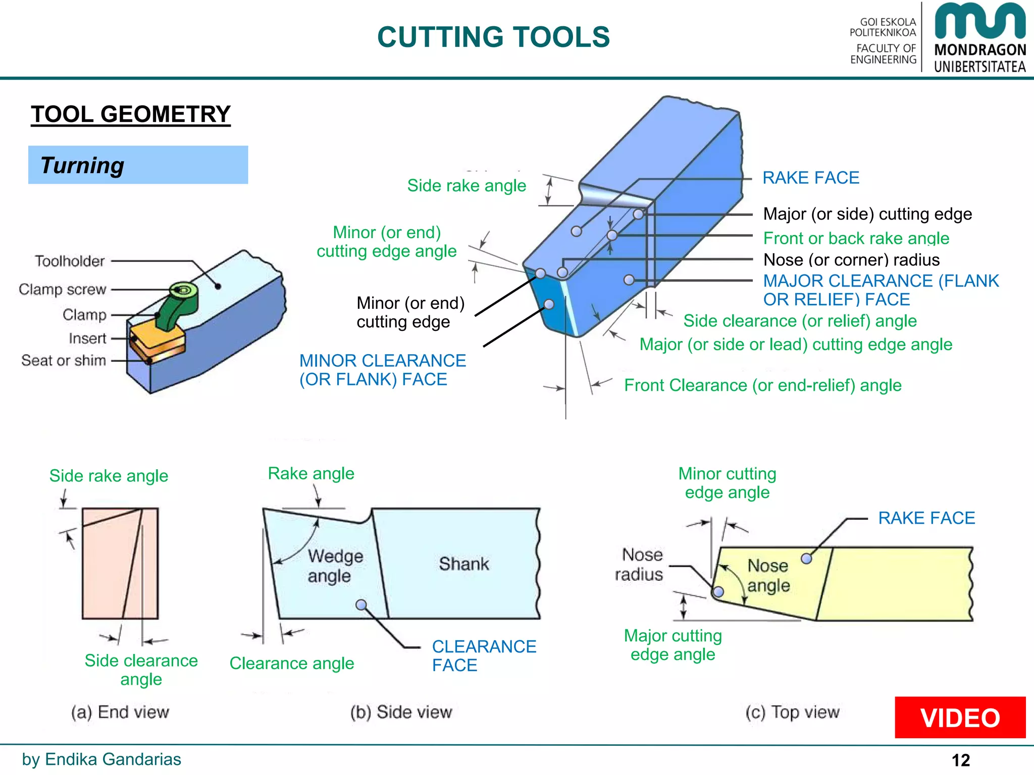
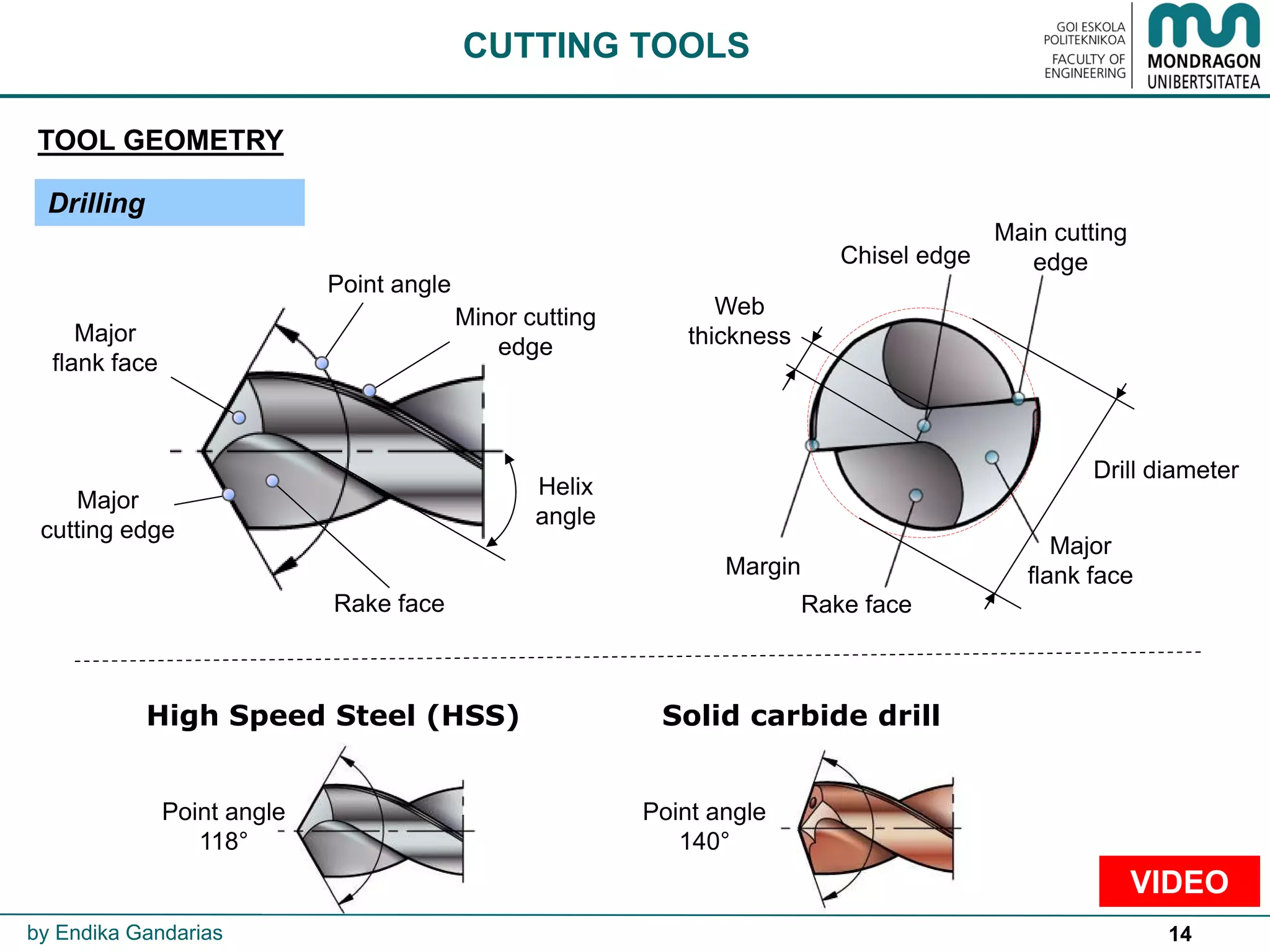
CUTTING TOOLS
by Endika Gandarias
Temperature [ºC]
Hardness[HRC]
1550
1400
1300
900
800
Ceramic
CBN
Carbide
(Hard metal)
Diamond
HSS
ºC](https://image.slidesharecdn.com/5cuttingconditions-170204214000/75/Cutting-conditions-9-2048.jpg)
![10
Feed [mm/rev]
Cuttingspeed[m/min]
50
CUTTING TOOLS
by Endika Gandarias](https://image.slidesharecdn.com/5cuttingconditions-170204214000/75/Cutting-conditions-10-2048.jpg)


![33
F [mm/min]
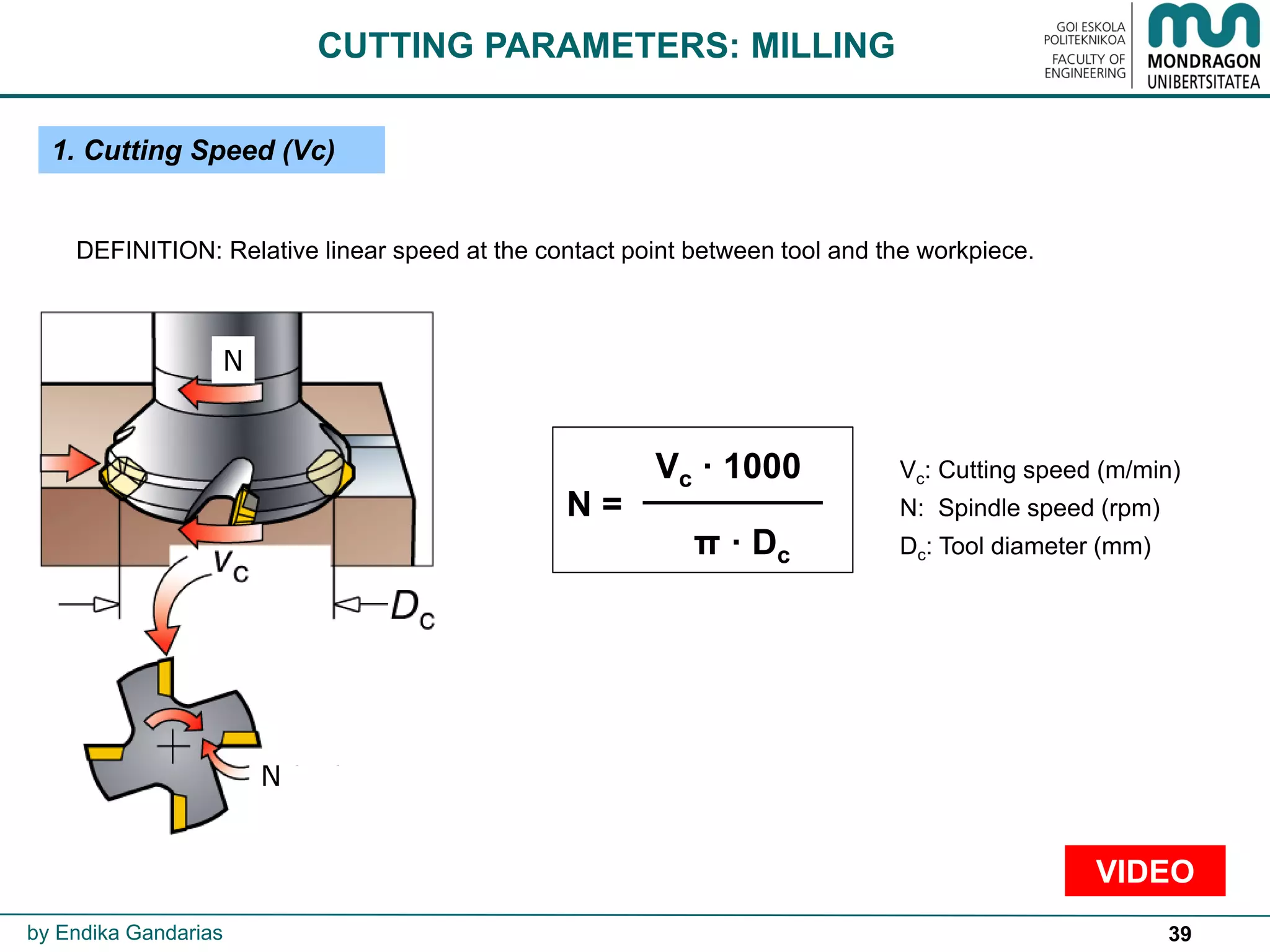
DEFINITION: Relative movement between the workpiece and the tool.
fn [mm/rev]
IN
TURNING
FEED PER
REVOLUTION
(fn)
→
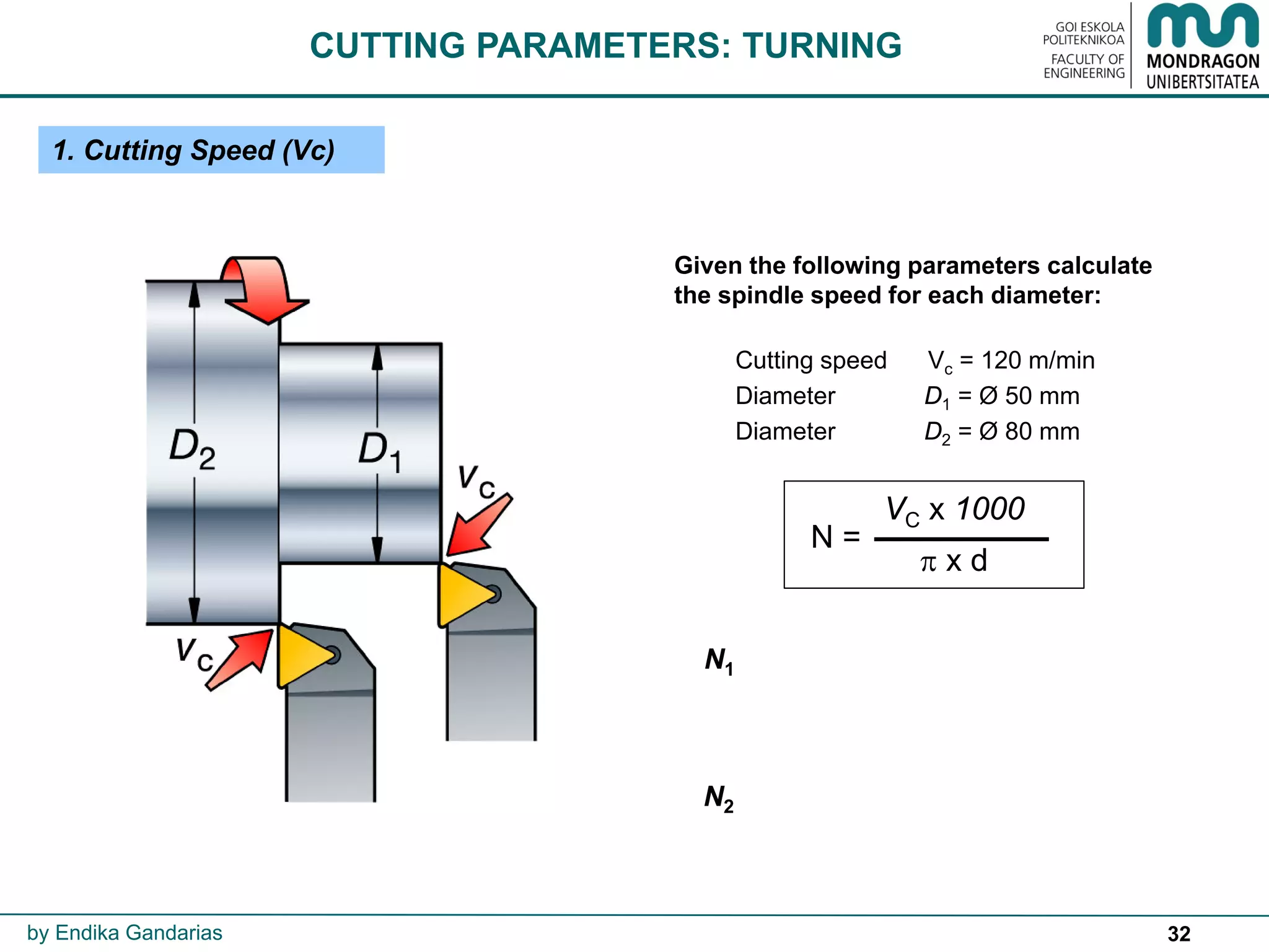
2. Feed
3. Cutting depth (ap)
FEED PER REVOLUTION
F = fn·N
CUTTING PARAMETERS: TURNING
FEED RATE
or
FEED PER MINUTE
by Endika Gandarias
F
ap
ap
ap](https://image.slidesharecdn.com/5cuttingconditions-170204214000/75/Cutting-conditions-33-2048.jpg)


![58
2. Feed
DEFINITION: Relative movement between the workpiece and the tool.
IN
DRILLING
FEED PER
REVOLUTION
(fn)
→
3. Cutting depth (ap)
F [mm/min]
FEED RATE
or
FEED PER MINUTE F = fn·N
CUTTING PARAMETERS: DRILLING
by Endika Gandarias
ap
VIDEO](https://image.slidesharecdn.com/5cuttingconditions-170204214000/75/Cutting-conditions-58-2048.jpg)


![80
SELECTION OF CUTTING CONDITIONS
3. GEOMETRY: Part geometry will define:
Dimensional tolerances, expected surface roughness values and geometrical
tolerances to be obtained.
Process limitations such as vibration, chatter,…
Tool geometry will be chosen according to the process operations to be accomplished.
4. MATERIAL: Tool-workpiece material combination is very important.
According to that, tool manufacturers usually offer customers cutting condition tables for
free. These tables are the result of many experiments carried out.
Usually these values correspond to a tool life of 15 minutes and should be regarded as
starting values. They are obtained according to Taylor’s equation.
Taylor’s Tool life formula: Vc * Tn = C
Expanded Taylor`s Tool life formula: Vc * Tn * fn
a * ap
b = C
Vc : Cutting speed [m/min]
fn : Feed per revolution [mm/rev]
ap : Cutting depth [mm]
T : Tool life [min]
a, b, n, C: Constants
by Endika Gandarias
VIDEO](https://image.slidesharecdn.com/5cuttingconditions-170204214000/75/Cutting-conditions-80-2048.jpg)


The document, authored by Endika Gandarias, explores comprehensive aspects of cutting tools and parameters essential for manufacturing technologies. It covers the selection of cutting conditions, tool geometries, and the effects of various cutting parameters on machining processes, emphasizing the importance of factors like cutting speed, feed rates, and machining time. Additionally, it discusses high-speed machining techniques and considerations in tool insert fabrication and performance.


