Downloaded 245 times


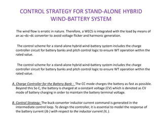
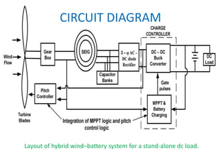
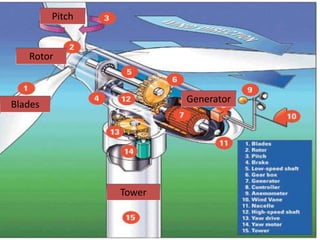
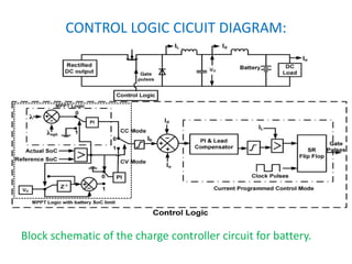
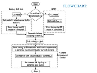
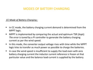
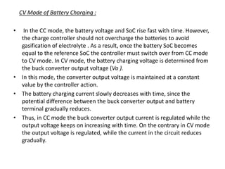
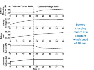
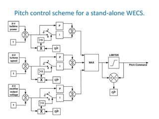
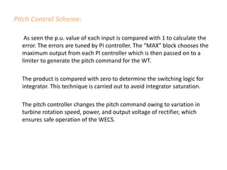
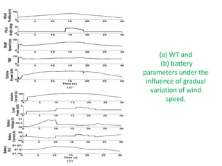
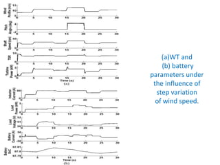
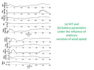


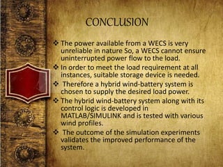
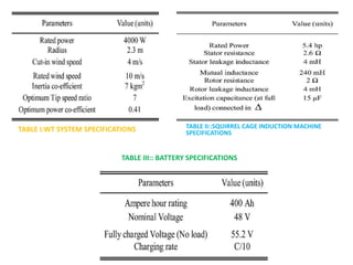


The document describes a control scheme for a stand-alone hybrid wind-battery energy system. The system includes a 4 kW wind turbine connected to a 5.4 hp squirrel cage induction generator. A 400 Ah lead-acid battery bank provides backup power storage. The control scheme uses maximum power point tracking (MPPT) to charge the batteries from the wind turbine. A pitch controller varies the blade pitch to regulate the turbine speed and electrical parameters. The batteries charge in constant current (CC) mode until fully charged, then switch to constant voltage (CV) mode to maintain the battery voltage without overcharging. Simulation results show the system can successfully regulate parameters and supply uninterrupted power under various wind speed conditions.