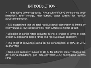
IMPROVED REACTIVE POWER CAPABILITY WITH GRID
CONNECTED DOUBLU FED INDUCTION GENERATOR
CONTENT
 INTRODUCTION
DOUBLY FED INDUCTION GENERATOR
OPERATION
REACTIVE CHARACTERISTICS OF DFIG
MODELLING OF DFIG
CAPABILITY CURVE OF DFIG
CONCLUSION
REFERENCE
INTRODUCTION
 The reactive power capability (RPC) curve of DFIG considering three
limitations( rotor voltage, rotor current, stator current) for reactive
power/consumption.
 It is established that the total reactive power generation is limited by
rotor voltage at low speeds and by rotor currents at higher speed.
Selection of partial rated converter rating is crucial in terms of cost,
efficiency, operating speed range and reactive power capability.
The effect of converters rating on the enhancement of RPC of DFIG
IS analyzed.
 Complete capability curves of DFIG for different stator voltages are
developing considering grid side converter(GSC) contribution towards
RPC
DOUBlY FED INDUCTION GENERATOR
DFIG equipped with self-commutated insulated gate bipolar transistor
(IGBT) voltage source converter (VSC) is one of the most popular
topologies used in wind power systems.
The reactive power capability is subject to several limitations which
change with the operating point.
Around synchronous operating point, a special attention is needed
since the limitation of maximum junction temperature of the IGBTs
cause a reduction on maximum permissible output current at the rotor
side.
Simulation results show that appropriate selection of PWM type is
necessary at around synchronous speed to increase the maximum
permissible rotor current as well as reactive power capability.
OPERATION OF DFIG
The DFIG consists of a 3 phase wound rotor and a 3 phase wound stator.
As the rotor rotates the magnetic field produced due to the ac current also
rotates at a speed proportional to the frequency of the ac signal applied to
the rotor windings.
The speed of rotation of the stator magnetic field depends on the rotor
speed as well as the frequency of the ac current fed to the rotor windings.
The whole system consists of two back to back converters – a machine side
converter is used to control the active and reactive powers by controlling
the d-q components of the rotor ,torque and speed of the machine.
Grid side converter is used to maintain a constant dc link voltage and
ensures the unity power factor operation
REACTIVE CHARACTERISTICS DFIG
It facilitates flow of active power from generation sources
to load centers and maintains bus voltages within
prescribed limits.
Stable operation of power systems requires the availability
of sufficient reactive generation.
The presence of power electronics control in DFIG makes
them a fast acting dynamic reactive resource as
compared to direct grid connected synchronous
generators.
Reactive power capability for a wind plant is a significant
additional cost compared to conventional units which
possess inherent reactive capability.
MODELLING OF DFIG
 The doubly fed induction generator has been used for years for
variable speed drives.
 Using vector control techniques, the bidirectional converter
assures energy generation at nominal grid frequency and nominal
grid voltage independently of the rotor speed.
 To compensate for the difference between the speed of the rotor
and the synchronous speed with the slip control
The main characteristics may be summarized as follows:
Limited operating speed range (-30% to + 20%)
Small scale power electronic converter (reduced power losses and
price)
Complete control of active power and reactive power exchanged
with the grid
Need for slip-rings
Need for gearbox (normally a three-stage one)
For a DFIG associated with a back-to-back converter on the rotor
side and with the stator directly connected to the grid
 An SFOC (stator flux oriented control) system is used in order to
control separately the active and reactive power on the stator side
CAPABILITYCURVE OF DFIG
The power output of a generator is usually limited to value within the
MVA rating by the capability of its prime mover.
When real power and terminal voltage is fixed, its armature and field
winding heating limits restricts the reactive power generation from the
generator.
The armature heating limit is a circle with radius, centered on the origin
 From the figure that at 100% plant output, the use of the capability
curve does not give much additional reactive support compared to the
0.95 leading operation.
Wind parks will very seldom operate continuously at 100% output in
the periods of operation below 100%, there is significant additional
reactive power available that could aid in improved system
performance.
CONCLUSION
The operation of DFIG wind farm implementing a
capability curve paves the way for regulatory changes.
In general guidelines for interconnecting wind farm are
used a restricted power factor.
 When DFIG work with capability curve, fully utilizing the
potential of DFIG wind farm may be obtain at no extra
cost to the wind farm owner.
 As the levels of wind penetration continues to increase
the reactive power the certain point it should be in limit.
 At the 100% penetration the limit of reactive power in
both CC and RPF are almost same.
REFERENCE
S.Chandrasekaran, C.Rossi, D.Casadei, A.Tani, “Improved Control
Strategy of Wind Turbine with DFIG for Low Voltage Ride Through Capability”
International Symposium on Power Electronics, Electrical Drives, Automation
and Motion, 2012, Sorrento, Italy.
Jiabing Hu, Hailiang Xu, Yikang He: “Coordinated Control of DFIG’s RSC
and GSC Under Generalized Unbalanced and Distorted Grid Voltage
Conditions”, IEEE transactions on industrial electronics, vol. 60, no. 7,
July 2013.
T. Sun, Z. Chen, and Frede Blaabjerg, “Voltage Recovery of Grid-
Connected Wind Turbines with DFIG After a Short-circuit Fault,” 2004 35th
Annual lEEE Power Electronics Specialists Conference.
J. I. Jang, Y. S. Kim, and D. C. Lee, "Active and reactive power control of
DFIG for wind energy conversion under unbalanced grid voltage," IPEMC
Shanghai, vol. 3, pp. 1487-1491, Aug. 2006.
THANK YOU

Improved reactive power capability with grid connected doubly fed induction generator

  • 1.
    IMPROVED REACTIVE POWERCAPABILITY WITH GRID CONNECTED DOUBLU FED INDUCTION GENERATOR
  • 2.
    CONTENT  INTRODUCTION DOUBLY FEDINDUCTION GENERATOR OPERATION REACTIVE CHARACTERISTICS OF DFIG MODELLING OF DFIG CAPABILITY CURVE OF DFIG CONCLUSION REFERENCE
  • 3.
    INTRODUCTION  The reactivepower capability (RPC) curve of DFIG considering three limitations( rotor voltage, rotor current, stator current) for reactive power/consumption.  It is established that the total reactive power generation is limited by rotor voltage at low speeds and by rotor currents at higher speed. Selection of partial rated converter rating is crucial in terms of cost, efficiency, operating speed range and reactive power capability. The effect of converters rating on the enhancement of RPC of DFIG IS analyzed.  Complete capability curves of DFIG for different stator voltages are developing considering grid side converter(GSC) contribution towards RPC
  • 4.
    DOUBlY FED INDUCTIONGENERATOR DFIG equipped with self-commutated insulated gate bipolar transistor (IGBT) voltage source converter (VSC) is one of the most popular topologies used in wind power systems. The reactive power capability is subject to several limitations which change with the operating point. Around synchronous operating point, a special attention is needed since the limitation of maximum junction temperature of the IGBTs cause a reduction on maximum permissible output current at the rotor side. Simulation results show that appropriate selection of PWM type is necessary at around synchronous speed to increase the maximum permissible rotor current as well as reactive power capability.
  • 5.
  • 6.
    The DFIG consistsof a 3 phase wound rotor and a 3 phase wound stator. As the rotor rotates the magnetic field produced due to the ac current also rotates at a speed proportional to the frequency of the ac signal applied to the rotor windings. The speed of rotation of the stator magnetic field depends on the rotor speed as well as the frequency of the ac current fed to the rotor windings. The whole system consists of two back to back converters – a machine side converter is used to control the active and reactive powers by controlling the d-q components of the rotor ,torque and speed of the machine. Grid side converter is used to maintain a constant dc link voltage and ensures the unity power factor operation
  • 7.
    REACTIVE CHARACTERISTICS DFIG Itfacilitates flow of active power from generation sources to load centers and maintains bus voltages within prescribed limits. Stable operation of power systems requires the availability of sufficient reactive generation. The presence of power electronics control in DFIG makes them a fast acting dynamic reactive resource as compared to direct grid connected synchronous generators. Reactive power capability for a wind plant is a significant additional cost compared to conventional units which possess inherent reactive capability.
  • 8.
    MODELLING OF DFIG The doubly fed induction generator has been used for years for variable speed drives.  Using vector control techniques, the bidirectional converter assures energy generation at nominal grid frequency and nominal grid voltage independently of the rotor speed.  To compensate for the difference between the speed of the rotor and the synchronous speed with the slip control The main characteristics may be summarized as follows: Limited operating speed range (-30% to + 20%) Small scale power electronic converter (reduced power losses and price) Complete control of active power and reactive power exchanged with the grid Need for slip-rings Need for gearbox (normally a three-stage one)
  • 9.
    For a DFIGassociated with a back-to-back converter on the rotor side and with the stator directly connected to the grid  An SFOC (stator flux oriented control) system is used in order to control separately the active and reactive power on the stator side
  • 10.
    CAPABILITYCURVE OF DFIG Thepower output of a generator is usually limited to value within the MVA rating by the capability of its prime mover. When real power and terminal voltage is fixed, its armature and field winding heating limits restricts the reactive power generation from the generator. The armature heating limit is a circle with radius, centered on the origin
  • 11.
     From thefigure that at 100% plant output, the use of the capability curve does not give much additional reactive support compared to the 0.95 leading operation. Wind parks will very seldom operate continuously at 100% output in the periods of operation below 100%, there is significant additional reactive power available that could aid in improved system performance.
  • 12.
    CONCLUSION The operation ofDFIG wind farm implementing a capability curve paves the way for regulatory changes. In general guidelines for interconnecting wind farm are used a restricted power factor.  When DFIG work with capability curve, fully utilizing the potential of DFIG wind farm may be obtain at no extra cost to the wind farm owner.  As the levels of wind penetration continues to increase the reactive power the certain point it should be in limit.  At the 100% penetration the limit of reactive power in both CC and RPF are almost same.
  • 13.
    REFERENCE S.Chandrasekaran, C.Rossi, D.Casadei,A.Tani, “Improved Control Strategy of Wind Turbine with DFIG for Low Voltage Ride Through Capability” International Symposium on Power Electronics, Electrical Drives, Automation and Motion, 2012, Sorrento, Italy. Jiabing Hu, Hailiang Xu, Yikang He: “Coordinated Control of DFIG’s RSC and GSC Under Generalized Unbalanced and Distorted Grid Voltage Conditions”, IEEE transactions on industrial electronics, vol. 60, no. 7, July 2013. T. Sun, Z. Chen, and Frede Blaabjerg, “Voltage Recovery of Grid- Connected Wind Turbines with DFIG After a Short-circuit Fault,” 2004 35th Annual lEEE Power Electronics Specialists Conference. J. I. Jang, Y. S. Kim, and D. C. Lee, "Active and reactive power control of DFIG for wind energy conversion under unbalanced grid voltage," IPEMC Shanghai, vol. 3, pp. 1487-1491, Aug. 2006.
  • 14.