Downloaded 122 times

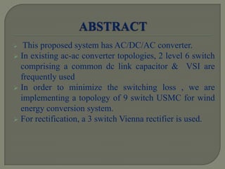

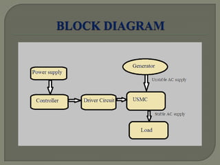
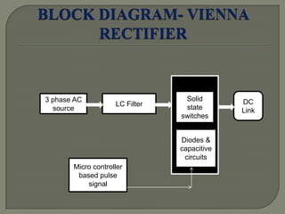
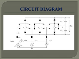
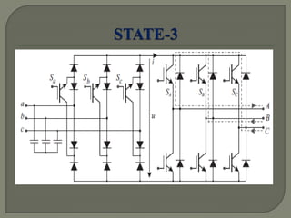
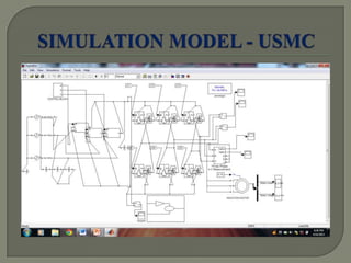
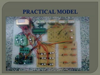
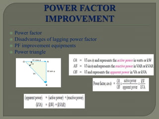
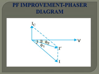
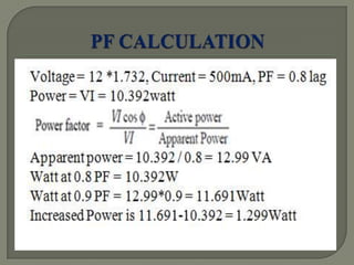
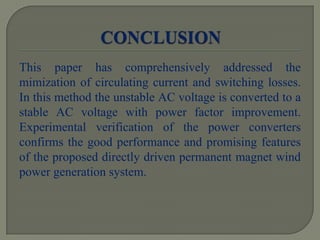


This paper proposes a novel integrated AC/DC/AC converter for direct drive permanent magnet wind power generation systems. It aims to reduce switching losses and minimize circulating current in the power converters. The proposed system uses 9 switches compared to 24 in existing systems, reducing switching losses. A Vienna rectifier and 6-switch VSI inverter are used. Experimental results confirm the improved performance over existing systems, including power factor improvement, reduced harmonics, and improved overall efficiency.


![Electric drives [ned mohan 2001 (scanned) 470pág]](https://cdn.slidesharecdn.com/ss_thumbnails/electricdrivesnedmohan2001-scanned470pg-121224050928-phpapp01-thumbnail.jpg?width=640&height=640&fit=bounds)