瑞侃工具包电缆终端-阿克巴交易
케이블 종단-거
TERMINAZIONE DEL CAVO - AKBAR TRADING
TERMINACIÓN DE CABLE - AKBAR TRADING
KABELABSCHLUSS
TERMINACIÓN DE CABLE
KABLO SONLANDIRMA
瑞侃工具包电缆终端-阿克巴交易
케이블 종단-거
TERMINAZIONE DEL CAVO - AKBAR TRADING
TERMINACIÓN DE CABLE - AKBAR TRADING
KABELABSCHLUSS
TERMINACIÓN DE CABLE
KABLO SONLANDIRMA
SPS High Voltage Cable Termination Kit List (Typical) - Three Core Cables
XLPE EPR HV Termination Kits
Anti-track heat shrink 3 core tubes x 3
Stress control heat shrink 3 core tubes x 3
Yellow stress relief tape for screen ends x 3
3 core heat shrink cable breakout boot x 1
Red mastic sealing tape x 1
Cable cleaning and de-greasing wipes x 3
Box, label, jointing instructions x 1
HV Termination Kits Optional Extras, 3 Core 6.6-7.2kV - Solderless Earth Kit for Copper Tape Screen Cables, Insulating Bushing Boots (Straight, Right Angled, Universal), HV Cable Glands for SWA Cable (Bolt-on Top Hat), Outdoor Armour Earthing Kit, Outdoor Stand-off Brackets + Insulators, High Voltage HV Cable Lugs (Crimp or Mechanical Shearbolt Lugs).
SPS High Voltage Heat Shrink Cable Termination Kits, 6.6-7.2kV - Testing
SPS high voltage heat shrink termination kits for 3 core HV cables (XLPE and EPR) are Tested and Certified to latest International Test Standards as outlined in Cenelec standards HD 628 S1 and 629.1 S2 : 2006 - high voltage cable termination kit testing also encompasses VDE 0278 and IEC 60502.
Heat shrink cable joints to suit PVC, EPR (BS6883) and XLPE (BS5467) multi-core cables up to 3.3kV - the heat shrink cable joint comprises of adhesive lined connector insulation tubes, heavy duty steel wire armour earth cage, armour support rings and clamps and an outer thick wall adhesive lined heat shrink tube.
SPS Heat Shrink Cable Joints & Cable Terminations - Quality Performance Testing : Shrink Polymer Systems heat shrink cable joints and cable termination kits are tested to BS7888 which incorporates Cenelec Standards HD 628 S1 and 629.1 S2 : 2006, DIN VDE0279 and IEC60502.
RAYCHEM SAUDI ARABIA LTD. (TYCO ELECTRONICS) |AKBAR TRADING EST. SAUDI ARABIA...AKBAR TRADING
te connectivity saudi arabia
TYCO TERMINATION KIT IN ALL VOLTAGE
Raychem terminations for polymeric and MIND
paper insulated cables from 7.2 kV up to 36 kV
System Designer
케이블 종단-거-瑞侃工具包电缆终端-阿克巴交易
ชุด การเลิกจ้าง
RAYCHEM SAUDI ARABIA LTD. (TYCO ELECTRONICS)
11kV-33kV Medium Voltage Heat Shrink Cable Joints & Cable Terminations
11kV and 33kV heat shrink cable joints and cable terminations for medium voltage power cables - SPS heat shrink cable joints and cable terminations are suitable for installation at indoors and outdoors in the Middle East countries, this includes salt laden and dusty atmospheres associated with the Middle East oil, gas and petrochemical industries. Cable terminations and cable joints are suitable for XLPE and paper insulated single core and three 3 core cables of 11kV and 33kV voltages, 3 phase, 50HZ type electrical systems with highest system voltages of 12kV and 36kV. Cable joints are suitable for connecting two XLPE insulated cables of same size or dissimilar sizes and for transition between XLPE and paper insulated lead covered (PILC) medium voltage cables.
Modern underground power cables are sophisticated assemblies of insulators, conductors and protective materials. Within these components are sensors, which enable cable operators to monitor conditions along the cable in real time.
The condition of the cable insulation is usually monitored through the following two main methods:
Loss tangent measurements
Partial discharge (PD) measurements
Explains MOLEX - facts and figures, Global Reach, Diagnostic Imaging, Patient Monitoring, Premise Networks in India, key factors to be considered for Right cabling system for health care Environments and applications. For more information visit: http://www.transformhealth-it.org/
En este webinar se abordan los fundamentos de la puesta a tierra, el detalle del cálculo y funcionamiento de los electrodos empleados con este fin, la resistencia y distribución del potencial superficial de distintos tipos de electrodos (de superficie, picas, mallado y en cimentación), el conductor de tierra, el borne de puesta a tierra, las líneas y los conductores de protección.
Ponente : Manuel Llorente es Ingeniero Técnico Industrial y Licenciado en Ciencias Físicas. Ha desarrollado su carrera profesional en Pirelli Cables y Sistemas, actual Prysmian. Fue director de formación en dicha empresa y desde 1995 trabaja como consultor y formador para diversas entidades, en particular ABB y Prysmian. Realizó una contribución fundamental en la redacción del Reglamento Electrotécnico de Baja Tensión en España. Es autor de numerosos libros: Manual de Cables Eléctricos Aislados, Prevención de Riesgos Laborales en Trabajos Eléctricos, Introducción a la Fibra Óptica, entre otros.
25kV Cable Joints & Cable Terminations
3M Cold Shrink High Voltage Cable Joints and Cable Terminations carry Network Rail approvals for 6.35/11kV, 25kV and 19/33kV polymeric power cables. Prysmian 25kV single core power cables are used to carry 25kV electrical power supplies from Network Rail track-side switching stations to the overhead line equipment on A.C. electrified lines. T&D UK provide on-going 25kV cable jointer training either in house or on site for 3M Cold Shrink joints and terminations.
High Voltage Rail Cable Joints & Cable Terminations - 6.35/11kV, 12.7/22kV and 19/33kV cables distribute three phase A.C. electrical power supplies at nominal system voltages of 11kV, 22kV and 33kV to Network Rail traction substations on D.C. electrified lines. 25kV two core concentric cables are mainly used to deliver 25kV single phase electrical power supplies, typically, to Network Rail feeder stations on A.C. electrified lines. 25kV single core cables are mainly used to carry 25kV electrical power supplies from Network Rail track-side switching stations to the overhead line equipment on A.C electrified lines - T&D stock heat shrink and cold shrink cable joints and terminations for all these rail cable applications.
E1EX~QS Barrier Gland for Steel And Aluminium Armoured Cable
Features and Benefits
For use indoors, outdoors and hazardous areas with unfilled hygroscopic multicore cables.
Two part handling, no loose parts.
Captive Cone and Cone Ring provides an armour clamp and earth bond for steel wire armour and aluminium armour.
Instantly mixed and injection Resin.
Resin forms 100% barrier seal around the individual cores of the cable.
Prevents gas and moisture transmitting down cable.
Prevents explosive gases transmitting down cable.
The pipe sprayer consists of two air motors. One drives the body around the
central axis and the second drives the cup. The cup motor is set at an angle
into the body, thus as the cup revolves and body rotates a wobble motion is
set up generating a spray pattern inside the pipe. This wobble-
head action produces a reciprocating
fan pattern which enables coating to reach
the back edges formed by pit etc., in corroded
pipes. This avoids having to go through
the pipe in two directions allowing one coat
application.
Isolation Procedures for Safe Working on Electrical Systems and Equipment by the JIB | solation Procedures for Safe Working on Electrical Systems and Equipment
This chart shows the safe isolation procedure that you should use when working on electrical systems and equipment.
You'll receive a printed copy of this from your Training Provider, but it's also here as a handy reference to keep electronically.
THE RULES OF SAFE ISOLATION ARE:
Obtain permission to start work (a Permit may be required in some situations)
Identify the source(s) of supply using an approved voltage indicator or test lamp
Prove that the approved voltage indicator or test lamp is functioning correctly
Isolate the supply(s)
Secure the isolation
Prove the system/equipment is DEAD using an approved voltage indicator or test lamp
Prove that the approved voltage indicator or test lamp is functioning correctly
Put up warning signs to tell other people that the electrical installation has been isolated
Once the system/equipment is proved DEAD, work can begin
Uploaded by THORNE & DERRICK LV HV Jointing, Earthing, Substation & Electrical Eqpt | Explosive Atmosphere Experts & ATEX IECEx.
THORNE & DERRICK based in the UK are international distributors of LV, MV & HV Cable Installation, Jointing, Substation & Electrical Equipment.
Since 1985, T&D have established an international reputation based on SERVICE | INTEGRITY | TRUST.
Contact us for 3M, ABB, Alroc, AN Wallis, CATU, Cembre, Centriforce, CMP, CSD, Elastimold, Ellis Patents, Emtelle, Euromold, Filoform , Furse, Lucy Electric & Zodion, Nexans, Pfisterer, Polypipe, Prysmian, Roxtec, Sicame, WT Henley.
Dev Dives: Train smarter, not harder – active learning and UiPath LLMs for do...UiPathCommunity
💥 Speed, accuracy, and scaling – discover the superpowers of GenAI in action with UiPath Document Understanding and Communications Mining™:
See how to accelerate model training and optimize model performance with active learning
Learn about the latest enhancements to out-of-the-box document processing – with little to no training required
Get an exclusive demo of the new family of UiPath LLMs – GenAI models specialized for processing different types of documents and messages
This is a hands-on session specifically designed for automation developers and AI enthusiasts seeking to enhance their knowledge in leveraging the latest intelligent document processing capabilities offered by UiPath.
Speakers:
👨🏫 Andras Palfi, Senior Product Manager, UiPath
👩🏫 Lenka Dulovicova, Product Program Manager, UiPath
Slack (or Teams) Automation for Bonterra Impact Management (fka Social Soluti...Jeffrey Haguewood
Sidekick Solutions uses Bonterra Impact Management (fka Social Solutions Apricot) and automation solutions to integrate data for business workflows.
We believe integration and automation are essential to user experience and the promise of efficient work through technology. Automation is the critical ingredient to realizing that full vision. We develop integration products and services for Bonterra Case Management software to support the deployment of automations for a variety of use cases.
This video focuses on the notifications, alerts, and approval requests using Slack for Bonterra Impact Management. The solutions covered in this webinar can also be deployed for Microsoft Teams.
Interested in deploying notification automations for Bonterra Impact Management? Contact us at sales@sidekicksolutionsllc.com to discuss next steps.
JMeter webinar - integration with InfluxDB and GrafanaRTTS
Watch this recorded webinar about real-time monitoring of application performance. See how to integrate Apache JMeter, the open-source leader in performance testing, with InfluxDB, the open-source time-series database, and Grafana, the open-source analytics and visualization application.
In this webinar, we will review the benefits of leveraging InfluxDB and Grafana when executing load tests and demonstrate how these tools are used to visualize performance metrics.
Length: 30 minutes
Session Overview
-------------------------------------------
During this webinar, we will cover the following topics while demonstrating the integrations of JMeter, InfluxDB and Grafana:
- What out-of-the-box solutions are available for real-time monitoring JMeter tests?
- What are the benefits of integrating InfluxDB and Grafana into the load testing stack?
- Which features are provided by Grafana?
- Demonstration of InfluxDB and Grafana using a practice web application
To view the webinar recording, go to:
https://www.rttsweb.com/jmeter-integration-webinar
Search and Society: Reimagining Information Access for Radical FuturesBhaskar Mitra
The field of Information retrieval (IR) is currently undergoing a transformative shift, at least partly due to the emerging applications of generative AI to information access. In this talk, we will deliberate on the sociotechnical implications of generative AI for information access. We will argue that there is both a critical necessity and an exciting opportunity for the IR community to re-center our research agendas on societal needs while dismantling the artificial separation between the work on fairness, accountability, transparency, and ethics in IR and the rest of IR research. Instead of adopting a reactionary strategy of trying to mitigate potential social harms from emerging technologies, the community should aim to proactively set the research agenda for the kinds of systems we should build inspired by diverse explicitly stated sociotechnical imaginaries. The sociotechnical imaginaries that underpin the design and development of information access technologies needs to be explicitly articulated, and we need to develop theories of change in context of these diverse perspectives. Our guiding future imaginaries must be informed by other academic fields, such as democratic theory and critical theory, and should be co-developed with social science scholars, legal scholars, civil rights and social justice activists, and artists, among others.
Builder.ai Founder Sachin Dev Duggal's Strategic Approach to Create an Innova...Ramesh Iyer
In today's fast-changing business world, Companies that adapt and embrace new ideas often need help to keep up with the competition. However, fostering a culture of innovation takes much work. It takes vision, leadership and willingness to take risks in the right proportion. Sachin Dev Duggal, co-founder of Builder.ai, has perfected the art of this balance, creating a company culture where creativity and growth are nurtured at each stage.
PHP Frameworks: I want to break free (IPC Berlin 2024)Ralf Eggert
In this presentation, we examine the challenges and limitations of relying too heavily on PHP frameworks in web development. We discuss the history of PHP and its frameworks to understand how this dependence has evolved. The focus will be on providing concrete tips and strategies to reduce reliance on these frameworks, based on real-world examples and practical considerations. The goal is to equip developers with the skills and knowledge to create more flexible and future-proof web applications. We'll explore the importance of maintaining autonomy in a rapidly changing tech landscape and how to make informed decisions in PHP development.
This talk is aimed at encouraging a more independent approach to using PHP frameworks, moving towards a more flexible and future-proof approach to PHP development.
UiPath Test Automation using UiPath Test Suite series, part 3DianaGray10
Welcome to UiPath Test Automation using UiPath Test Suite series part 3. In this session, we will cover desktop automation along with UI automation.
Topics covered:
UI automation Introduction,
UI automation Sample
Desktop automation flow
Pradeep Chinnala, Senior Consultant Automation Developer @WonderBotz and UiPath MVP
Deepak Rai, Automation Practice Lead, Boundaryless Group and UiPath MVP
Accelerate your Kubernetes clusters with Varnish CachingThijs Feryn
A presentation about the usage and availability of Varnish on Kubernetes. This talk explores the capabilities of Varnish caching and shows how to use the Varnish Helm chart to deploy it to Kubernetes.
This presentation was delivered at K8SUG Singapore. See https://feryn.eu/presentations/accelerate-your-kubernetes-clusters-with-varnish-caching-k8sug-singapore-28-2024 for more details.
GraphRAG is All You need? LLM & Knowledge GraphGuy Korland
Guy Korland, CEO and Co-founder of FalkorDB, will review two articles on the integration of language models with knowledge graphs.
1. Unifying Large Language Models and Knowledge Graphs: A Roadmap.
https://arxiv.org/abs/2306.08302
2. Microsoft Research's GraphRAG paper and a review paper on various uses of knowledge graphs:
https://www.microsoft.com/en-us/research/blog/graphrag-unlocking-llm-discovery-on-narrative-private-data/
Software Delivery At the Speed of AI: Inflectra Invests In AI-Powered QualityInflectra
In this insightful webinar, Inflectra explores how artificial intelligence (AI) is transforming software development and testing. Discover how AI-powered tools are revolutionizing every stage of the software development lifecycle (SDLC), from design and prototyping to testing, deployment, and monitoring.
Learn about:
• The Future of Testing: How AI is shifting testing towards verification, analysis, and higher-level skills, while reducing repetitive tasks.
• Test Automation: How AI-powered test case generation, optimization, and self-healing tests are making testing more efficient and effective.
• Visual Testing: Explore the emerging capabilities of AI in visual testing and how it's set to revolutionize UI verification.
• Inflectra's AI Solutions: See demonstrations of Inflectra's cutting-edge AI tools like the ChatGPT plugin and Azure Open AI platform, designed to streamline your testing process.
Whether you're a developer, tester, or QA professional, this webinar will give you valuable insights into how AI is shaping the future of software delivery.
"Impact of front-end architecture on development cost", Viktor TurskyiFwdays
I have heard many times that architecture is not important for the front-end. Also, many times I have seen how developers implement features on the front-end just following the standard rules for a framework and think that this is enough to successfully launch the project, and then the project fails. How to prevent this and what approach to choose? I have launched dozens of complex projects and during the talk we will analyze which approaches have worked for me and which have not.
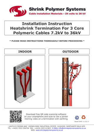
1. Installation Instruction
Heatshrink Termination For 3 Core
Polymeric Cables 7.2kV to 36kV
* PLEASE READ INSTRUCTIONS THOROUGHLY BEFORE PROCEEDING *
UNITS E3 CROWN WAY CROWN PARK INDUSTRIAL ESTATE RUSHDEN NORTHANTS NN10 6FD
TEL: +44(0) 1933 356758 FAX: +44(0) 1933 413821 E-MAIL:info@shrinkpolymersystems.co.uk
WEB: www.shrinkpolymersystems.co.uk
INDOOR OUTDOOR
ISSUE DATE: 21.02.17
Download free QR code scanning software
on your smartphone and scan to see a jointer
training video on a termination with earthing
2. VOLTAGE
INDOOR
L
OUTDOOR
L
X
7.2kV 650mm 700mm
12kV 650mm 700mm LENGTH OF LUG
17.5kV 650mm 700mm BARREL + 5mm
24kV 700mm 800mm
36kV 800mm 900mm
Remove Outer Cable Sheath:
3 Core Cable With Armour
If the cable is armoured, bonding of the armours must be completed using the appropriate
armour earthing kit.
A) For indoor terminations (cable end box) - Order kits Ref: SPS 180, SPS 193 *
B) For outdoor terminations (pole top) - Please advise conductor size and voltage.
2
* SPS 180 - 16-95mm at 7.2 to 17.5kV
2
SPS 193 - 120-300mm at 7.2 to 17.5kV
(For other voltages see selection chart in general catalogue)
IMPORTANT NOTICE TO PURCHASER:- Sellers and Manufacturere’s only obligation shall be to replace such quantity of the product proved to be defective. Neither the Seller nor
Manufacturer shall be liable for any injury, loss or damage, direct or consequential, arising out of the use or inability to use the product. Before using, User shall determine the
suitability of the product for his or her intended use and User assumes all risk and liability whatsoever in connection therewith.
Table 1
General Fitting Instructions
* It is highly recommended that a tool suitable for the removal of the
semi-conductive screen is used to provide a reliable discharge free
termination screen point. See our website for training videos.
* Use a propane gas torch with a soft flame
* Avoid a pencil like blue flame which is caused by unregulated supply
* Keep the flame on the move to ensure even shrinkage of all the
materials and also helps to reduce scorching
* Ensure that all components are kept clean and grease free during
installation
* Allow to cool before applying any mechanical strain
Note:- Dimension “L” is a guide only. The actual
length is determined by the overall geometry of the
equipment.
3. 1. Installation
Prepare the cable as shown.
Note:- The “L” dimension should not be
longer than the distance between bushing
centres and base plate.
De-grease and abrade the cable for a
distance of 100mm below the outer
sheath cut.
Note:- User may wish to alter bedding
and armour dimensions to suit the type of
gland/earthing arrangement to be used.
2. Screen Preparation
Copper Wire Screen
Apply one layer of sealant tape around the
outer cable sheath 30mm below the
sheath cut.
Bend back each screen wires and press
them into the sealant tape. Apply another
layer of tape over the bent back wires.
Twist together to form a conductor and
bond to a suitable earth point.
Note:- If cable has copper screen wires
on each core, bend these back and press
into the mastic tape. Just like the overall
copper screen wires, twist together and
bond to earth.
Copper Tape Screen
Secure the earth braids to the copper tape
screens so that the solder block is
positioned upon the cable bedding. A turn
of mastic sealant tape should be applied
beneath and on top of the solder block.
If a constant force spring is used to
connect the earth braids, the spring
should preferably be positioned above the
fingers of the breakout boot.
These braids will either be bonded to the
earth gland or other suitable earth point.
30mm
SEALANT TAPE
ROLL
SPRINGS
SEALANT TAPE
COPPER
BRAIDS
COPPER TAPE
SCREEN
Bushing centre
100mm
Armours
100mm
Bedding
L
X
100mm
Fig 1
Fig 2
Fig 3
4. Remove the copper tape screen to length
A+X as indicated in Table 2.
Note:- If the cores are to be crossed the
copper screen should be removed after
the initial setting of the cores.
It may be necessary to temporarily secure
the copper tapes to prevent them from
unwinding.
3. Conductive Layer Treatment
Extruded Conductive Screen Layer
Remove the semi-conductive screen layer
using a suitable tool to dimension B+X as
indicated in Table 2.
Note:- It is very important that the
screen is removed leaving a clean straight
cut and that no scoring or damage is done
to the primary insulation. We highly
recommend the use of approved screen
removal tools (see our website for tools
and demonstration videos). It is good
practice to flame brush the primary
insulation and conductive screen cut, this
has the effect of removing any minor
surface irregularities or burrs that may be
present.
Apply Stress Control Tape
De-grease the insulation and screen using
the solvent tissues provided.
Remove the release paper from the yellow
stress control tape. Stretch to approx.
50% width and apply the tape around the
end of each core screen. Extend onto the
primary insulation by 10mm and about
5mm onto the copper tape screens.
Note: It may not be necessary to use all
of the tape supplied.
B
10mm
5mm
COPPER TAPE
SCREEN
YELLOW STRESS
CONTROL TAPE
X
A
B
Fig 4
Fig 5
Fig 6
Table 2
Voltage
7.2kV
12kV
17.5kV
24kV
36kV
130mm
185mm
240mm
310mm
500mm
A B X
110mm
165mm
220mm
290mm
480mm
Lug Barrel
Length
+ 5mm
5. 4. Stress Control Tubes
Position the stress control tubes onto each
core so that the bottom of each tube
extends past the yellow mastic by a
maximum of 10mm.
Starting at the end closest to the cable
crutch, Shrink each tube one at a time
keep the flame on the move to ensure an
even wall thickness.
5. Installing Cable Lugs
Remove the insulation from each core to
the X dimension in Table 1.
Install cable lug and remove any burrs or
sharp points that may be present.
Preheat each Lug and wrap two layers of
Red Sealant Tape over the Lug barrel and
extend onto the Insulation by approx
10mm. Ensure the Tape is applied as
shown. Important:- use more tape to
build up the diameter to ensure tube
recovers upon it and creates a moisture
seal.
6. Installing The Breakout Boot
Slide the three legged boot over the cores
and push down into the crutch of the
cable. Shrink from the shoulder of the
breakout and down to the cable sheath,
then from the shoulder to the cores.
Apply a turn of red sealant tape around
each breakout turret as shown.
7. Installing The Anti-Track Tube
Position the anti-track tubes so that they
cover the turrets of the breakout boot and
the barrels of the lugs.
Starting from the cable crutch area,
Shrink the tubes in place. Keeping the
flame moving to ensure an even wall
thickness, ensure the tubes are fully
recovered and wrinkle free.
Allow the tubes to cool to hand hot and
trim at the lug end with a sharp knife if
necessary.
ROLL
SPRINGS
X
ANTI-TRACK
TUBE
RED SEALANT
TAPE
Fig 7
Fig 8
Fig 9
6. Indoor Terminations
To ensure long term performance of
medium voltage terminations, certain
separation distances are required as
indicated in Table 3.
Note:- Bushing protection boots will be
required for the majority of installations.
If it is necessary to cross the cores, the
cross MUST be in a screened area as
shown.
8. Installation Of Rain Sheds
On outdoor terminations the sheds should
be fitted from the bottom up as indicated
in the drawing opposite.
Indoor 36kV terminations are supplied
with one shed per phase and four sheds
per phase for outdoor.
Table 3
NUMBER OF SHEDS PER PHASE
VOLTAGE INDOOR OUTDOOR
7.2kV - 1
12kV - 2
17.5kV - 2
24kV - 3
36kV 1 4
Table 4
The first shed should be fitted at a
distance 200mm from the lower edge of
the anti-track tube to the edge of the
shed. All subsequent sheds should be
fitted at a distance of 80mm from edge to
edge.
Note:- It is advisable not to position rain
sheds at the top of stress control tubes,
re-position if necessary.
d
E
d
AIR CLEARANCE TO
LOCAL SPEC
80mm
200mm
d = SEE
TABLE 4
Fig 10
Fig 11
Fig 12
Distance (d) Phase/Phase
& Phase/Ground
Top of Stress Control Tube
To Bottom of Lug Barrel
Voltage d=(mm) E
7.2kV 15mm
12kV 20mm
17.5kV 20mm
24kV 40mm
36kV 50mm
30mm
50mm
75mm
95mm
250mm
7. MIN BENDING
RADIUS r = 15xD
D
Inverted Connections
If a termination is to mounted for
connection from above the equipment i.e
in the inverted position, sheds should be
installed through 180° as shown
Cable Bending Radius
During installation care should be taken
not to over bend the cable. In cold
condition it may be necessary to gently
heat the cable to prevent damage whilst
bending.
Fig 13
Fig 14