Download to read offline
![© 2023, IRJET | Impact Factor value: 8.226 | ISO 9001:2008 Certified Journal | Page 590
COMPENSATION OF FAULT RESISTANCE IN DISTANCE RELAY FOR LONG
TRANSMISSION LINE
Misbah Riyaz1 , Er Baljit Kaur2
Post Graduate Student,Electrical Engineering Dept,IET Bhaddal Punjab India.Assistant professor Electrical
Engineering Dept IET Bhaddal Punjab India
---------------------------------------------------------------------***---------------------------------------------------------------------
Abstract - By designing and simulating this project using
the software PSCAD, it will show us how long transmission
line distance protection behaves when faced with a fault
resistance problem.
In distance relaying, fault resistance is a crucial factor. If
ignored, it could result in the internal flaws causing distance
relays to malfunction. However, as a result of the
overreaching occurrence, the unbalanced nature of loads
and the asymmetry of lines can impact the effectiveness of
the distance protection operation. Distance protection
should possess the ideal quality of operating within faults
that are included in the protection zone in order to carry
out its function flawlessly and error-free. The project
incorporates a new numerical distance relaying technique
that is suggested to improve accuracy of these constraints
and efficiency via fault resistance estimate in the distance
protection process. This is accomplished by measuring the
impedance from the relaying point to the fault point for
various values of fault resistance for various types of faults
[1] and finding the current & voltage at the relay position.
Key Words: PSCAD, DISTANCE RELAYING ,CURRENT
ANDVOLTAGE RELAY SYSTEM
1.INTRODUCTION
It is necessary for the transmission lines to be protected
by extensive and intricate protection measures in order to
keep the impact of power outages on the affected region
and time to a minimum. a safety measure implemented
before the power system becomes unstable. Modern
distance relays offer high-speed fault eradication. They are
employed in situations where overcurrent relays slow
down and when it is challenging to grade time overcurrent
relays for complex networks. At 220 kV,132 kV, and 400
kV, they are utilized to safeguard transmission and sub
transmission lines. Distance protection would not be
commercially feasible for 11 kV distribution lines and 66
kV transmission lines, thus over current relays are
employed instead.
1.1 BASIC PRINCIPLE DISTANCE PROTECTION
A distance relay has the capacity to identify a problem
within a predetermined range along a power cable or
transmission line from its location. Each power line has a
resistance and reactance per kilometer that are related to
the design and construction of the line, so the overall
impedance willdepend on the length of the line. In order
to comparecurrent and voltage, a distance relay looks at
these two values in light of Ohm's law.
International Research Journal of Engineering and Technology (IRJET) e-ISSN: 2395-0056
Volume: 10 Issue: 09 | Sep 2023 www.irjet.net p-ISSN: 2395-0072
Given that a transmission line's impedance is inversely
proportional to its length, a relay that can measure a line's
impedance up to a specific point (the reach point) is suited
for distance measurement. In order to provide
discrimination for faults that may occur in various line
sections, distance relays are designed to only work for
faults that occur between the relay position and the
predefined (reach) point.
Divide the voltage at the relaying point by the observed
current to understand the fundamentals of distance
protection. A comparison between the reach point
impedance and the estimated apparent impedance is
made. When measured impedance is lower than reach
point impedance, it is presumed that a fault exists on the
line between the relay and the reach point
1.2 BASIC OF FAULT RESISTANCE
The four components of fault resistance are electrical
equipment resistance, ground resistance, tower footing
resistance, and arc (flashover at line insulator) resistance.
An arc resistance is added to the fault path in the event of
a flashover from phase to phase or phase to ground.
Higher voltages significantly increase the arc resistance.
The impedance of the line is raised by the addition of the
arc resistance, resulting in a higher overall impedance that
is seeded by the distance relay. When there are ground
faults, the earth's resistance enters the fault route as well.
The resistance of the ground includes the resistance of the
tower, the resistance of the tower footing, and the earth
return path. Fault resistance is the result of adding arc and
earth resistance together. Since there is no earth
resistancein the case of phase-to-phase failures, the fault
resistance simply consists of arc resistance.
The Warrington formula [3] yields the arc resistance.
Rarc = 29 * 103 * l / I1.4
where I is the fault current in amps and l is the arc'slength
in meters.](https://image.slidesharecdn.com/irjet-v10i9109-240108141851-6dd45034/75/COMPENSATION-OF-FAULT-RESISTANCE-IN-DISTANCE-RELAY-FOR-LONG-TRANSMISSION-LINE-1-2048.jpg)
![© 2023, IRJET | Impact Factor value: 8.226 | ISO 9001:2008 Certified Journal | Page 591
For phase faults, l will initially equal the conductor
spacing, and for ground faults, it will equal the distance
between the phase conductor and the tower. The cross
winds that typically accompany a lightningstorm lengthen
the arc.An electrical arc is an electrical breakdown that
occurs when a medium's dielectric strength is exceeded;
the kind of medium can affect the dielectric strength.
While certain electrical arcing, such as that produced by
welding,
plasma cutting, and arc lamps, may be controlled, thepower
system should avoid arcing that is not under control. These
characteristics could also cause significant harm, though, if
no safety precautions aretaken to identify the arc. Electric
arcs on overhead wires can happen when the insulating
element separating the conductor from the support breaks.
Such insulating elements include pins, strains, and others
based on their voltage and the conductor's weight and
support. In addition, when two phases of a line come into
contact, arcing may also occur. For instance, the wind
energy nearby causes the Phase R conductor and Phase Y
conductor to come into contact. Direct contact between a
conductor and the earth or another grounded object, such
as a downed conductor, will result in an arc. Because not all
of the electrical power produced is supplied to the
designated loads, the arcing phenomena also results in a
loss of energy for the power companies. When a foreign
object comes into touch with a conductor, power is lost
while being delivered to the load. As a result of the tiny
current that passes through nearby items that provide high
impedance in the current path to the ground, the typical
relay, such as a distance relay, struggles to identify faults
when they first arise. The issue arises when an arcing fault
occurs close to the zone's end of the relay's range [7].
2. PROBLEM STATEMENT
Circuit breakers, switchboard panels, low voltage
distribution boards, electrical appliances, and overhead
wires are just a few of the places where thefault resistance
might happen. In terms of overhead lines, single line to
ground fault is the most frequent fault connected to the
presence of resistance. The resistance of the arc (flashover
at line insulator), the resistance of the tower footing, and
the resistance of the ground make up the fault resistance.
This type ofproblem, in particular, causes the conventional
relayto experience high impedance arcing faults. due to the
large impedance present in the current path, it is
International Research Journal of Engineering and Technology (IRJET) e-ISSN: 2395-0056
Volume: 10 Issue: 09 | Sep 2023 www.irjet.net p-ISSN: 2395-0072
challenging
to identify the fault current. Flashovers are a component of
the majority of frequent overhead line defects, including
insulator failures and lightning strikes. Most impedance-
type distance to fault locator algorithms were in some way
by the non- linearity in the network caused by these arcs.
However, the majority of fault locators developed today
are based on the supposition that the defect has a
constant resistance. Since fault resistance compensation is
required for long transmission lines, it has become vital to
research the phenomenon of fault resistance on overhead
lines.
3 OBJECTIVE OF THE PROJECT
This project's primary goal is to analyze the impact of
transmission line fault resistance dependent on fault
distance. In addition, this study intends to compute fault
resistance using a mathematical formula and identify the
origins of the occurrence of fault resistance on
transmission lines. Finally, this project was developed to
compensate for fault resistance on the mho protection
system based on the problem statement provided [1].
4 SCOPE OF THE PROJECT
Transmission line distance protection issues are brought
on by fault resistance. First off, this project will only
concentrate on single phase to ground faults, and not on
any other kinds of faults. The next sort of protection
strategy to be used is the polarized mho protection
scheme. Modeling the failure resistance in transmission
line-based schemes using the PSCAD/EMTDC software is
successful. A straightforward power system with fault
resistance can be used for the PSCAD simulations. permit
analysis of several fault resistance types, including
equipment resistance, ground resistance, and tower
footing resistance.
5 LITERATURE SURVEY
5.1 DISTANCE PROTECTION OF TRASNMISSION LINE
We must fully comprehend the operating concepts and
some issues linked with the protection schemes used on
transmission lines in order to adequately address the
issues related to fault resistance on transmission lines
with distance protection scheme.If the fundamental ideas
behind this plan are understood, required adjustments to
the current distance protection plan can be made to
address the issue caused by transmission line fault
resistance. In general, there are three major types of
transmission line protection schemes. The first is an
overcurrent type protection strategy, followed by a
differential type protection scheme and a last one known
as a distance protection method. Pilot protection refers to
the usage of a communications link for protection
issues between ends of the transmission line in the context
of power system protection. Distance protection
schemes can be either non-pilot or pilot. Knowing the
state of the line at both ends is advantageous when using
pilot schemes. Phase comparison relaying method is one of
the three types of approaches, or differential protection
scheme. This differential approach examines the phase of
the currents at both ends of the line to determine if
there is a fault in the middle, as opposed to using](https://image.slidesharecdn.com/irjet-v10i9109-240108141851-6dd45034/75/COMPENSATION-OF-FAULT-RESISTANCE-IN-DISTANCE-RELAY-FOR-LONG-TRANSMISSION-LINE-2-2048.jpg)
![© 2023, IRJET | Impact Factor value: 8.226 | ISO 9001:2008 Certified Journal | Page 592
Figure 1 : Stepped Distance Chracteristics of distance Relay
The most important factor in the power system is thefault
International Research Journal of Engineering and Technology (IRJET) e-ISSN: 2395-0056
Volume: 10 Issue: 09 | Sep 2023 www.irjet.net p-ISSN: 2395-0072
clearance time for any type of protective strategy. When
protecting a transmission line utilizing non-pilot distance
protection techniques, it is vital to rely on stepped zones
of protection because impedance measurements are
imprecise. With more than one zone, a distance protection
technique enables to protect any specific piece of
transmission line. Zone 1 protection immediately resolves
Close in faults.About 80– 90% of the railway is protected
under Zone 1. If a defect occurs at the far end of the line, the
relay may not be able to determine whether it is actually on
that segment of line or an adjacent section based on the
accuracy of the impedance measurements. Therefore, it is
desirable to allow for a delay in tripping for faults that
the relay determines are within the upper limits of zones 1
and 2, or between 120 and 150 percent of the length of the
line in question. The line's third zone serves as a backup for
the lines next to it. By allowing for trip delays on zone 2 and
zone 3 faults, zone 1 protection of the adjacent line can be
operated during this period. The fault will be fixed in zone 2
if it is located at 95% of the line in question.
This plan's inclusion of a delay ensures adequate
coordination and aids in the endeavor to prevent shutting
down more line than is required to repair the fault. One
relay can offer both primary and backup protection
features thanks to distance protection schemes.
Figure above displays Distance relays with stepped
distances divide the entire line into three zones for
protection. Since the line is fed from both sides, 6 relays
are employed to safeguard it from damage. R1,R3, and R5
are used in the same direction as the figure, while R2, R4,
and R6 are used in the other direction. The distance
protection relaying not only offers the protected line main
protection but also time-delayed backup protection for
the protected line as well as for nearby lines.
distance relaying principles. There are numerous more
protection system options outside the phase
comparison protection scheme, some of which
(distance relaying techniques) rely on impedance
measurements. Stepped distance protection is a need for
all techniques that consider impedance measurements.
All other distance protection programs that are not
pilot-based program are subject to the same type of notion.
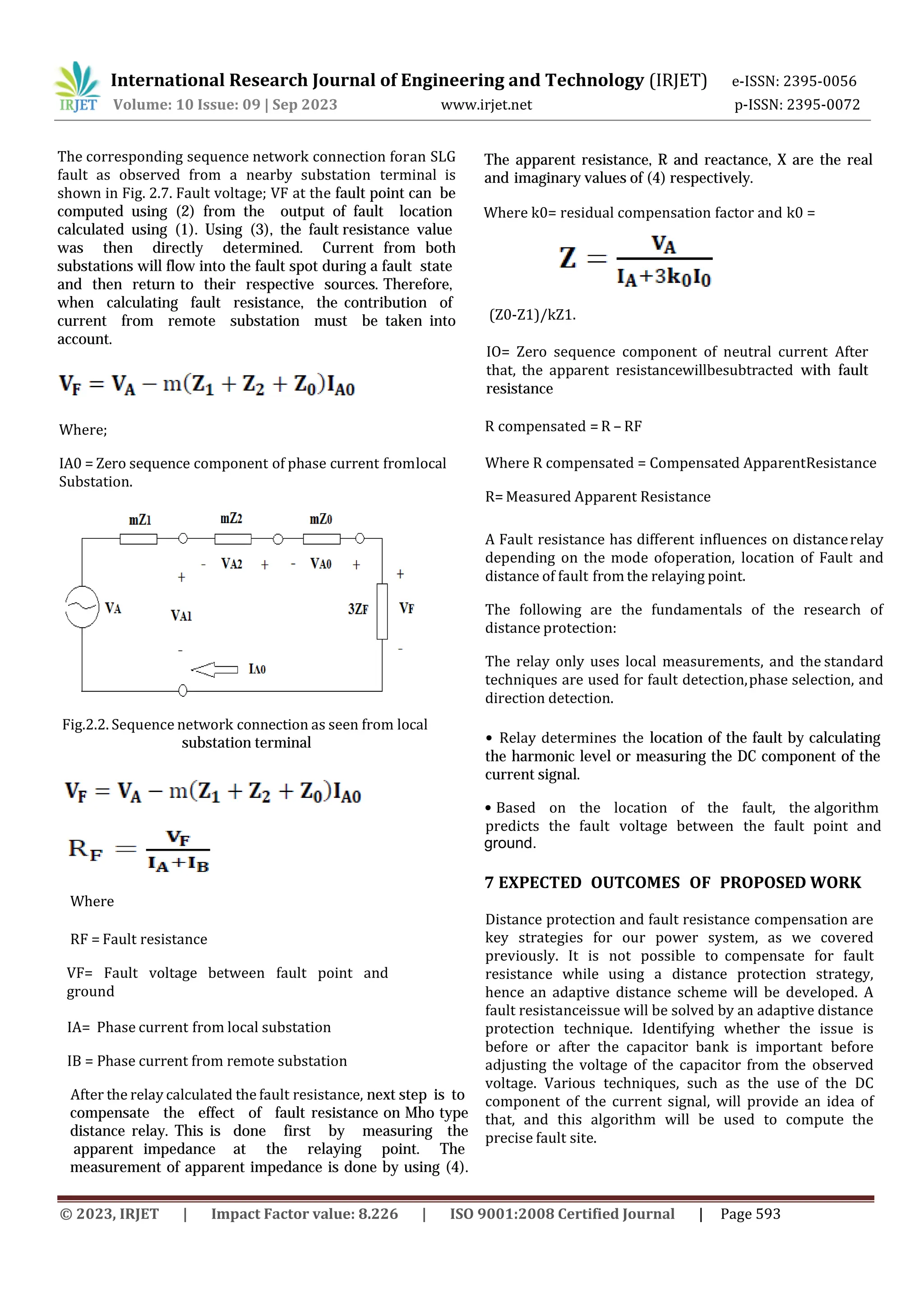
6 PROPOSED WORKS
6.1 OVERVIEW OF PROPOSED WORKS
We must enhance the distance protection strategy in
6.2 Alogirithim of Proposed Scheme
The fault site is estimated using a two-terminal technique
[1]. The source impedance parameters are not required by
the algorithm, and the estimated fault location is unaffected
by the fault resistance value. Single Line to Ground (SLG)
fault location computation is represented by Equation (1),
and the
SLG fault situation at a phase line is depicted in Fig 2 Where
M= Fault of Location Estimation Z1= Postitive sequence
impedance Z2= Negative sequence impedance Z0 = zero
sequance impedance VA= Phase to ground voltage for local
substation VB = Phase to ground voltage for remote
substation IA = Phase current from local substation IB =
Phase current fromremote substation
Single line to ground fault Fig 2.1
order
to address the challenges caused by fault resistance when
it is utilized for long transmission lines, as was stated
above. The impedance of the transmission line between
the fault point and the relay point is used as the basis
for the distance protection scheme's operation.
Impedance is measured by determining the ratio of the
voltage and current at the relay point. If fault resistance is
present in the fault loop, it is important to subtract
the fault resistance from the observed impedance in
order to measure impedance accurately in transmission
lines. The primary goal of this work is to identify the
defect.](https://image.slidesharecdn.com/irjet-v10i9109-240108141851-6dd45034/75/COMPENSATION-OF-FAULT-RESISTANCE-IN-DISTANCE-RELAY-FOR-LONG-TRANSMISSION-LINE-3-2048.jpg)

![8.4 SIGNAL PROCESSING STAGE
Figure 4 Input Data Processing Stage Systems
The signal is being processed at this point. A few of the
parts required for the distance relay system are shown in
Figure 4.7. Fast Fourier Transform is used for the "Online
Frequency Scanner" rather than Discrete Fourier
Transform. Instead of using DFT, this FFT offers a quicker
and more effective data processing method. The voltage and
current signals contain fading DC components with higher
order frequency and lower order frequency when a
transmission line has a fault. This FFT component's job is to
retrieve the source signal's fundamental magnitudes and
phases. The extracted data will thenbe turned into positive,
negative, and zero sequence using "Sequence Filter" once
the signal has been extracted using FFT. In order to be used
for a mho impedance relay, the transformed data will then
be combined once again according to their phase.
International Research Journal of Engineering and Technology (IRJET) e-ISSN: 2395-0056
Volume: 10 Issue: 09 | Sep 2023 www.irjet.net p-ISSN: 2395-0072
8.5 PROTECTION STAGE SCHEME
Figure 5 Polarized Mho Protection Scheme Stage
As illustrated in Figure 5, the system requires six
protection units in order to detect all fault types including
line-ground, double line-ground, line-line, and three-phase
faults. Three of these units measure line to ground
impedance, while the remaining three measure line to line
impedance. Therefore, all of the input used in the PSCAD
program comes from the extracted databased on the Signal
Processing Stage, and the unit components are already
available. The "mho circle" will then be connected to each
unit's output. If the OR gateoutput will be showing “1” than
there is the reach of the distance relay and ifthe OR gate
output will be showing “0” than there is fault out of relay
characteristic.
9 CONCLUSION
A common transmission line protection strategy is distance
protection. Nonlinear properties of the mho relay cause a
number of issues with impedance measurement in the
distance protection system when it is employed with fault
resistance in the transmission line. Instead of using the
traditional distance protection technique, an adaptive one
should be employed to address this issue. During adaptive
distance protection, the fault resistance linecan be adjusted
in angle while the fault resistance is calculated and made
up for using the line impedance. Relay characteristics can
be altered if fault resistancechanges line impedance. Relay
can adjust for changes in line impedance and function in
accordance with its genuine impedance value in an
adaptive distance protection scheme.
10 REFERENCES
[1] G.ZIEGLAR(2018) Effect of fault resistance on the
operating behaviorof distance relay
[2] M.R.ARJAOE(2017) A practical first- zone distance
relaying algorithm forlong parallel transmission lines
[3] Z.y.xu(2016) First-zone distance relaying algorithm of
parallel transmission lines for single-phase to ground
faults
[4] R. Dubey (2015) An Extreme Learning Machine based
fast and accurate adaptive distance relayingscheme
[5] E.Sorrentino 2014 Comparison Of Five Methods of
Compensation for the ground Distance Function and
Assesment of their effect on the Resistive Reach in
quadrilateral Characteristics
[6] Ying Zhong, Xiaoning Kang, Zaibin Jiao, Zengchao
Wang, and Jiale Suonan, Member, IEEE Transactions
ON Power Delivery, VOL. 29, NO. 4, August 2014 on “A
Novel Distance Protection Algorithm for the Phase-
Ground Fault”
© 2023, IRJET | Impact Factor value: 8.226 | ISO 9001:2008 Certified Journal | Page 595](https://image.slidesharecdn.com/irjet-v10i9109-240108141851-6dd45034/75/COMPENSATION-OF-FAULT-RESISTANCE-IN-DISTANCE-RELAY-FOR-LONG-TRANSMISSION-LINE-6-2048.jpg)
![[7] M.P. Thakre, V.S.Kale,Jan 2014 International Joutnal of
Advances in Engineering & Technology ,Electrical
Engineering Department, V.N.I.T,Nagpur,M.S.,India on
“Distance protection for Long Transmissionline using
PSCAD”.
International Research Journal of Engineering and Technology (IRJET) e-ISSN: 2395-0056
Volume: 10 Issue: 09 | Sep 2023 www.irjet.net p-ISSN: 2395-0072
[8] Amit N. Patel, Chirag D. Chauhan, Vipul N. Rajput,
Assistant Professor, Dr.Jivraj Mehta Institute of
Technology, Power Delivery, International Journalfor
Scientific Research & Development, On Volume:1, Oct.
2013 “ A New Fault Resistance Compensation
Scheme for Distance Relaying Application ".
[9] Muhd Hafizi Idris, Mohd Saufi Ahmad, Ahmad Zaidi
Abdullah, Surya Hardi School of Electrical System
Engineering University Malaysia Perlis, Arau, Perlis,
IEEE 7th International Power Engineering and
Optimization Conference, Langkawi, Malaysia, 3-4
June 2013"Adaptive Mho Type DistanceRelaying
Scheme withFault Resistance Compensation".
[10] R.C.D SANTOS (2011)Transmission Lines distance
protection using artificialneutral networks
[11] J.UPENDAR (2011) Comprehensive adaptive distance
relaying scheme forparallel transmission lines
[12] R. H. Salim, D. P. Marzecand, and A. S. Bretas, Student
member, IEEE Transactions Power Delivery, vol. 26
April 2011 "Phase distance relaying withfault-
resistance compensation forunbalanced systems".
[13] M. Resener and A. S. Bretas Student member , IEEE
Transactions Power Delivery., vol. 23 July 2008
"Ground distance relaying with fault-resistance
compensation for unbalanced systems".
[14] B.BHALJA (2007) An adaptive distance relaying
scheme using radial basis function neural network
[15] M.sanaye (2006) Adaptive distance protection
scheme with quadrilateral characteristic for
extremely high- voltage/ultra-high-voltage
transmissionline
[16] Noha Abed Al-bary Al-jawady, M Sc. Thesis
University Mosul, 1998, “Effect of Fault Resistance on
thePerformanceof Mho Relays”.
[17] K .K LI (1997) Ideal operating region of digital
distance relay under high resistance earth fault.
[18] J. Roberts, A. Guzman, E.O.Schweitzer, III Schweitzer
Engineering Laboratories, Inc, Pullman, Washington,
Oct-1993 PowerTech on “Z = V/I does not make a
distance relay”.
© 2023, IRJET | Impact Factor value: 8.226 | ISO 9001:2008 Certified Journal | Page 596](https://image.slidesharecdn.com/irjet-v10i9109-240108141851-6dd45034/75/COMPENSATION-OF-FAULT-RESISTANCE-IN-DISTANCE-RELAY-FOR-LONG-TRANSMISSION-LINE-7-2048.jpg)

This document discusses distance protection for long transmission lines and the impact of fault resistance. It begins with an introduction to distance relaying and the issues caused by fault resistance. It then discusses the objectives of analyzing how fault resistance affects protection at different fault distances. The document proposes a new algorithm to estimate fault location and resistance using voltage and current measurements from two terminals. The algorithm compensates for fault resistance in mho-type distance relays by measuring apparent impedance and subtracting the estimated fault resistance. This improves the accuracy of distance protection for faults with resistance on long transmission lines.


