Download to read offline
![Samuel A. Isaac, Olajube Ayobami, Awelewa Ayokunle, Utibe Bassey
http://www.iaeme.com/IJMET/index.asp 891 editor@iaeme.com
1. INTRODUCTION
During the early years, long transmission lines and overhead lines were an “indissoluble
binomial” for the AC Power Systems [1]. Faults are considered as the total breakdown or loss
of synchronism of power system network which does not exclude the environmental hazards
such as electrocution and a devastating fire outbreak [2]. This means that the general belief as
at the time was purely of the reliance on overhead lines for transmission of signals. This left
the use of High Voltage (HV) and Extra High Voltage (EHV) insulated cables to be dedicated
to DC submarine links. Faults are however meant to be located and cleared as fast as possible
to forestall further loss of revenue and discomfort from the customer end [3]. The underground
cable system was first considered in Northern Germany as early as 1870 and was implemented
on the telegraph system [4]. This was generally as a result of a heightened regard for
environmental conditions, the increasing hindrances encountered on the overhead lines, and
increased reliability on the high-quality extruded insulations among other reasons.
The replacement of these overhead cables and lines by underground ones or inculcating a
hybrid system (i.e. merging of the overhead lines and the underground cables) has been
considered by power systems operators in the power sectors in various countries.
The underground cable system installations are mostly carried out for economic reasons
amongst others. Some of the advantages of its installation are highlighted below.
1. A greatly reduced probability of damage from weather conditions e.g. lightning, winds,
freezing, among others.
2. Underground cable system provides a reduced range of Electromagnetic Fields (EMF)
emission [4].
3. Less components are installed alongside the underground cables. This is the opposite in
the use of overhead lines as more components are installed alongside for safety,
maintenance or repair.
4. Underground cable system reduces the probable hazard that could have been imposed
on flying aircraft and wildlife.
5. There are reduced chances of conductor theft, sabotage and illegal connections [5].
6. In environmental conscious countries, underground cable system provides spaces for
large trees to be planted and grow freely.
The advantages of underground system process can, in some cases, outweigh its
disadvantages generally. One of the most observed and more practical disadvantage of
underground system process is the fault location difficulty whenever it occurs.
2. LITERATURE REVIEW
Unlike the overhead cables, the underground cables are made to curb electromagnetic induction
and to withstand various soil conditions. In order to serve its purpose, the underground cables
are manufactured in thick protective layers, and with varying diameters depending on the depth
of earth it is buried, and its volts-amp rating. Generally, underground cables for transmission
are of less diameter than those for distribution. The anatomy of underground cables is shown
below in fig. 1](https://image.slidesharecdn.com/ijmet1003092-190627133546/75/ARDUINO-MICROCONTROLLER-BASED-UNDERGROUND-CABLE-FAULT-DISTANCE-LOCATOR-2-2048.jpg)
![Arduino Microcontroller Based Underground Cable Fault Distance Locator
http://www.iaeme.com/IJMET/index.asp 892 editor@iaeme.com
Figure 1 Parts of an underground power cable
The main part of the underground cable is the core conductor, which transmits the electrical
energy from the source point to the load. Underground cables have now been made for different
applications and at different voltage levels and are still under research and development. The
selection of conductor is relative, depending on manufacturer’s discretion. It could either be
aluminum or copper in solid or stranded form. Also, its application could influence the choice
of conductor, based on its flexibility, economics, physical property, shape, voltage, ampacity
and other factors [6]. Conductors are made to carry current under various conditions and
withstand pulling stresses during cable laying [7].
In order to prevent electrical field concentration, a semiconductor interface is provided
between the conductor and the insulation. This is usually black in color. This is the conductor
screen (or shield). It works synergistically with the insulation shield to make for a uniform
cylindrical surface for even distribution of electrical stress [8].
There are different types of insulations for underground power cables, such as Ethylene
Propylene Rubber (EPR), Cross-Linked Polyethene (XLPE), paper insulated and Tree-
Retardant Polyethylene (TRPE) compounds. The insulation is used to insulate a high voltage
working conductor from the shield, when working at earth potential [7]. The insulation has to
be able to insulate electrical field under rated voltages, and during overvoltage. This therefore
implies that the size of insulator varies directly as voltage rating.
The insulation screen is also a semiconductor. Apart from aiding of even distribution of
electrical stress, the insulator screen borders electric field within the cable, reduce dangers
arising from shocks, curb radio interference and protect voltage induced by cable when
connected to overhead lines [9]. The outer part of the shield is usually connected to ground at
one point. It is either metallic or non-metallic; drain wires or concentric neutral wires. The
metallic sheath (or concentric neutral conductors) is the metallic part of the insulation screen
and serves as a conduction path for neutral return current [10].
The conductive tape and water tight tape work simultaneously to ensure an improvement in
electrostatic shield and serves as a moisture barrier. The outermost layer and the first point of
protection for the cable is the cable jacket. It provides thermal, mechanical, environmental and](https://image.slidesharecdn.com/ijmet1003092-190627133546/75/ARDUINO-MICROCONTROLLER-BASED-UNDERGROUND-CABLE-FAULT-DISTANCE-LOCATOR-3-2048.jpg)
![Samuel A. Isaac, Olajube Ayobami, Awelewa Ayokunle, Utibe Bassey
http://www.iaeme.com/IJMET/index.asp 893 editor@iaeme.com
chemical protection. The outer jacket could be made of different compounds like polyethene,
nylon, and a number of other plastics. Some cable manufacturers prefer the use of sheath or
armor instead of a jacket, as this provides better protection than a jacket.
2.1. Ageing phenomenon of underground cables
As cable ages, deterioration is inevitable. Most utility components, especially underground
cables, have higher failure rates as time passes [11]. This deterioration is caused by thermal,
mechanical, electrical and environmental factors or combination of any of these factors [12].
The underground cable eventually fails due to persistence of the acting factor.
The activation of any of these factors could cause either an intrinsic aging, or an extrinsic
aging. Intrinsic aging occurs when the aging mechanism changes the bulk properties of the
material used for insulation. On the other hand, extrinsic aging occurs when the aging
mechanism causes degradation of the cable [8]. This degradation comes about by the persistent
presence of defects, contaminants, protrusions or voids and their intercourse with any of the
aging mechanisms [13].
Electrical stresses tend to be the most dominant ageing factor. Consequently, this stress
causes the underground cable to fail via partial discharge or water treeing mechanism (that is,
heightened by the presence of moisture) [8]. Water treeing activities is the major and the worst
cause of cable failures in organic extruded dielectric and cross-linked polyethene, in particular.
The cable encounters damages in its insulation in which the path of deterioration resembles a
tree. In dry insulators, the main cause of treeing is the presence of partial discharge under high
electric stress and water (or moisture) at low electrical stresses. In laminated cables, treeing is
caused by drying of oil and burning of the insulating papers, leaving carbon deposits (carbon
treeing). This forms a conductive path through the dielectric material leading to cable failure.
Generally, they are formed by the presence of moisture, impurities, contamination and electric
field over time [14]. Treeing occurs in two forms: -
1. Bow-tie treeing
2. Vented treeing.
Bow-tie trees grow from the insulation outwards towards the surface; the growth is in the
direction of the electric field and in the both directions towards the two electrodes. They exhibit
faster initial growth rate, but don’t grow so large enough to cause failure in insulation. Vented
trees grow from the surface of the polymer inwards towards the dielectric system. They also
grow in the direction of the electric field. However, they exhibit lower initial growth rate and
can grow right through the entire dielectric thickness. This type of trees tends to cause more
damage and, if not checked, lead to cable failure.
Nevertheless, reoccurring cable failures are caused by thermally aged insulation
breakdown. This is mostly observed in the paper insulated cables. Insulation losses are
increased by presence of moisture. This causes heat localization which gradually degrades the
paper insulation [10].
2.2. Underground cable faults
Faults, if not attended to, tend to cause adverse or drastic effects on the workings of power
systems in a number of ways. They cause an abnormal increase in voltage or current levels at
specific points of the system, and this rise shortens the life span of the equipment. Faults also
cause instability of the power system, causing three-phase equipment to operate abnormally.
Faults are also liable to cause dangers to personnel and could also start a fire [15]. Therefore, it
is expedient that a fault be disconnected or cleared as soon as it occurs, in order to maintain
normal working conditions of the rest of the system.](https://image.slidesharecdn.com/ijmet1003092-190627133546/75/ARDUINO-MICROCONTROLLER-BASED-UNDERGROUND-CABLE-FAULT-DISTANCE-LOCATOR-4-2048.jpg)
![Arduino Microcontroller Based Underground Cable Fault Distance Locator
http://www.iaeme.com/IJMET/index.asp 894 editor@iaeme.com
As earlier seen, lengthy transmission lines are victims of environmental topography, giving
it an increased fault probability. These faults are broadly classified to shunt and series faults.
Shunt faults, however, have higher chances of occurrence (e.g. single line-to-ground fault).
These faults can be caused by lightning, trees growing on lines, among others [14].
Generally, faults in power systems can be broadly categorized into two, which are
symmetrical faults and unsymmetrical faults. Symmetrical faults are faults that occur in a power
system without causing an imbalance of the system (i.e. the phases still maintain phase angles
of 120° between the phases). This type of faults rarely occurs and exhibits a large amount of
current flow. An example of symmetrical fault is when the three phases are short circuited to
earth [16].
Unsymmetrical faults occur on one phase or two phases. An unsymmetrical fault causes an
imbalance in the power system (i.e. the phases are no longer separated by a phase angle of
120°). They occur between phases or between phase (or phases) and ground [17].
Faults, whether symmetrical or unsymmetrical, are unsafe to the power system and
personnel alike. They are usually caused by persisting ageing mechanisms and other factors.
Some of these factors are: -
1. poor workmanship.
2. Inherent defects during manufacture.
3. Damage by improper handling.
4. National Electric Energy Testing, Research & Applications Center (NEETRAC) by
Georgia Institute of Technology estimated 42.7% of outages to faulty splices and
terminations [17].
2.3. Types of underground faults
2.3.1. Short Circuit and Earth Faults
Short circuit faults decrease impedances but increase phase angle. This, however, depends on
the distance of the fault from the source [18]. Short circuit faults closer to source reduces
impedance dramatically and increases fault current, therefore making it hazardous in nature
[19,20]. They could be as a result of a damage in the cable insulation and causes overheating
of conductors. Usually, arcing occurs at the point of fault or an area close the fault location [13].
Earth faults, on the other hand, are the most common faults in power system. This type of fault
occurs when a current carrying conductor comes in contact with the lead (or metallic) sheath,
which transfers current to the earth [21]. These faults manifest themselves in several ways.
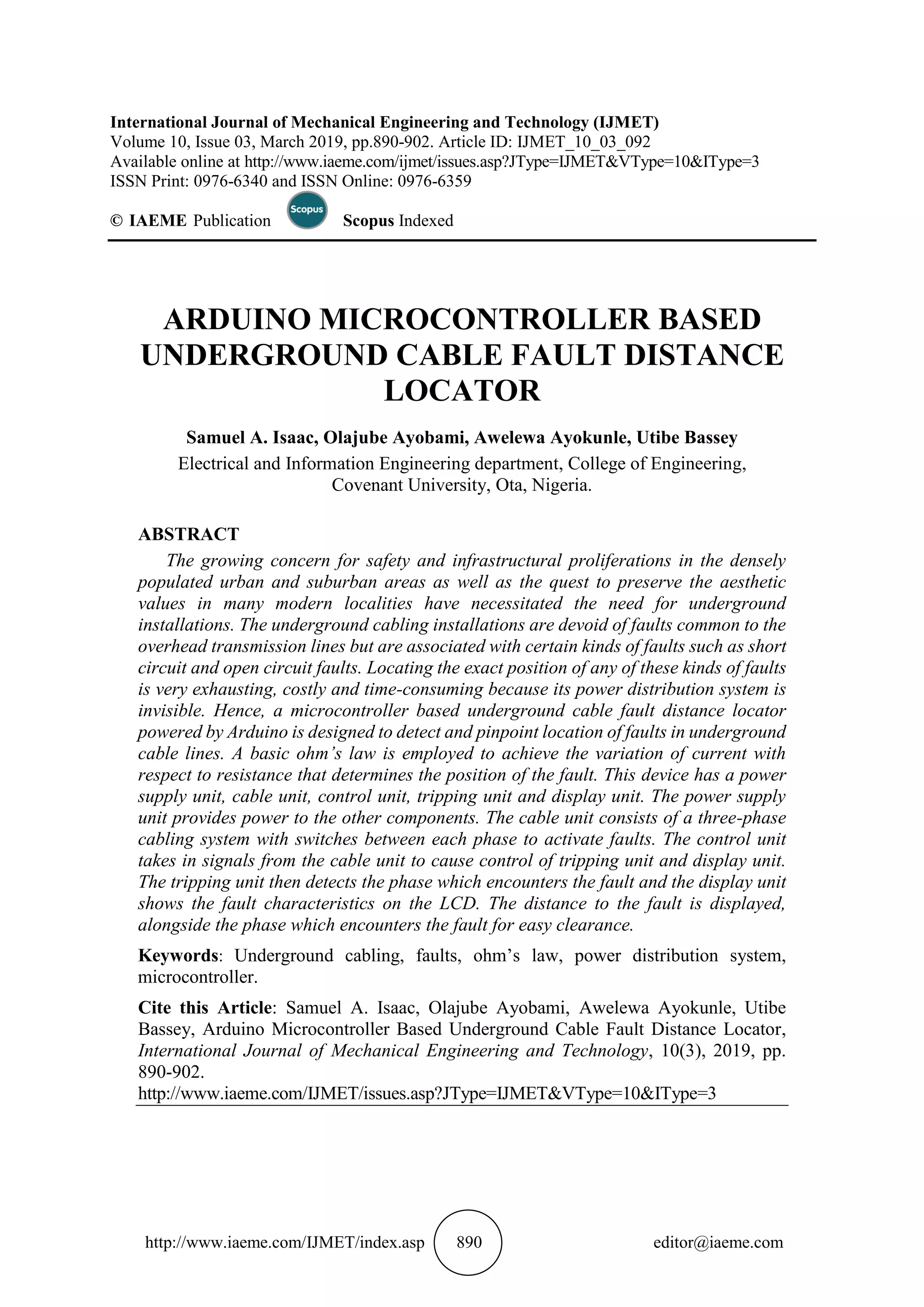
2.3.1.1. Three Phase-to-Ground
This occurs when all three phases are in contact with each other. It is exhibited by large amount
of current flow and a drastic voltage drop across the phases (very close to zero), while the
system remains balanced, as shown in fig. 2.
Figure 2 Three Phase-to-Ground fault](https://image.slidesharecdn.com/ijmet1003092-190627133546/75/ARDUINO-MICROCONTROLLER-BASED-UNDERGROUND-CABLE-FAULT-DISTANCE-LOCATOR-5-2048.jpg)
![Samuel A. Isaac, Olajube Ayobami, Awelewa Ayokunle, Utibe Bassey
http://www.iaeme.com/IJMET/index.asp 895 editor@iaeme.com
2.3.1.2. Three Phase short circuit fault
All the three phases are connected together at the fault location as shown in fig. 3, and there is
heavy current flow through conductors to the ground. The system remains balanced.
Figure 3 Three Phase short circuit fault
2.3.1.3. Line-to-Line fault
A short circuit occurs between two phases as shown in fig.4. It is exhibited by heavy current
through the two phases, while the third still supplies its load. The system gets unbalanced due
to these types of faults.
Figure 4 Line-to-Line short circuit fault
2.3.1.4. Line-to-Line-to-Ground
Fault current flows through the shorted phases and to the ground as shown in fig. 5.
Figure 5 Double Line-to-Ground short circuit fault
2.3.1.5. Single Line-to-Ground
This type of fault accounts for 95 percent of faults in power systems [18]. The load is supplied
by all three phases, but there will be a heavy flow of current to ground from the failed phase.
This fault current circulates back, returns to the neutral and then to the generator. Fig. 8 shows
the fault described.](https://image.slidesharecdn.com/ijmet1003092-190627133546/75/ARDUINO-MICROCONTROLLER-BASED-UNDERGROUND-CABLE-FAULT-DISTANCE-LOCATOR-6-2048.jpg)
![Arduino Microcontroller Based Underground Cable Fault Distance Locator
http://www.iaeme.com/IJMET/index.asp 896 editor@iaeme.com
Figure 8 Single Lint-to-Ground short circuit fault
2.4. Open Circuit Faults
These types of faults are also called ferro-resonance [18]. This ferro-resonance causes very high
voltage level across transformer windings and from line to ground. The voltage level is so high,
it could damage the insulators and windings of the transformer. However, no current flows
through the open circuit, making it less hazardous to personnel. An example of this is a loose
joint connection or a broken conductor, usually caused when cable has been stretched beyond
its limit [21]. It can also be caused by a malfunction of a protective device (e.g. circuit breaker,
fuses, etc.). Open circuit faults isolate the load side from the generation or supply side and could
cause an imbalance in the system [19].
2.5. Fault detection techniques
Faults have negative effects on power system as a whole. They constitute a major fraction of
losses in the power system [22], and also pose a hazard to instrument and personnel. Therefore,
it is necessary to locate and rectify a fault as soon as it is detected. Apart from reduced
reliability, cable faults tend to be costly. Detection of these faults quickly would, not only save
working time, but also play a part in loss of revenue for the power company [6]. Structural
changes and reviewed policies have put the power sector in a position where they give
customers quality and reliable supply of electrical power at reduced costs. This place power
companies in positions where they can condone only a very small amount of losses and also, to
optimize their maintenance culture as much as possible.
There have been permanent and fully functional methods for locating faults on overhead
distribution lines. On the contrary, this is not the case for underground distribution lines, as
methods required to perform the fault location are still in development and implementation
stages. This doesn’t stand to meant that there are no functional means by which underground
distribution cable faults could be located in the power sectors. However, researches are being
conducted to discover a means in which these faults can be located easily, in no time and with
little side effects on the service old cables [6].
Protective equipment is installed in power stations in order to clear faults or to isolate vital
equipment from adverse effects due to the fault. In the event where actions protective equipment
is unable to rectify a fault, it is necessary for skilled personnel to locate and clear the fault
manually. Basically, three steps are involved when clearing a fault;
1. Fault localization.
2. Fault detection.
3. Fault clearing.
Fault localization is the process of fault location where the entire cable is examined and a
hypothesis is made for the faulty region. Sectionalizing is a widely used method of fault
location, in which the cable is cut and spliced physically into smaller lengths in order to identify
the faulty area [19]. Fault detection aims at confirming a fault is present, meanwhile, fault
location aims at discovering the exact physical location of the fault [6].](https://image.slidesharecdn.com/ijmet1003092-190627133546/75/ARDUINO-MICROCONTROLLER-BASED-UNDERGROUND-CABLE-FAULT-DISTANCE-LOCATOR-7-2048.jpg)
![Samuel A. Isaac, Olajube Ayobami, Awelewa Ayokunle, Utibe Bassey
http://www.iaeme.com/IJMET/index.asp 897 editor@iaeme.com
When clearing a fault, it is of utmost importance that the exact location of the fault be found.
There are mainly two means of fault location;
1. Online method and
2. Offline method.
The online method employs the voltage and current levels which have been sampled, to
determine the exact location of the fault [23]. This method has its applications mainly in
underground cables as compared to overhead lines [24].
Offline method is performed with the aid of some dedicated instruments. These instruments
are used to test for the service of the cable [20]. There are two major methods used based on
offline location method.
A. Tracer method.
B. Terminal method.
Tracer method- This is the most widely used method by power stations generally. It
involves walking along the cable route. Here, fault location is identified from acoustic or
electromagnetic signals. It indicates the exact location of the fault [23,20]. Application of this
method can be seen in Tracing coil method and Sheath coil method [23].
Terminal method- it involves the identification of a range for the fault location from one
or both ends of the cable. The objective of the terminal method is to identify a general area of
the fault so as to quicken tracing process [20]. Applications of the terminal method can be seen
in Murray Bridge loop method and Impulse current method [23].
2.6. Murray Bridge Loop Method
This is one of the oldest method of underground and submarine cables localization. An end of
the defective cable is connected through a resistor pair to a voltage source. A balance
galvanometer (zero detector) is connected and the other cable end is short circuited. The
galvanometer bridge is kept balanced by adjusting P and Q [21]. An example of Murray Loop
Testing is shown in fig. 9 below.
BT1
BT2
BT3
X
R
Sound cable
Faulty cable
G
P
K2
K1
Q
F
Earth fault
A B
C D
E
Far end
Earth path
Low resistance
connection
Figure 9 Murray Bridge Loop.](https://image.slidesharecdn.com/ijmet1003092-190627133546/75/ARDUINO-MICROCONTROLLER-BASED-UNDERGROUND-CABLE-FAULT-DISTANCE-LOCATOR-8-2048.jpg)
![Arduino Microcontroller Based Underground Cable Fault Distance Locator
http://www.iaeme.com/IJMET/index.asp 898 editor@iaeme.com
Where; l = line segment of wire,
x = length of faulty cable,
RC = resistance of sound cable length,
RD = resistance of faulty cable length,
R = ratio P/Q.
RC is proportional to (l + (l – x)) = (2l – x) and RD is proportional to x. Also,
P/Q= RC / RD
R = (2l-x)/x
X = 2l/(R+1)
However, the Murray Bridge Loop method is of the assumption that only a single fault
exists along the cable length, cable resistance per unit length is uniform through the whole cable
and has lower resistance as against the high resistance of the cable [22].
3. METHODOLOGY AND SYSTEM DESIGN
The whole system can be divided into 4 basic sections: -
1. DC power supply section,
2. Cable section,
3. Controlling section and
4. The display section [20].
The mode of operation can be seen in Fig. 10 below.
Figure 10 Block diagram of the proposed system.
THE DC SUPPLY SECTION: - This is the heart of the system. It embodies the
rectification phase. 220V AC from a power supply is stepped down to 12V AC by a step-down
transformer, and this stepped down voltage is rectified by a full bridge rectifier, to convert the
AC voltage to an equivalent DC voltage value. The voltage output from this section is 15V and
5V, which are used to power other sections.
CABLE SECTION: - The cable section requires 5V DC from the rectification circuit. It
comprises of resistors to indicate cables, and push button switches to activate the short circuit
fault between the phases. The cables are represented by 4 1kΩ resistors in series for each phase
(Red, Yellow and Blue phases). Each resistor represents 1km length span. Another set of 4 1kΩ
resistors are used to cause voltage division at every 1km.](https://image.slidesharecdn.com/ijmet1003092-190627133546/75/ARDUINO-MICROCONTROLLER-BASED-UNDERGROUND-CABLE-FAULT-DISTANCE-LOCATOR-9-2048.jpg)

![Arduino Microcontroller Based Underground Cable Fault Distance Locator
http://www.iaeme.com/IJMET/index.asp 900 editor@iaeme.com
DISPLAY SECTION: - This section displays output of the control section. The LCD is
the primary display device used. It gives the status of each cable and the distance to the fault
when a fault has been activated, with the respective phase.
Cables have resistances, and therefore can be represented by a set of resistors in series.
Cables also have resistance per kilometer ratings. These become very useful when measuring
for fault distances in the cable. Any deviations in resistance for a particular length indicates the
presence of a fault in the cable [23]. The series 1kΩ resistors for voltage drop divides the three
cables into four sections, each represented as 1km. This voltage drop is used to pinpoint the
location of the fault when activated by sensing current changes [20]. This voltage drop sends a
signal to the Analog-to-Digital Converter (ADC) in the microprocessor, to develop accurate
and corresponding digital data based on calculations programmed in the source code. The relay
driver causes a trip on the affected phase, when the fault has been activated. This sends a signal
in order to determine the phase in which the fault occurred on [25]. These data are then
displayed on the LCD screen. For software simulation, a closed switch activates the short circuit
fault between two lines. The voltage drop at that point causes a change in current, and this
change sends a signal to the microprocessor for digital data analysis. The system is fully digital,
although real life applications would contain analog data and readings also.
5. RESULTS AND DISCUSSION
Table 4-1 Voltage Drop Values used by microprocessor.
S/No.
Distance of fault
occurrence (km)
Voltage across
resistor (V)
ADC Output
(*1000)
1 1km 3.35 670
2 2km 4.00 800
3 3km 4.30 860
4 4km 4.45 890
The results of the fault locations as detected by the device are shown in the table above. The
ADC output is displayed on the LCD with respect to each varying distances of the fault
locations. The power circuit is shown below;
Figure 11 The Power Circuit
The schematic diagram of the system as a whole is shown below in Fig. 11.](https://image.slidesharecdn.com/ijmet1003092-190627133546/75/ARDUINO-MICROCONTROLLER-BASED-UNDERGROUND-CABLE-FAULT-DISTANCE-LOCATOR-11-2048.jpg)
![Samuel A. Isaac, Olajube Ayobami, Awelewa Ayokunle, Utibe Bassey
http://www.iaeme.com/IJMET/index.asp 901 editor@iaeme.com
Figure 11 Schematic Diagram of the Proposed System.
5. CONCLUSION
Considerable efforts have been put into the issue of fault location in an underground cable
power infrastructure as exemplified in the covenant university, ota, ogun state, Nigeria.
However, a simple ohm’s law-based technology has been developed to easily locate faults in
an underground power cable layout and invariably helps to easily clear the faults, preserve
aesthetics, reduce time duration, drudgery, and optimize cost.
The progress made in the underground cable detector design can induce high penetration of
the underground cable technologies into the major cities of the developing countries to
minimize environmental disasters associated with overhead transmission lines.
ACKNOWLEDGEMENTS
The authors appreciate Covenant University Centre for Research, Innovation and Discovery
for supporting the publication of this research study.
REFERENCES
[1] Roberto Benato, Antonio Paolucci, EHV AC Undergrounding Electrical Power (Power
Systems), 2010.
[2] Abdulkareem A., C.O.A Awosope, A.A Awelewa “The use of three-phase fault analysis for
rating circuit breakers on Nigeria 330KV Transmission Lines”. Journal of Engineering and
Applied Sciences, 11(12): 2612-2622, 2016.
[3] Awelewa A.A, Mbamaluikem P.O, Isaac A. Samuel “ Artificial neural networks for
intelligent fault location on the 33KV Nigeria Transmission Line”. International Journal of
Engineering Trends and Technology, 54(3), 2017.
[4] [Online]. Available: http://www.emfs.info/Sources+of+EMFs/Underground/.](https://image.slidesharecdn.com/ijmet1003092-190627133546/75/ARDUINO-MICROCONTROLLER-BASED-UNDERGROUND-CABLE-FAULT-DISTANCE-LOCATOR-12-2048.jpg)
![Arduino Microcontroller Based Underground Cable Fault Distance Locator
http://www.iaeme.com/IJMET/index.asp 902 editor@iaeme.com
[5] [Online]. Available: http://www.dnaindia.com/india/report-to-curb-power-theft-
maharashtra-explores- underground-supply-network-across-state-2084774.
[6] S. Y. King, N. A. Halfter, Underground Power Cables, New York: Longman Inc., 1982.
[7] Association, National Rural Electric Cooperative, Underground Distribution System
Design and Installation Guide, Washington D.C., 1993.
[8] Butler-Purry, M. J. Mousavi and K. L, "Study of thermal aging effects on distribution
transformer solid insulation," in 34th North American Power Symposium, Tempe, AZ, Oct.
2002.
[9] J. Densley, "Ageing mechanisms and diagnostics for power cables – an overview," IEEE
Electrical Insulation Magazine, vol. 17, no. 1, pp. 14 - 22, January – February, 2001.
[10] N. Srinivas, and N. Ahmed, "Condition assessment of distribution and transmission class
voltage cable systems," in IEEE 10th International Conference on Transmission and
Distribution Construction, Operation and Live-Line Maintenance, Orlando, FL, 2003.
[11] N. H. Malik, A. A. Al-Arainy, and M. I. Qureshi, Electrical Insulation in Power Systems,
New York: Marcel Dekker, 1998.
[12] T. Sandri, Director, Cable Fault Locating Webinar. [Film]. PROTEC Equipment
Resources.
[13] "ELPROCUS," [Online]. Available: https://www.elprocus.com/what-are-the-different-
types-of-faults-in-electrical-power-systems/. [Accessed 02 03 2018].
[14] "Quora," [Online]. Available: https://www.quora.com/What-are-symmetrical-and-
unsymmetrical-faults. [Accessed 02 March 2018].
[15] B. Anderson, Director, Fault Characteristics of Power Grids. [Film].
[16] G. Ojha, A. G. Roy and R. Verma, "Underground Cable Fault Distance Locator,"
International Journal of Advance Research, Ideas and Innovations in Technology, vol. 3,
no. 2.
[17] K., Padmanaban; G., Sanjana Sharon; K., Vishnuvarthini, "Detection of Underground cable
fault using Arduino".
[18] Victory, Itodo Friday, "Design And Construction Of Digital Underground Cable Fault
Locator," University of Agriculture, Makurdi, Benue State, Nigeria, February, 2012.
[19] P.S. Pooja . M. Lekshmi, "Fault Detection and Technique to Pinpoint Incipient Fault for
Underground Cables," International Journal of Engineering Research and General Science,
vol. 3, no. 3, May - June, 2015.
[20] M. Dhekale P. , S. Bhise S. , R. Deokate N. , Prof. Survawanshi R., "Underground Cable
Fault Distance Locator," International Journal Of Innovations in Engineering Research and
Technology, vol. 2, no. 4, 2015.
[21] Sawatpipat P., Tayjasanant T., "Fault Classification for Thailand's transmission lines based
on discrete wavelet transform," in International Conference on Electrical
Engineering/Electronics Computer Telecommunications and Information Technology
(ECTI-CON), 2010.
[22] Akash Jagtap, Jayesh Patil, Bhushan Patil, Dipak Patil, Aqib Al Husan Ansari, Atul Barhate,
"Arduino based Underground Cable Fault Detection," Maharashtra, India.
[23] Abdulkareem A., C.O.A Awosope, A.U Adoghe “Power line technical loss evaluation
based online current from unbalanced faults”. Research journal of applied Sciences,
11(18): 592-607, 2016.
[24] Shunmugam R, Divya, Janani T G, Megaladevi, Mownisha P, "Arduino Based
Underground Cable Fault Detector," International Journal of Recent Trends in Engineering
and Research.
[25] Himanshu Babu, Manu Singh, Pintu Kumar, Rajat Agarwal, "Cable Fault Distance
Locator," International Journalof Scientific Research and Management Studies, vol. 3, no.
6, pp. 234-239.](https://image.slidesharecdn.com/ijmet1003092-190627133546/75/ARDUINO-MICROCONTROLLER-BASED-UNDERGROUND-CABLE-FAULT-DISTANCE-LOCATOR-13-2048.jpg)

1. The document describes an Arduino microcontroller-based device for locating faults in underground cable lines. It uses basic Ohm's law to detect faults by measuring variations in current with respect to resistance at different points along the cable. 2. The device has several units - a power supply, cable unit with switches to induce faults, control unit to process signals from the cable unit, tripping unit to detect faulty phases, and a display unit to show fault characteristics and distance on an LCD screen. 3. Common underground cable faults include short circuits, open circuits, and earth faults between phases and ground, which can be caused by insulation damage, loose connections, and other factors related to aging of cable materials over time