Downloaded 333 times

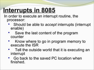
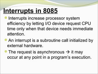
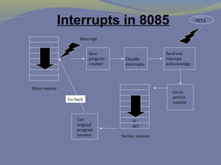
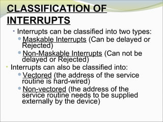
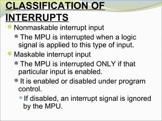
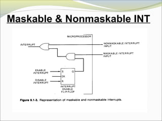
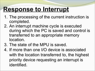
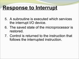
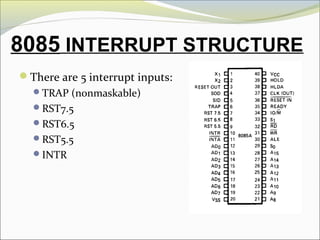
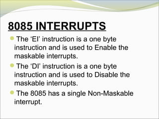
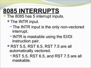
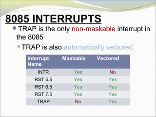
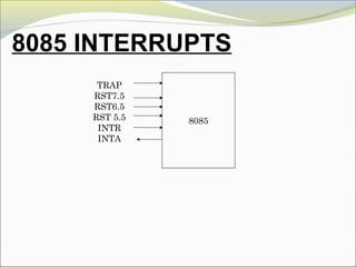
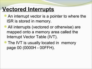
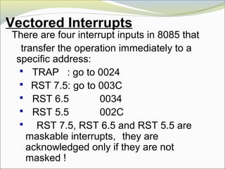
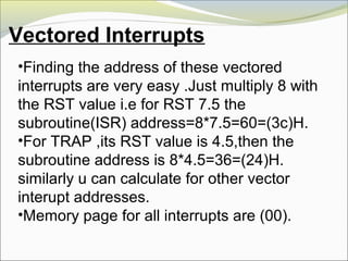
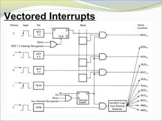
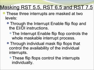
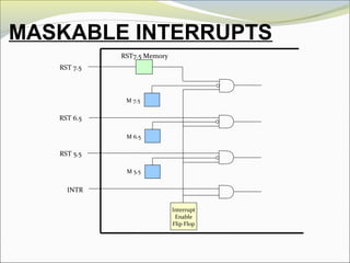
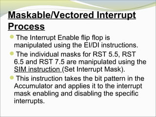
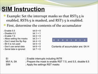
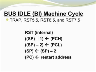
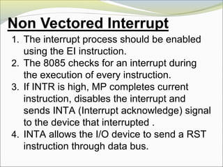
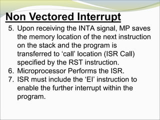
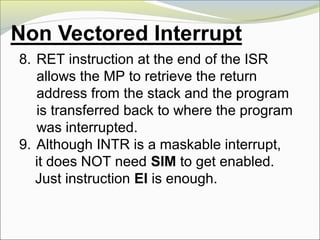
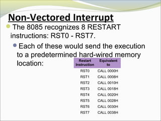
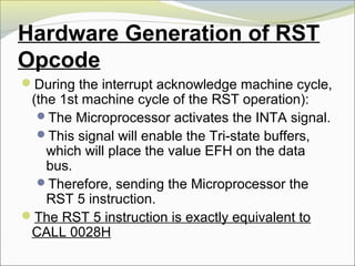
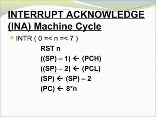
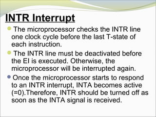
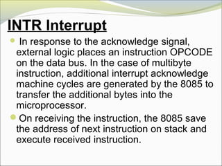
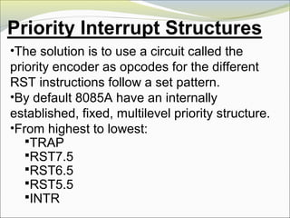
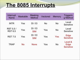

The document discusses interrupts in the 8085 microprocessor. It describes how interrupts work, including the different types of interrupts, how interrupt requests are handled, and the interrupt acknowledge process. It also covers interrupt masking, vectored interrupts, and the interrupt structures in 8085 systems.


![[Deck] What's New in Spark-Iceberg Integration via DSV2.pptx](https://cdn.slidesharecdn.com/ss_thumbnails/deckwhatsnewinspark-icebergintegrationviadsv2-260210005337-25955b12-thumbnail.jpg?width=640&height=640&fit=bounds)

