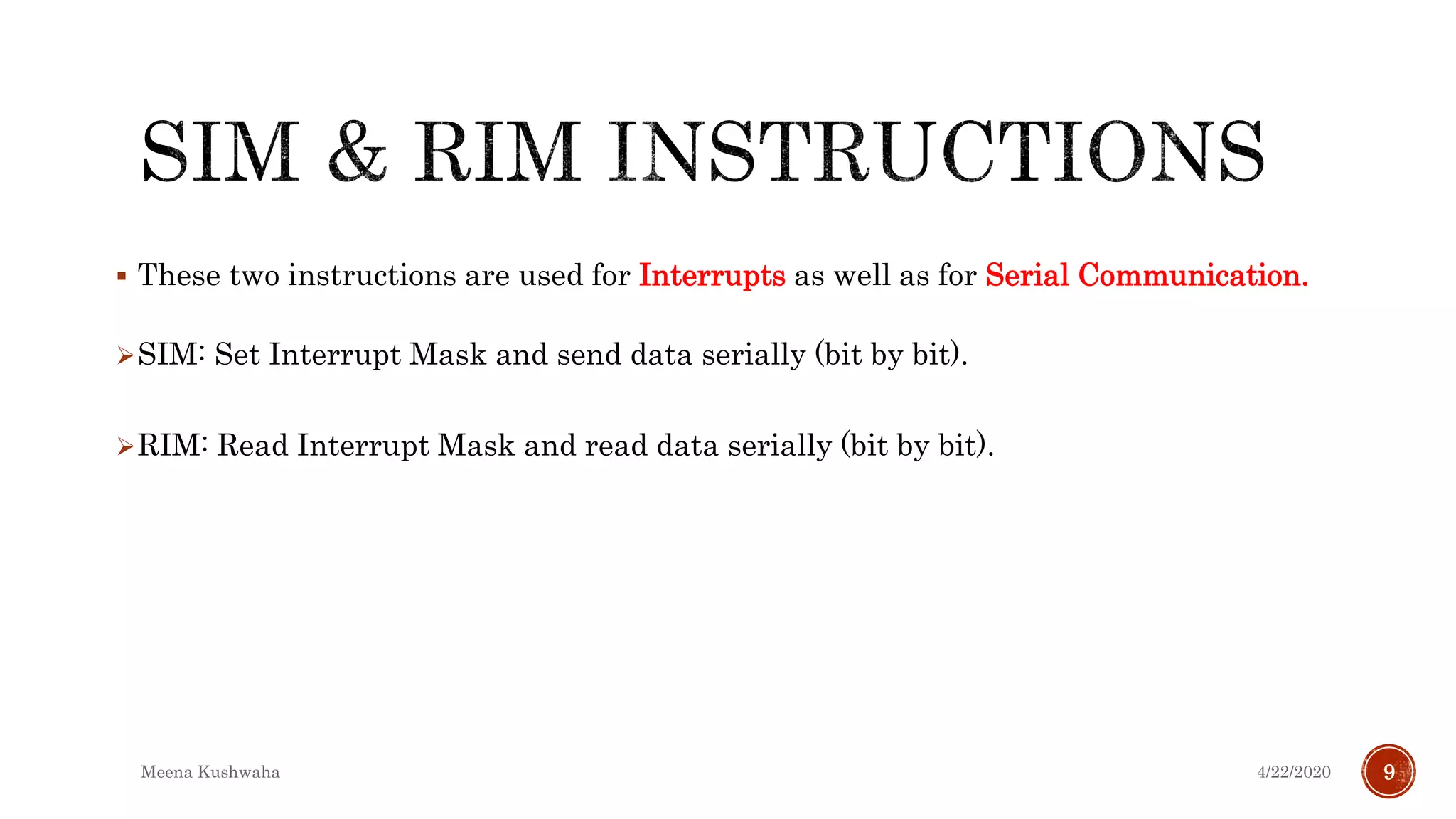
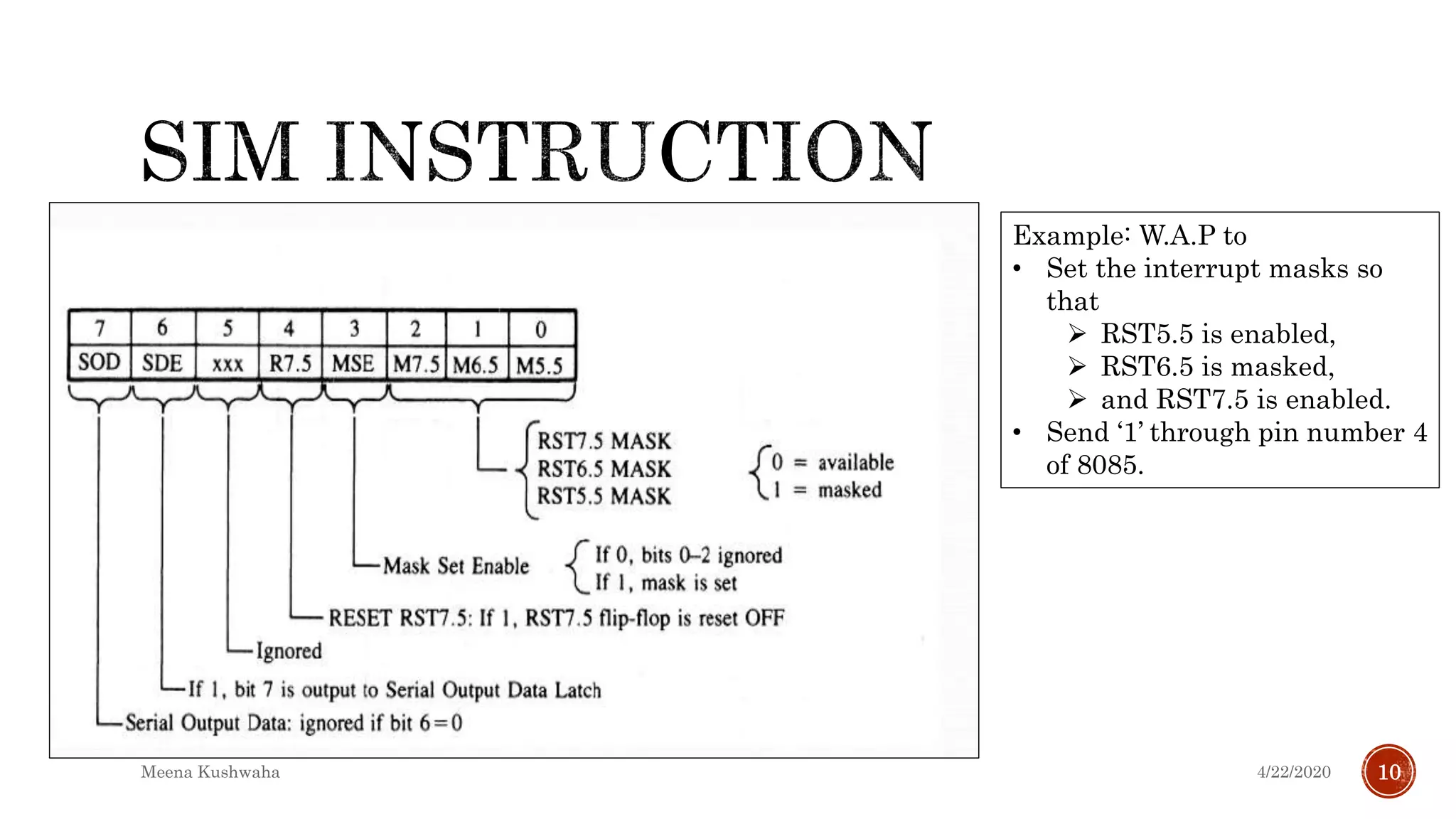
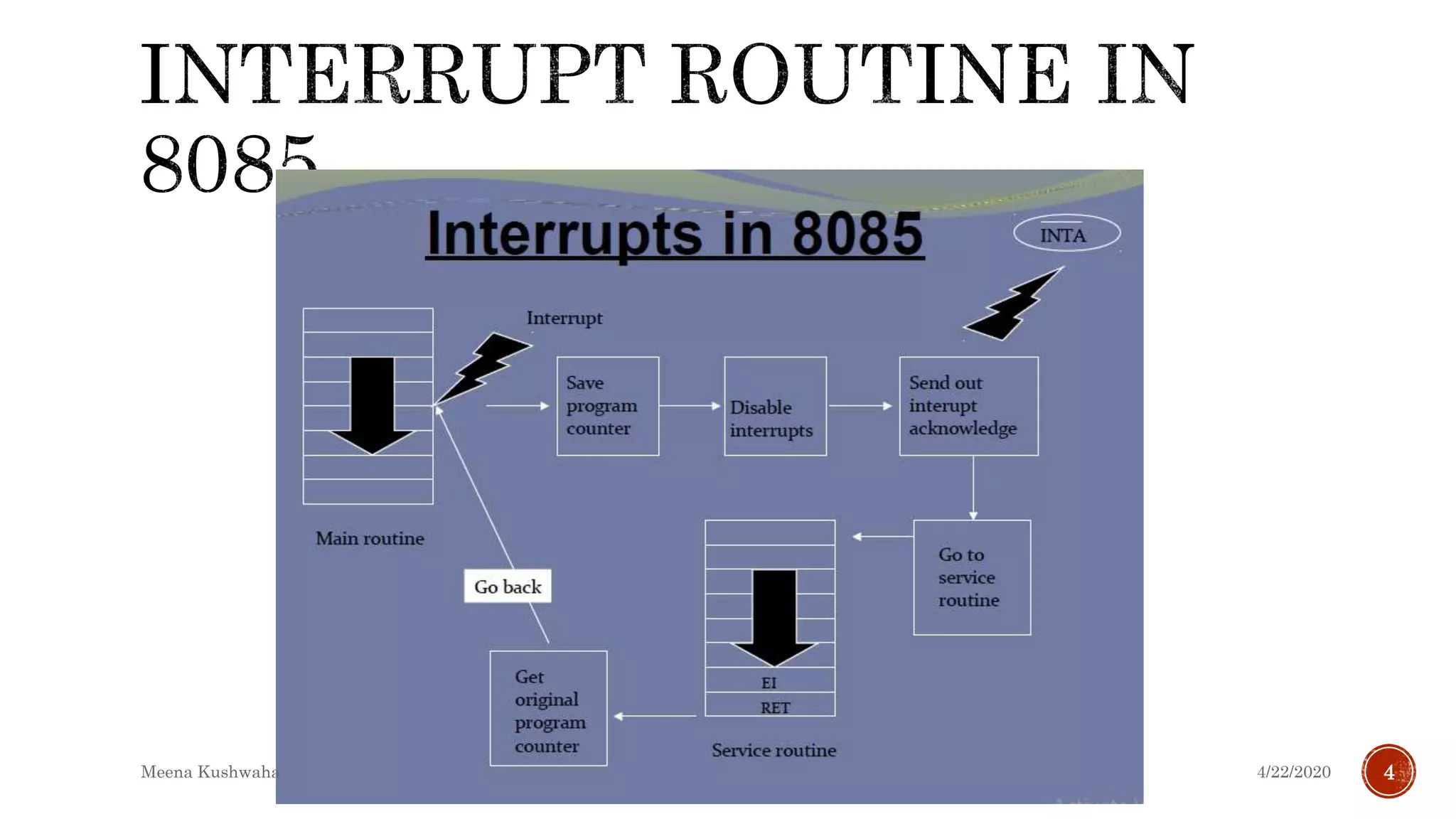
4/22/2020Meena Kushwaha
1
 To set up communication between microprocessor & I/O devices either
Polling or Interrupt method is used.
 Interrupt is an initiative taken by external device to grab the attention of
the μP.
 The process is asynchronous, can occur at any time during execution of
program.
 An interrupt is considered as an emergency signal which should be
responded by the microprocessor as soon as possible.
4/22/2020Meena Kushwaha 2
 When the Microprocessor receives an interrupt signal, it suspends
the currently executing program for a while and jumps to an
Interrupt Service Routine (ISR) to respond to the incoming
interrupt.
 Each interrupt will most probably have its own ISR.
 When the interrupt signal arrives:
1. The processor will break its routine
2. Go to a different routine (interrupt service routine)
3. Complete the interrupt service routine(ISR)
4. Come back to the “regular” routine
4/22/2020Meena Kushwaha 3
4/22/2020Meena Kushwaha 4
Interrupts can be classified into two types:
Maskable Interrupts (Can be delayed or Rejected)
Non-Maskable Interrupts (Can not be delayed or Rejected)
Interrupts can also be classified into:
Vectored : The address of the subroutine is already known to the
Microprocessor
Non-vectored (the address of the service routine needs to be
supplied externally by the device)
Interrupts can also be classified into:
Hardware Interrupt [TRAP, RST7.5, RST6.5, RST5.5,INTR]
Software Interrupt [RST n]
4/22/2020Meena Kushwaha 5
 Hardware interrupt is Asynchronous (it can occur at any
time).
 The 8085 has five hardware interrupts
(1)TRAP
(2)RST7.5
(3)RST6.5
(4)RST5.5
(5)INTR(address is supplied externally)
Interrupt Name Maskable Vectored
INTR Yes No
RST 5.5 Yes Yes
RST 6.5 Yes Yes
RST 7.5 Yes Yes
TRAP No Yes 4/22/2020Meena Kushwaha 6
 EI : one byte instruction.
This instruction is used to Enable the maskable interrupts.
 DI : one byte instruction.
This instruction is used to Disable the maskable interrupts.
 The 8085 has a single Non-Maskable interrupt, i.e. TRAP.
4/22/2020Meena Kushwaha 7
M
7.5
M
6.5
M
5.5
4/22/2020Meena Kushwaha 8
 These two instructions are used for Interrupts as well as for Serial Communication.
SIM: Set Interrupt Mask and send data serially (bit by bit).
RIM: Read Interrupt Mask and read data serially (bit by bit).
4/22/2020Meena Kushwaha 9
Example: W.A.P to
• Set the interrupt masks so
that
 RST5.5 is enabled,
 RST6.5 is masked,
 and RST7.5 is enabled.
• Send ‘1’ through pin number 4
of 8085.
4/22/2020Meena Kushwaha 10
 First, determine the contents to write in the accumulator
Enable 5.5 bit 0 = 0
Disable 6.5 bit 1 = 1
Enable 7.5 bit 2 = 0
Allow setting the masks bit 3 = 1
Don’t reset the flip flop bit 4 = 0
Bit 5 is not used bit 5 = 0
Don’t use serial data bit 6 = 1
Serial data is ignored bit 7 = 1
 Code for above setting is : CA H
 Assembly Language Program:
EI #Enable interrupts including INTR
MVI A, 0A #Prepare the mask to enable RST 7.5, and 5.5, disable 6.5
SIM #Apply the settings RST masks
1 1 0 0 1 0 1 0
4/22/2020Meena Kushwaha 11
 When RIM instruction is executed an
8-bit data is loaded in accumulator,
which can be interpreted as shown in
fig.
 RIM does the following tasks:
1. Read the interrupt mask (bit 2, 1, 0).
2. Identify pending interrupts (bit 6, 5, 4).
3. Check the Interrupt flag.
4. Receive serial input data bit (bit 7).
4/22/2020Meena Kushwaha 12
 Decode the content of Accumulator if you get 28 H after writing RIM.
0 0 1 0 1 0 0 0
4/22/2020Meena Kushwaha 13
 It is a instruction based Interrupt which is completely control by software.
 That means programmer can use this instruction to execute interrupt in main
program.
 There are 8 software interrupt available in 8085 μP that are RST 0 to RST 7.
 The vector address for these interrupts can be calculated as:
Interrupt number * 8 (in decimal) = Vector Address (in Hexa)
For e.g., Vector address for interrupt RST5 is 0028H. This vector address is stored in
Program Counter(PC).
 These instruction allow transfer of program control from the main program to
predefined service routine is also referred to as ISR (Interrupt Service Routine).
4/22/2020Meena Kushwaha 14
Interrupt Interrupt number * 8
(in decimal)
Vector Address
(in Hexa)
RST 0 0 x 8 = 0 0000 H
RST 1 1 x 8 = 8 0008 H
RST 2 2 x 8 = 16 0010 H
RST 3 3 x 8 = 24 0018 H
RST 4 4 x 8 = 32 0020 H
RST 4.5 (TRAP) 4.5 x 8 = 36 0024 H
RST 5 5 x 8 = 40 0028 H
RST 5.5 5.5 x 8 = 44 002C H
RST 6 6 x 8 = 48 0030 H
RST 6.5 6.5 x 8 = 52 0034 H
RST 7 7 x 8 = 56 0038 H
RST 7.5 7.5 x 8 = 60 003C H
Restart Instruction Equivalent to
RST0 CALL 0000H
RST1 CALL 0008H
RST2 CALL 0010H
RST3 CALL 0018H
RST4 CALL 0020H
RST5 CALL 0028H
RST6 CALL 0030H
RST7 CALL 0038H
4/22/2020Meena Kushwaha 15
 TRAP (RST 4.5), RST 5.5, RST 6.5, RST 7.5 and RST n
 In general RST (internal)
((SP) – 1) (PCH)
((SP) – 2) (PCL)
(SP) (SP) – 2
(PC) restart address
4/22/2020Meena Kushwaha 16
4/22/2020Meena Kushwaha 17
4/22/2020Meena Kushwaha 18
 8259 (PIC) is used to expand the interrupts of 8085.
 It is connected to INTR pin of 8085. One 8259 can accept 8 interrupt requests and
allow one by one to the microprocessor.
 It manages 8 interrupts according to the instructions written into its control
registers.
 The priorities of interrupts are programmable.
 8259 can be programmed to accept either level triggered or edge triggered.
 The interrupts can be masked or unmasked individually.
 The 8259s can be cascaded to expand the interrupts up to 64.
4/22/2020Meena Kushwaha 19

8085 interrupts

  • 1.
  • 2.
     To setup communication between microprocessor & I/O devices either Polling or Interrupt method is used.  Interrupt is an initiative taken by external device to grab the attention of the μP.  The process is asynchronous, can occur at any time during execution of program.  An interrupt is considered as an emergency signal which should be responded by the microprocessor as soon as possible. 4/22/2020Meena Kushwaha 2
  • 3.
     When theMicroprocessor receives an interrupt signal, it suspends the currently executing program for a while and jumps to an Interrupt Service Routine (ISR) to respond to the incoming interrupt.  Each interrupt will most probably have its own ISR.  When the interrupt signal arrives: 1. The processor will break its routine 2. Go to a different routine (interrupt service routine) 3. Complete the interrupt service routine(ISR) 4. Come back to the “regular” routine 4/22/2020Meena Kushwaha 3
  • 4.
  • 5.
    Interrupts can beclassified into two types: Maskable Interrupts (Can be delayed or Rejected) Non-Maskable Interrupts (Can not be delayed or Rejected) Interrupts can also be classified into: Vectored : The address of the subroutine is already known to the Microprocessor Non-vectored (the address of the service routine needs to be supplied externally by the device) Interrupts can also be classified into: Hardware Interrupt [TRAP, RST7.5, RST6.5, RST5.5,INTR] Software Interrupt [RST n] 4/22/2020Meena Kushwaha 5
  • 6.
     Hardware interruptis Asynchronous (it can occur at any time).  The 8085 has five hardware interrupts (1)TRAP (2)RST7.5 (3)RST6.5 (4)RST5.5 (5)INTR(address is supplied externally) Interrupt Name Maskable Vectored INTR Yes No RST 5.5 Yes Yes RST 6.5 Yes Yes RST 7.5 Yes Yes TRAP No Yes 4/22/2020Meena Kushwaha 6
  • 7.
     EI :one byte instruction. This instruction is used to Enable the maskable interrupts.  DI : one byte instruction. This instruction is used to Disable the maskable interrupts.  The 8085 has a single Non-Maskable interrupt, i.e. TRAP. 4/22/2020Meena Kushwaha 7
  • 8.
  • 9.
     These twoinstructions are used for Interrupts as well as for Serial Communication. SIM: Set Interrupt Mask and send data serially (bit by bit). RIM: Read Interrupt Mask and read data serially (bit by bit). 4/22/2020Meena Kushwaha 9
  • 10.
    Example: W.A.P to •Set the interrupt masks so that  RST5.5 is enabled,  RST6.5 is masked,  and RST7.5 is enabled. • Send ‘1’ through pin number 4 of 8085. 4/22/2020Meena Kushwaha 10
  • 11.
     First, determinethe contents to write in the accumulator Enable 5.5 bit 0 = 0 Disable 6.5 bit 1 = 1 Enable 7.5 bit 2 = 0 Allow setting the masks bit 3 = 1 Don’t reset the flip flop bit 4 = 0 Bit 5 is not used bit 5 = 0 Don’t use serial data bit 6 = 1 Serial data is ignored bit 7 = 1  Code for above setting is : CA H  Assembly Language Program: EI #Enable interrupts including INTR MVI A, 0A #Prepare the mask to enable RST 7.5, and 5.5, disable 6.5 SIM #Apply the settings RST masks 1 1 0 0 1 0 1 0 4/22/2020Meena Kushwaha 11
  • 12.
     When RIMinstruction is executed an 8-bit data is loaded in accumulator, which can be interpreted as shown in fig.  RIM does the following tasks: 1. Read the interrupt mask (bit 2, 1, 0). 2. Identify pending interrupts (bit 6, 5, 4). 3. Check the Interrupt flag. 4. Receive serial input data bit (bit 7). 4/22/2020Meena Kushwaha 12
  • 13.
     Decode thecontent of Accumulator if you get 28 H after writing RIM. 0 0 1 0 1 0 0 0 4/22/2020Meena Kushwaha 13
  • 14.
     It isa instruction based Interrupt which is completely control by software.  That means programmer can use this instruction to execute interrupt in main program.  There are 8 software interrupt available in 8085 μP that are RST 0 to RST 7.  The vector address for these interrupts can be calculated as: Interrupt number * 8 (in decimal) = Vector Address (in Hexa) For e.g., Vector address for interrupt RST5 is 0028H. This vector address is stored in Program Counter(PC).  These instruction allow transfer of program control from the main program to predefined service routine is also referred to as ISR (Interrupt Service Routine). 4/22/2020Meena Kushwaha 14
  • 15.
    Interrupt Interrupt number* 8 (in decimal) Vector Address (in Hexa) RST 0 0 x 8 = 0 0000 H RST 1 1 x 8 = 8 0008 H RST 2 2 x 8 = 16 0010 H RST 3 3 x 8 = 24 0018 H RST 4 4 x 8 = 32 0020 H RST 4.5 (TRAP) 4.5 x 8 = 36 0024 H RST 5 5 x 8 = 40 0028 H RST 5.5 5.5 x 8 = 44 002C H RST 6 6 x 8 = 48 0030 H RST 6.5 6.5 x 8 = 52 0034 H RST 7 7 x 8 = 56 0038 H RST 7.5 7.5 x 8 = 60 003C H Restart Instruction Equivalent to RST0 CALL 0000H RST1 CALL 0008H RST2 CALL 0010H RST3 CALL 0018H RST4 CALL 0020H RST5 CALL 0028H RST6 CALL 0030H RST7 CALL 0038H 4/22/2020Meena Kushwaha 15
  • 16.
     TRAP (RST4.5), RST 5.5, RST 6.5, RST 7.5 and RST n  In general RST (internal) ((SP) – 1) (PCH) ((SP) – 2) (PCL) (SP) (SP) – 2 (PC) restart address 4/22/2020Meena Kushwaha 16
  • 17.
  • 18.
  • 19.
     8259 (PIC)is used to expand the interrupts of 8085.  It is connected to INTR pin of 8085. One 8259 can accept 8 interrupt requests and allow one by one to the microprocessor.  It manages 8 interrupts according to the instructions written into its control registers.  The priorities of interrupts are programmable.  8259 can be programmed to accept either level triggered or edge triggered.  The interrupts can be masked or unmasked individually.  The 8259s can be cascaded to expand the interrupts up to 64. 4/22/2020Meena Kushwaha 19