The document discusses interrupt control and management in operating systems. It covers various topics related to interrupts in microprocessors like the 8085 including:
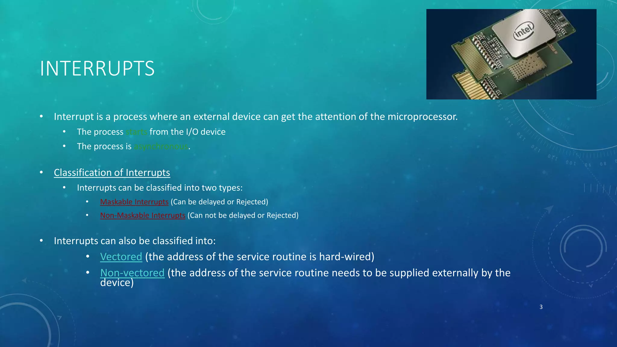
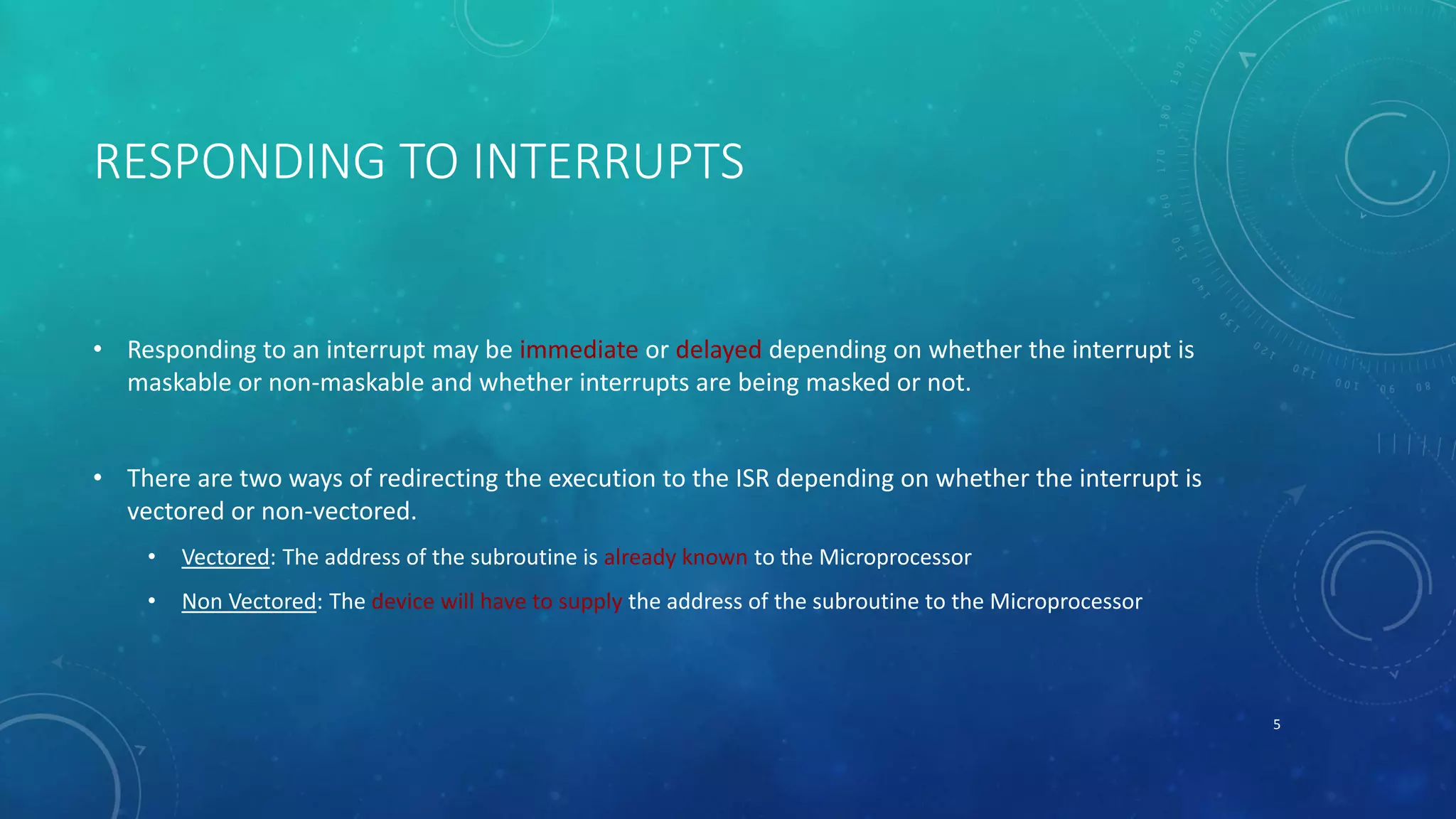
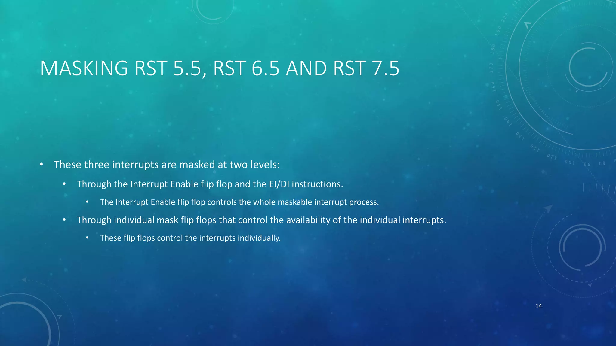
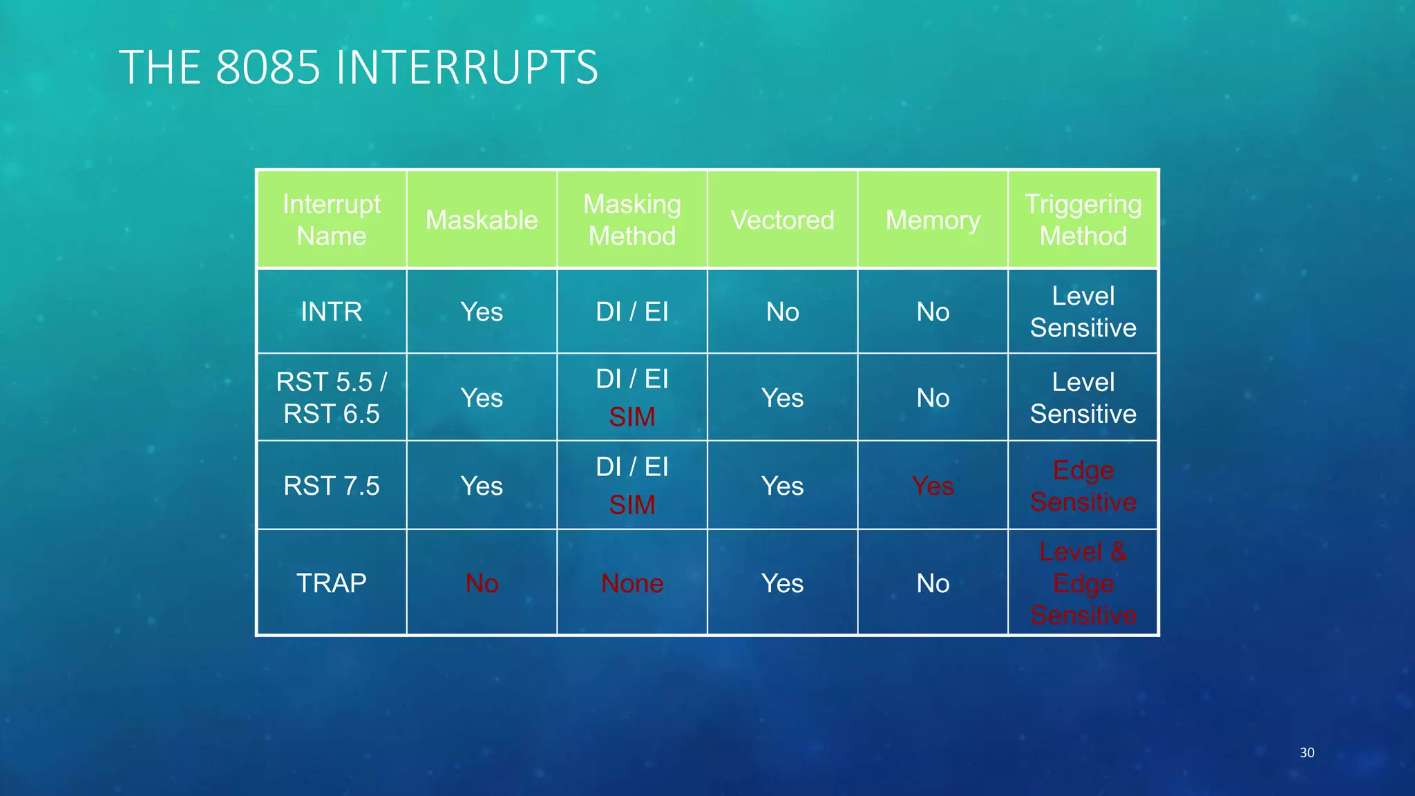
- Classification of interrupts as maskable or non-maskable, vectored or non-vectored.
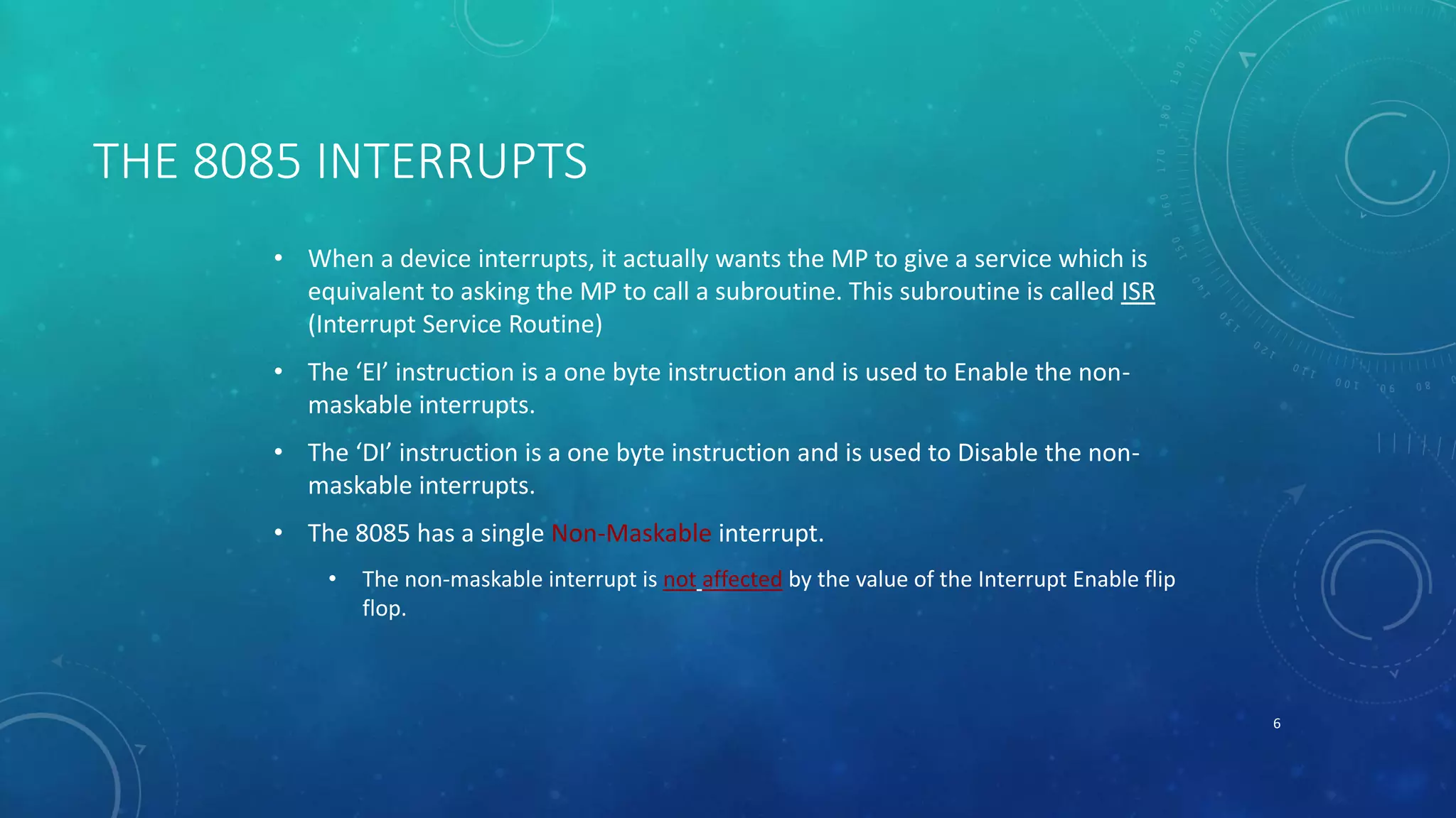
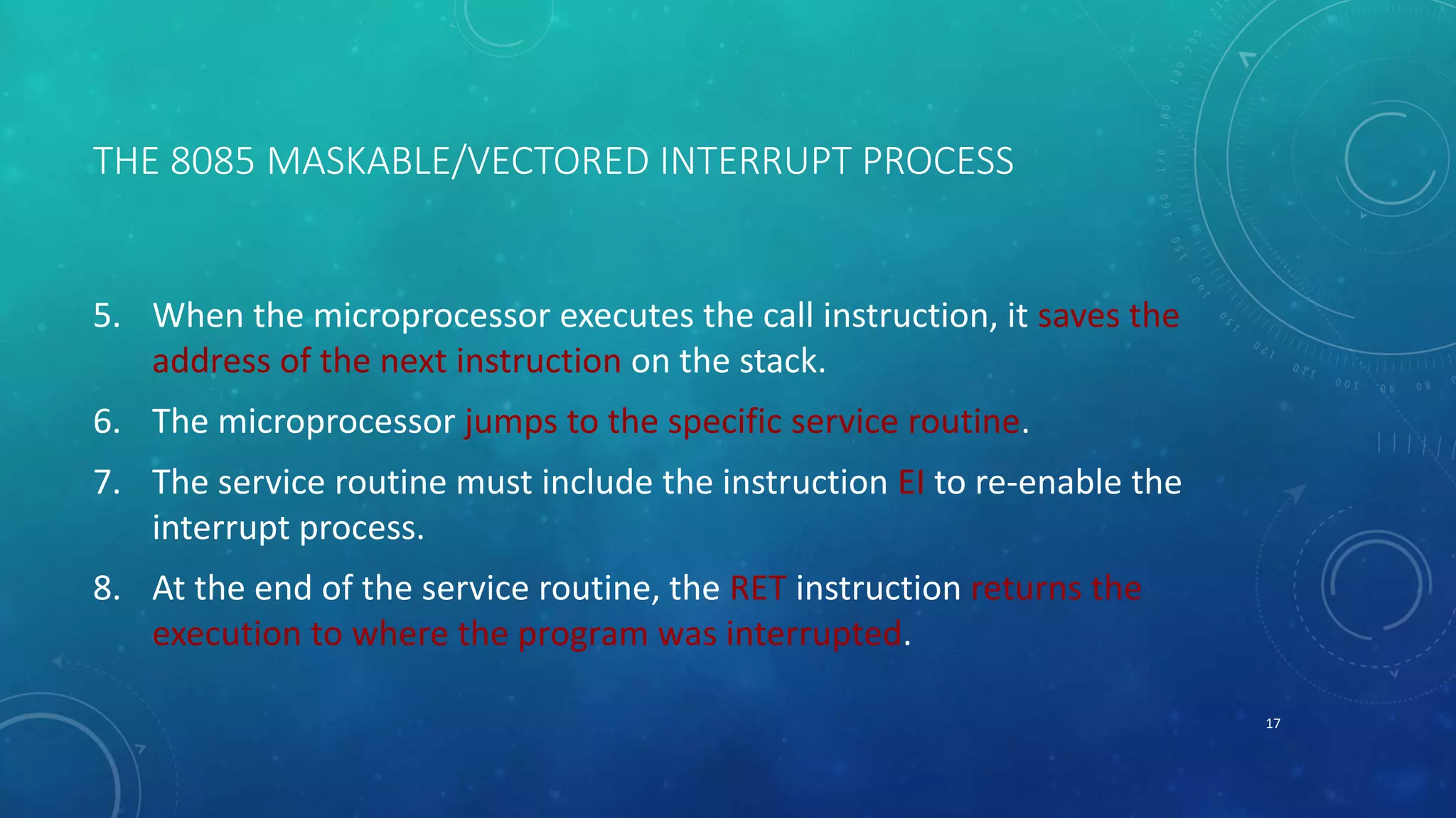
- What happens when a microprocessor is interrupted and how it responds by jumping to an interrupt service routine.
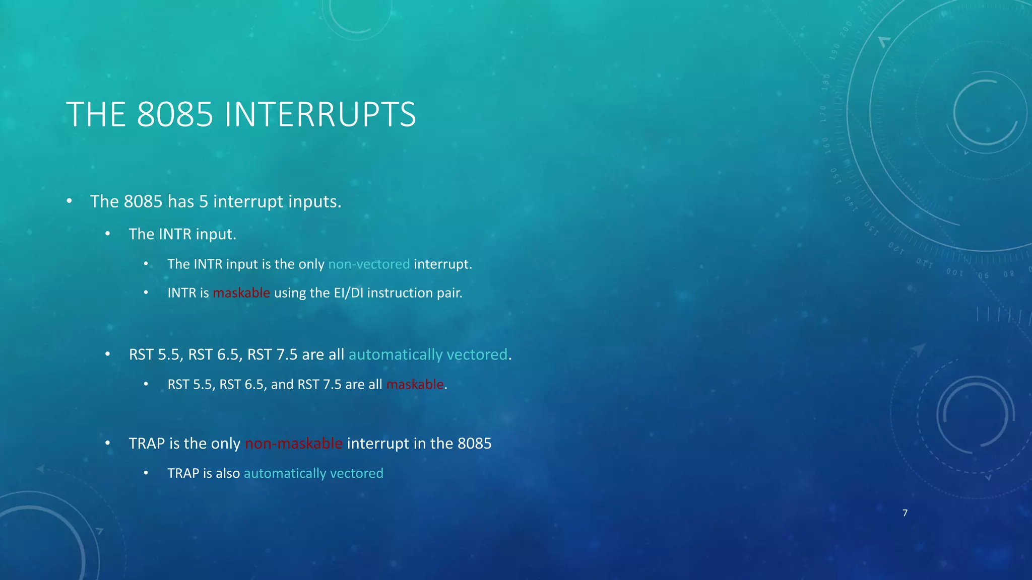
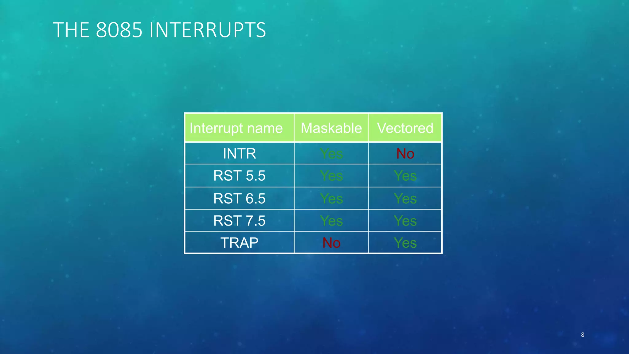
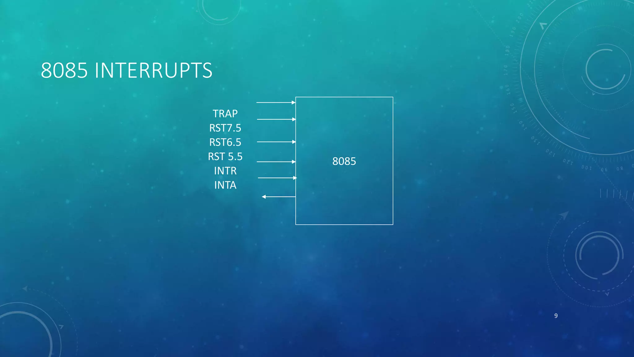
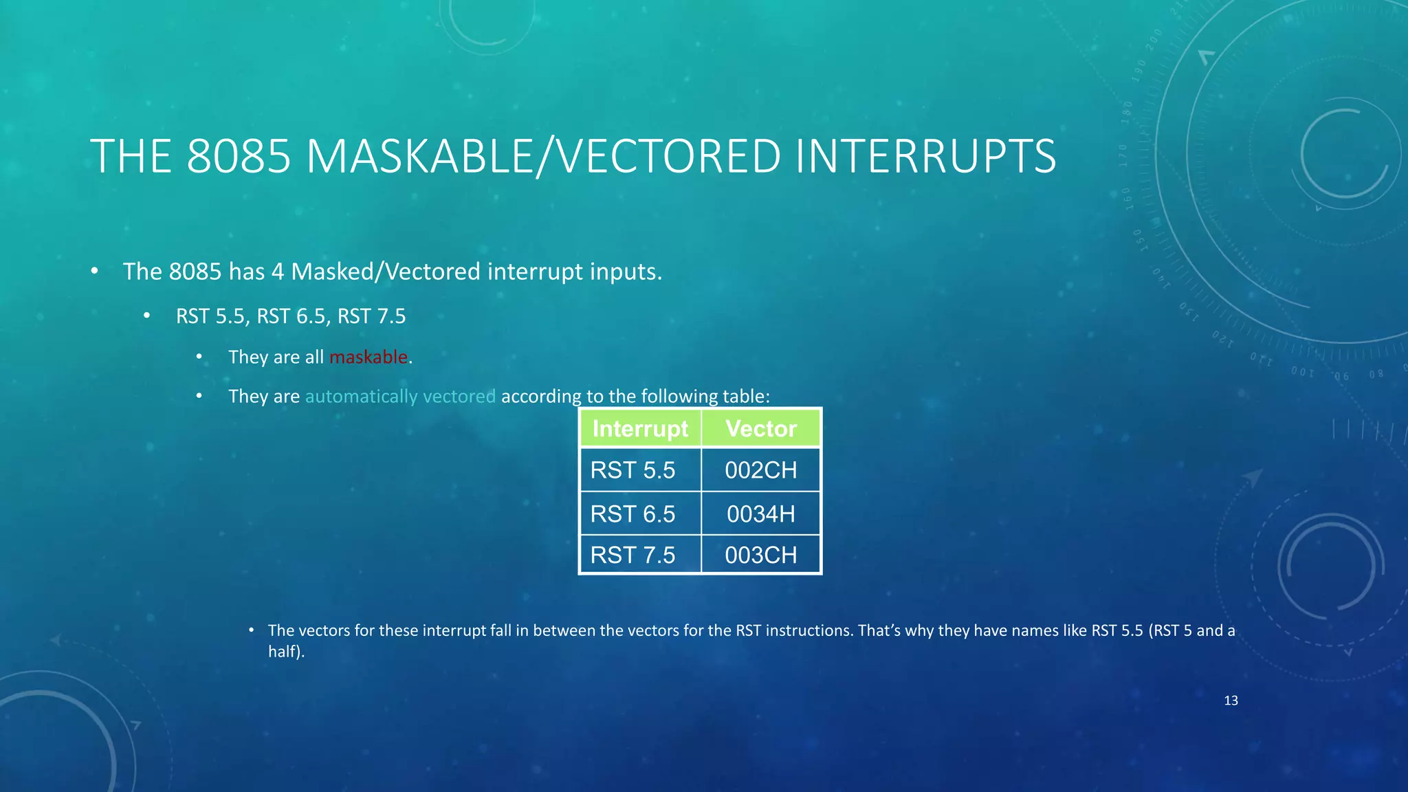
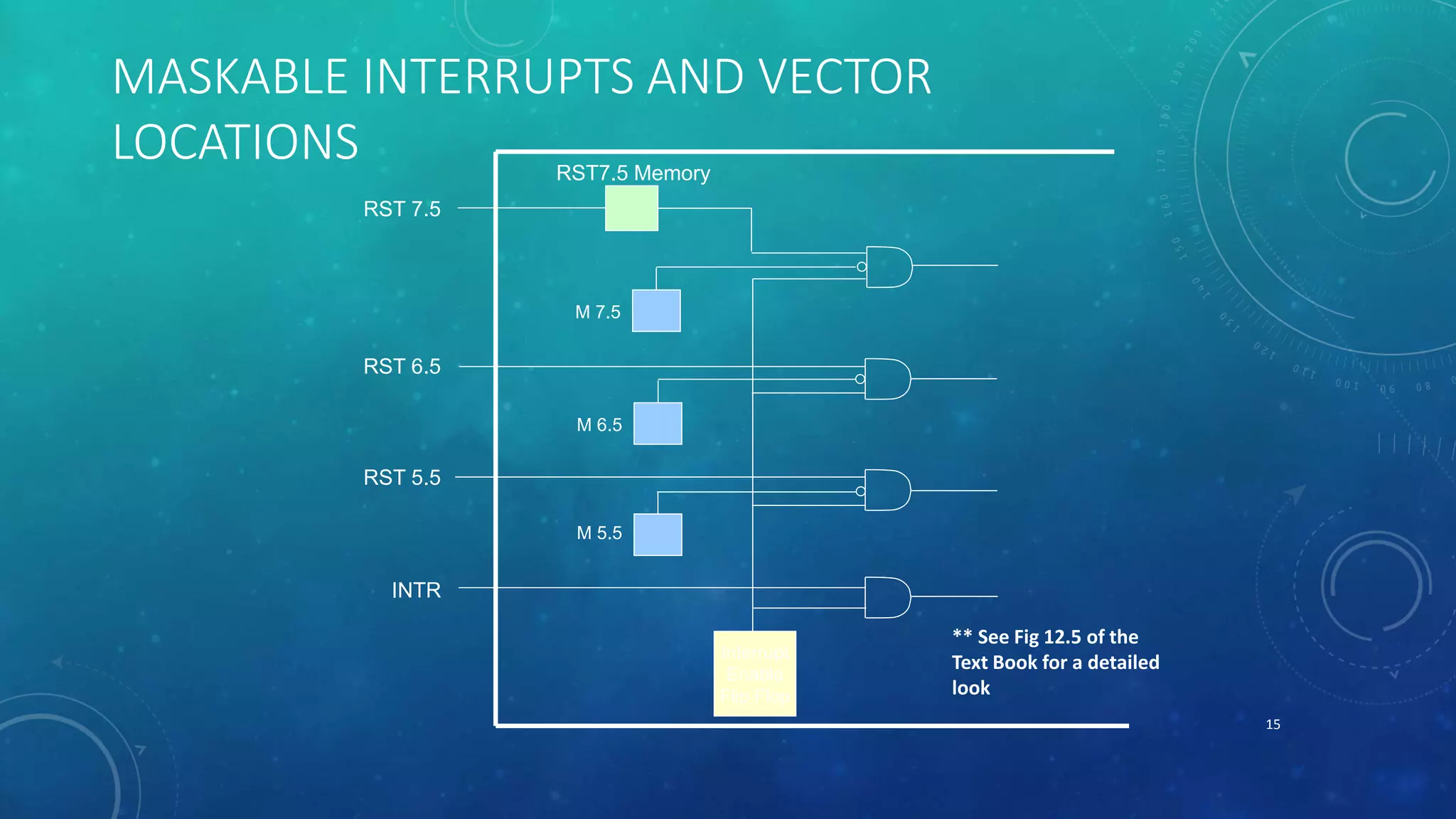
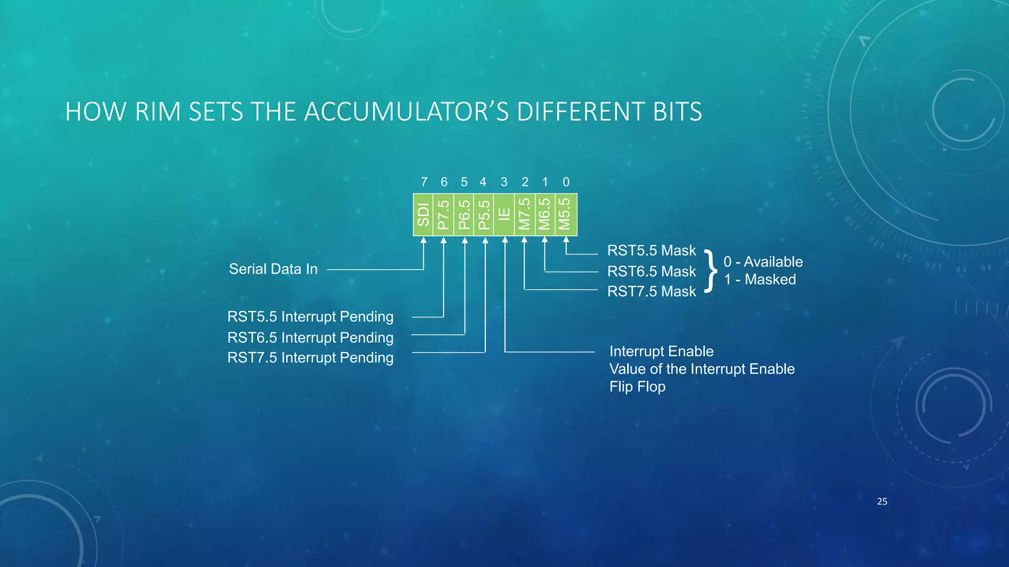
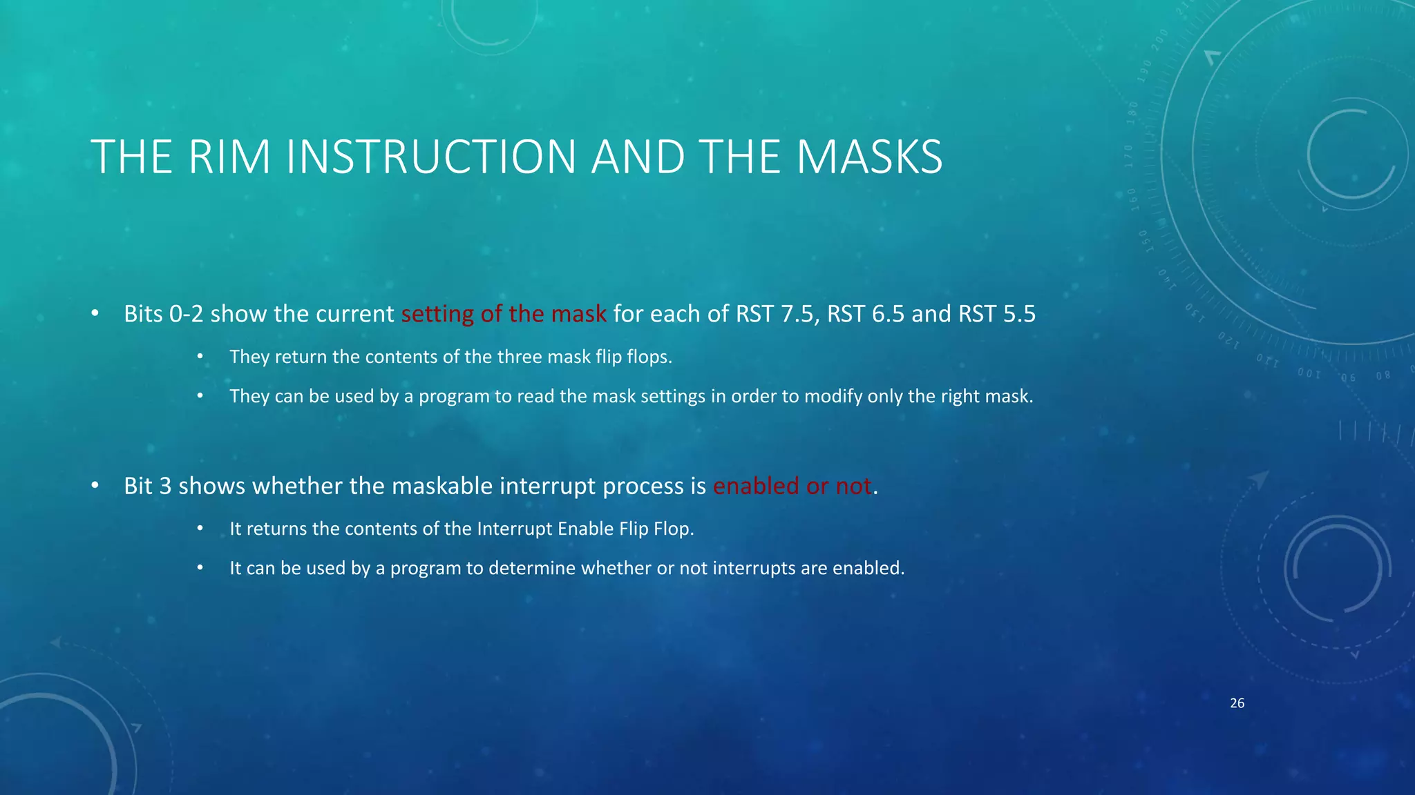
- The different interrupts in the 8085 microprocessor including INTR, RST 5.5, RST 6.5, RST 7.5, and TRAP.
- How to allow multiple devices to interrupt using priorities and a priority encoder.
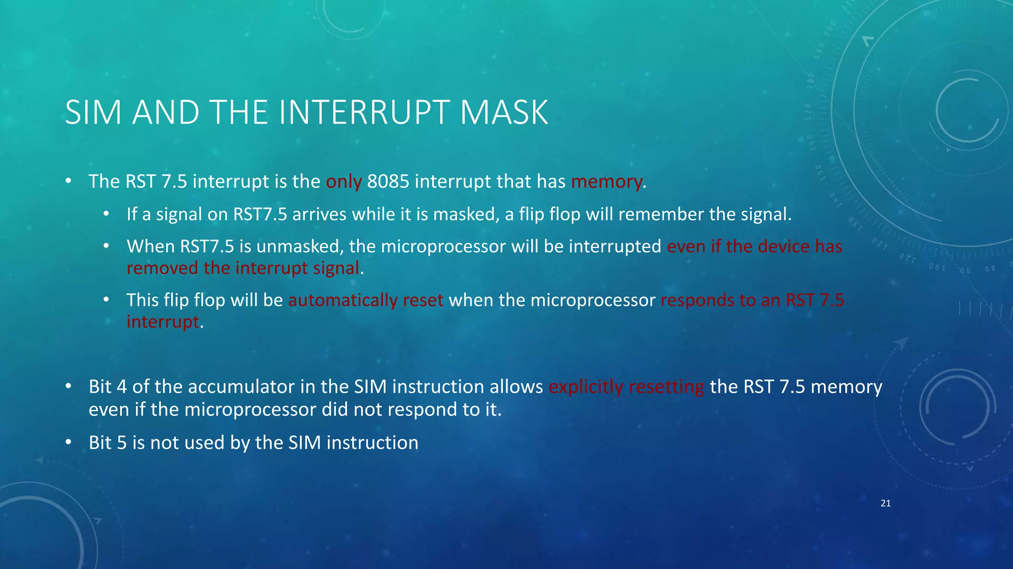
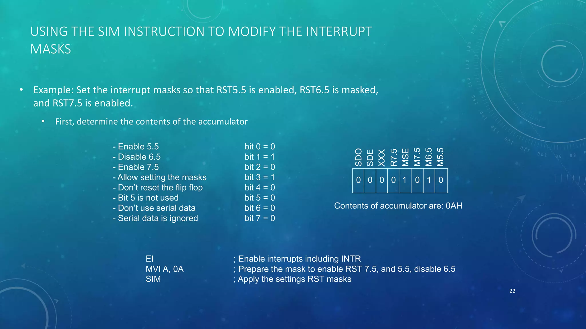
- How the 8085 handles multiple interrupts and priorities between RST 5.5


![Vibe Coding vs. Spec-Driven Development [Free Meetup]](https://cdn.slidesharecdn.com/ss_thumbnails/vibecodingvsspecdrivendevelopment-251209105622-43f455e7-thumbnail.jpg?width=640&height=640&fit=bounds)


