Downloaded 260 times
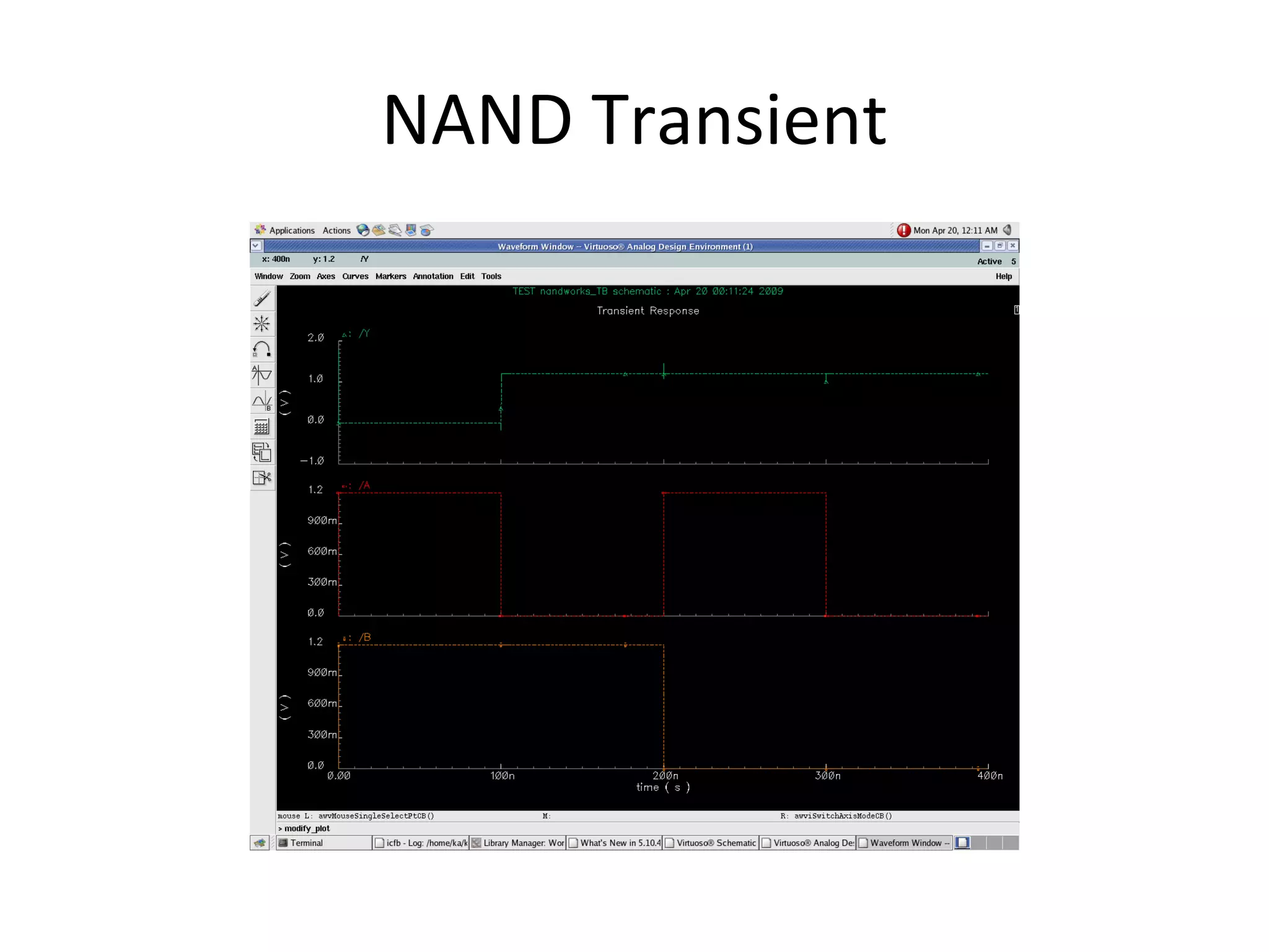

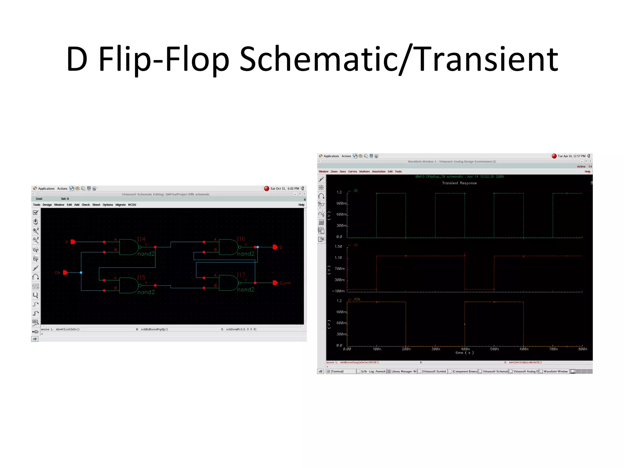
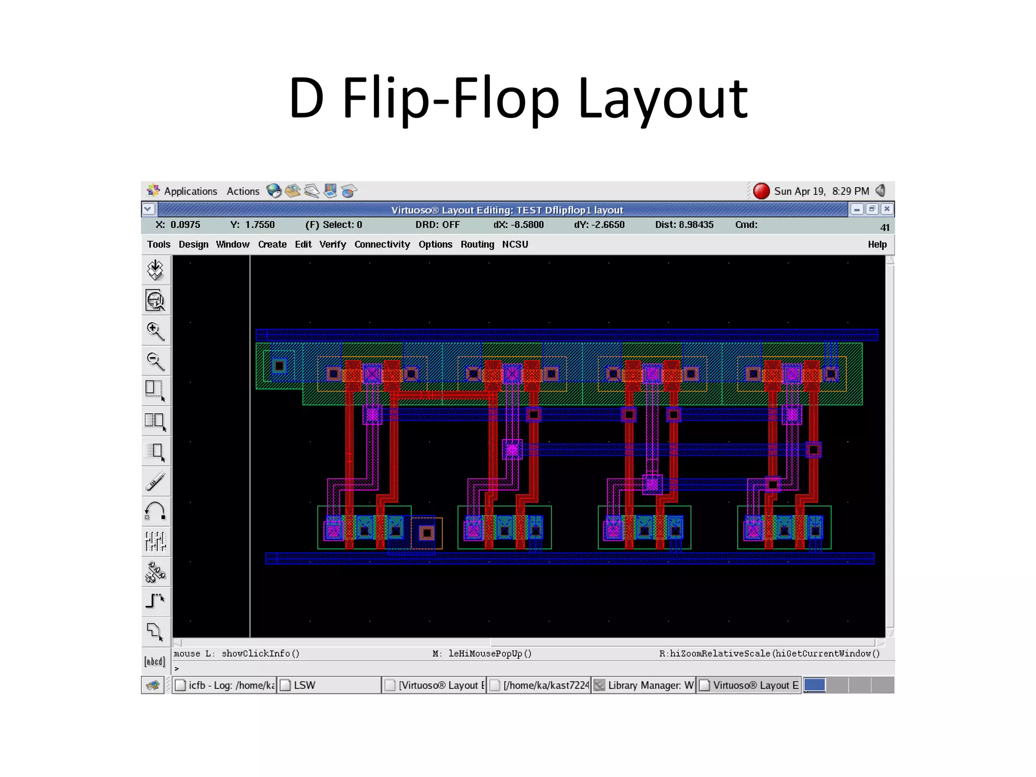

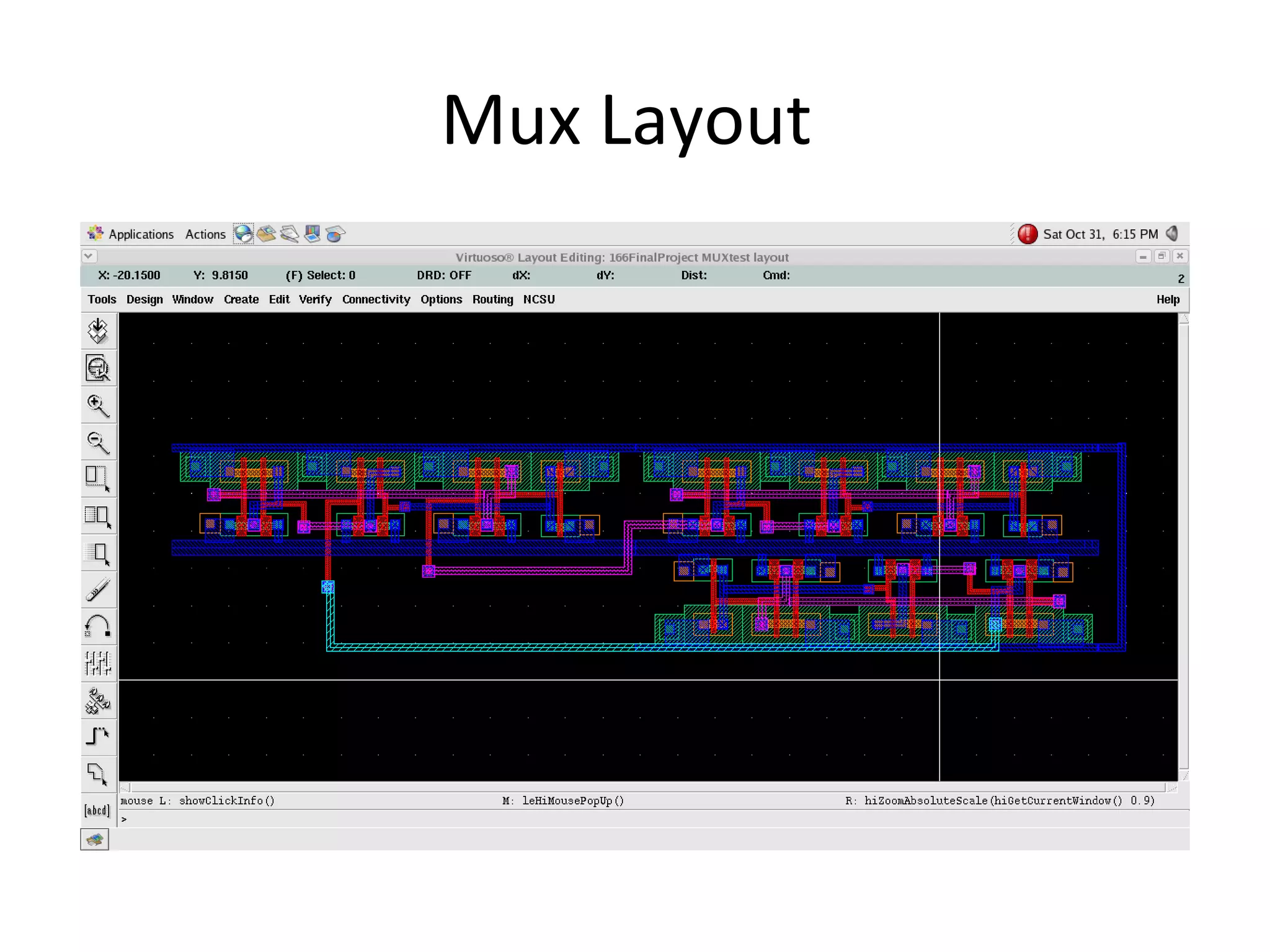
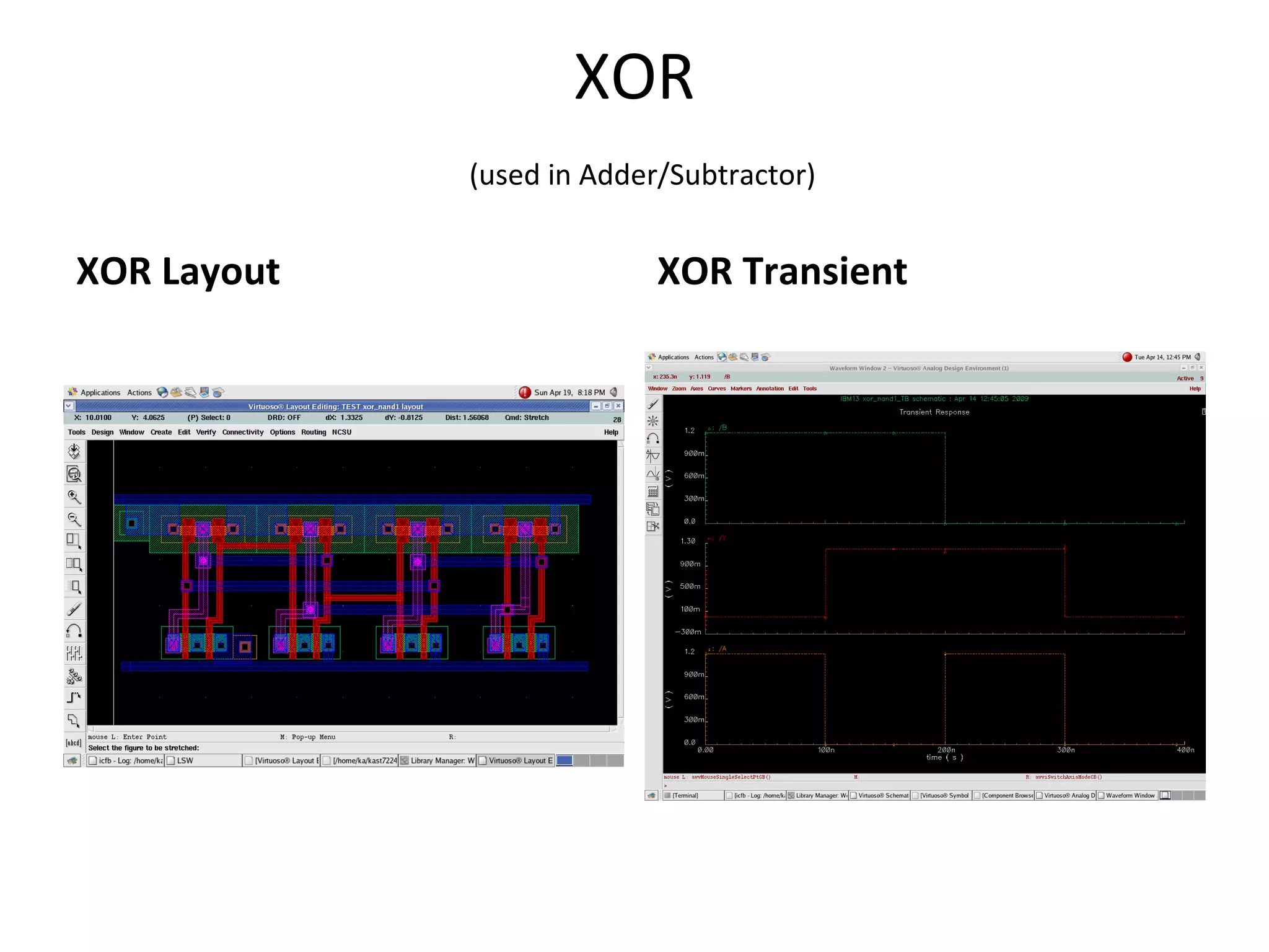

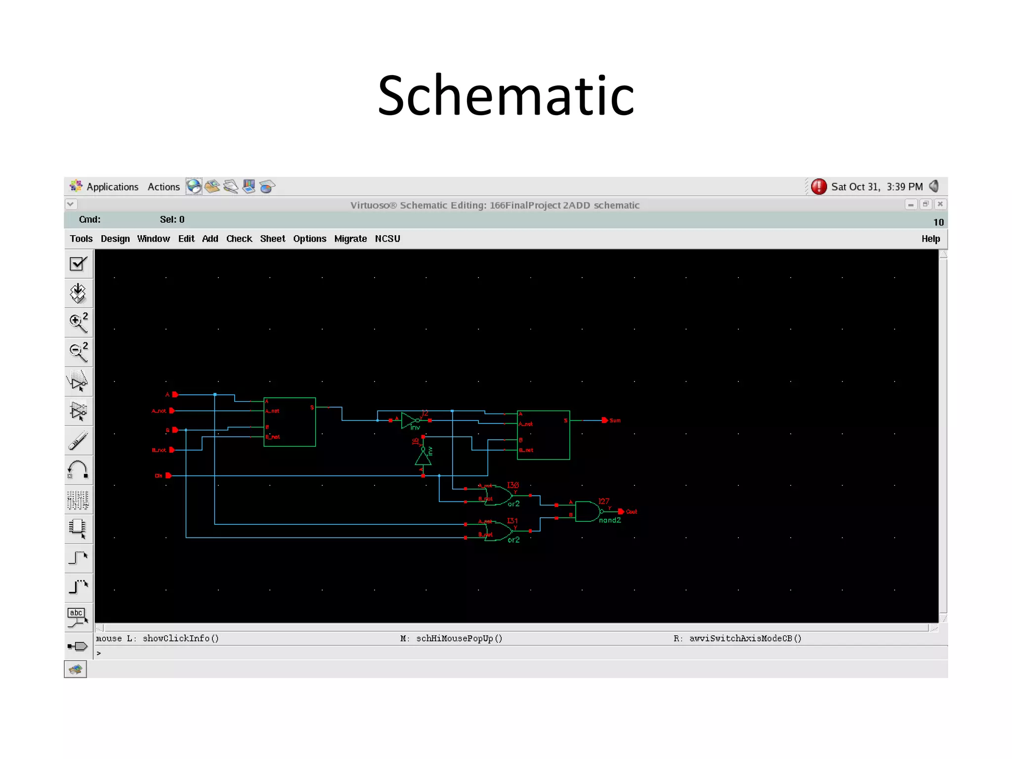
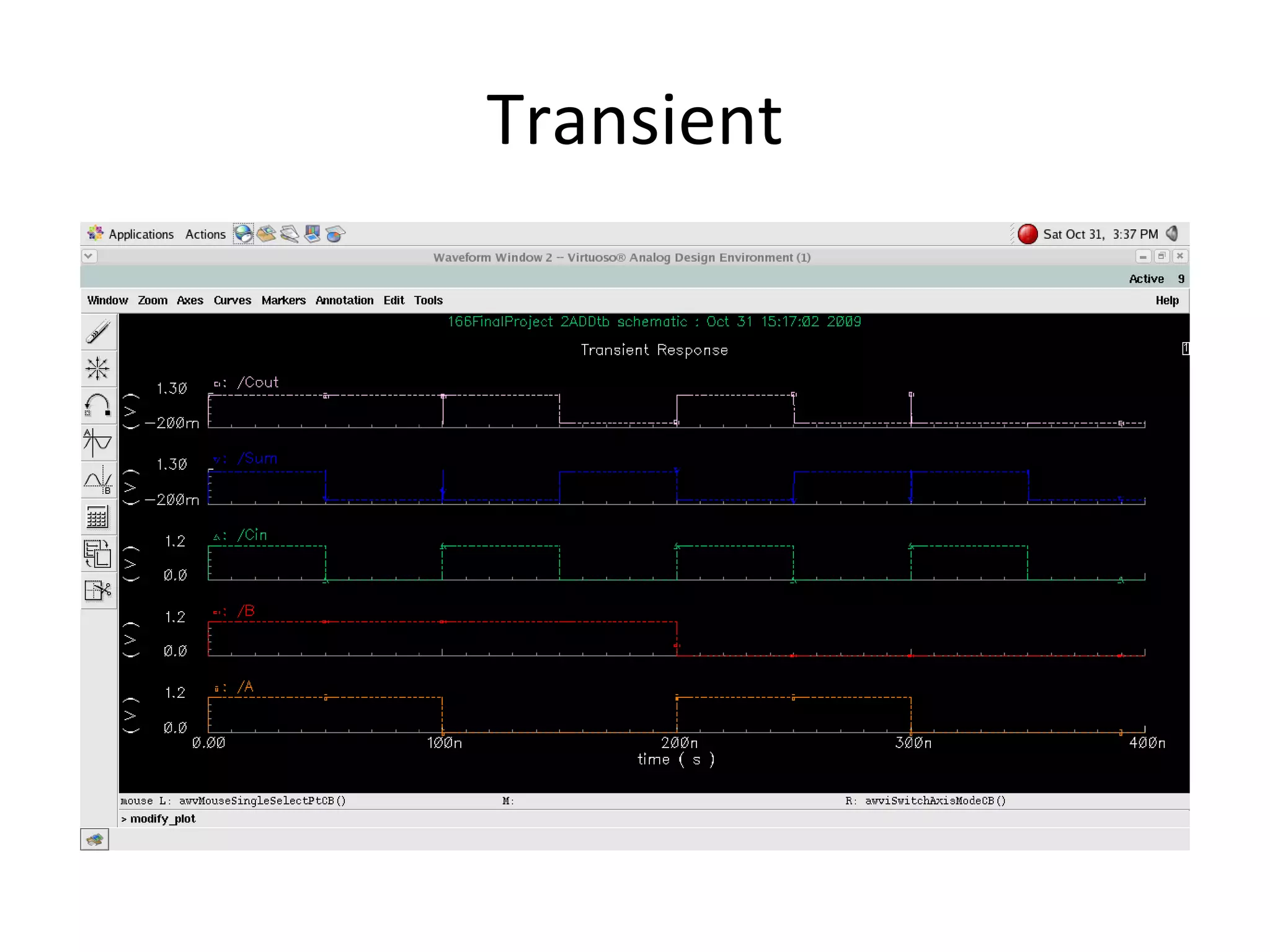
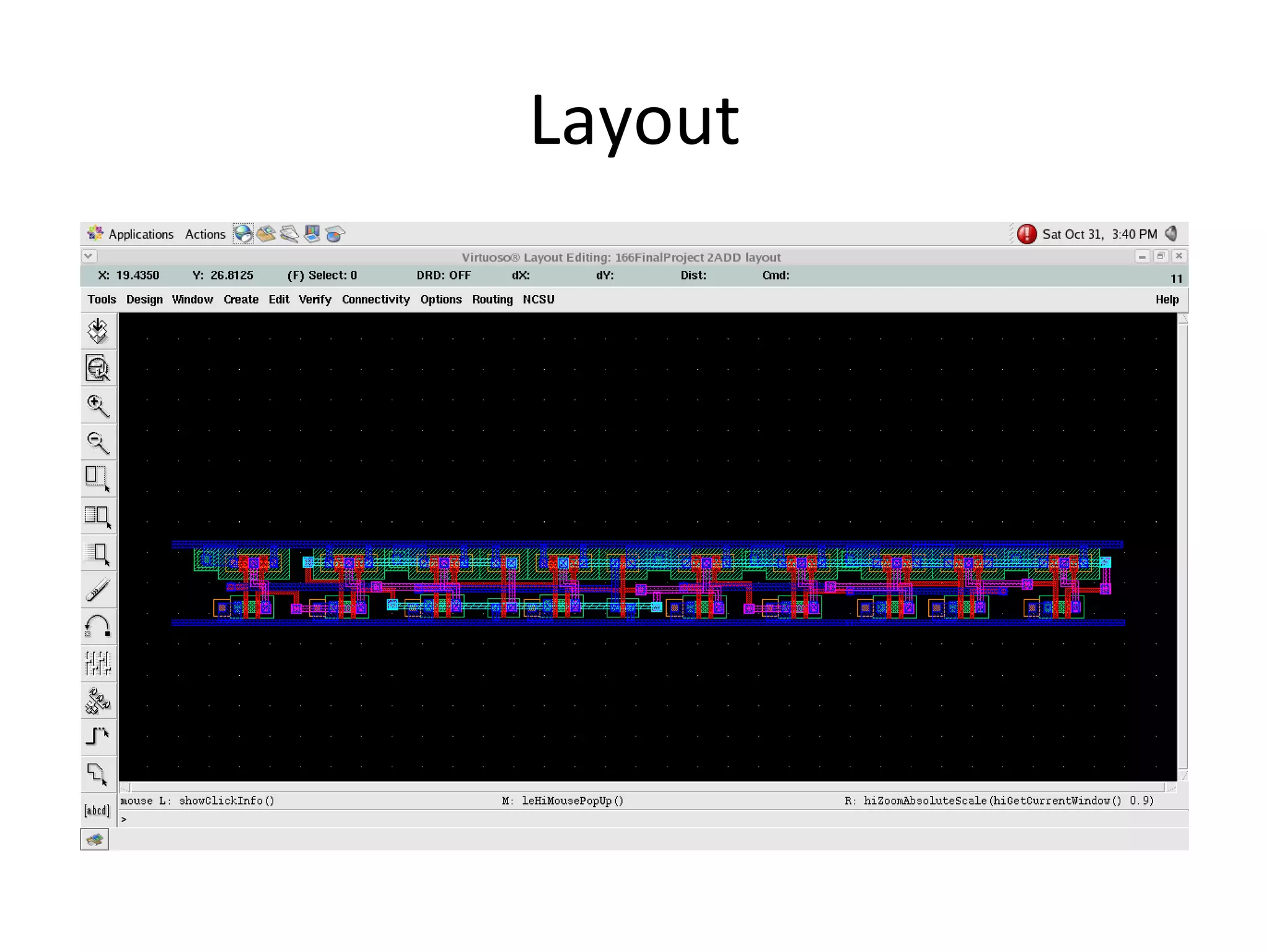
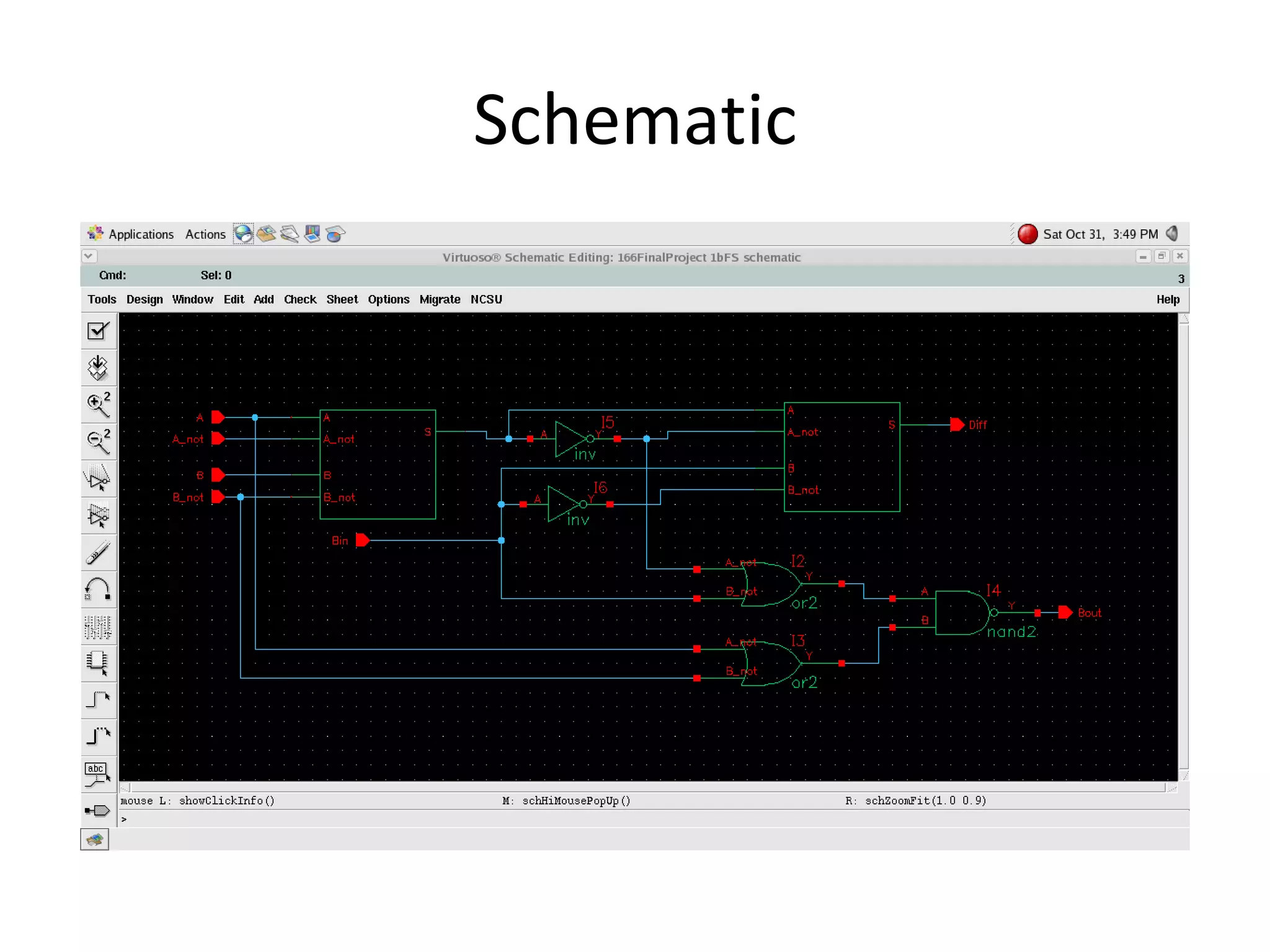
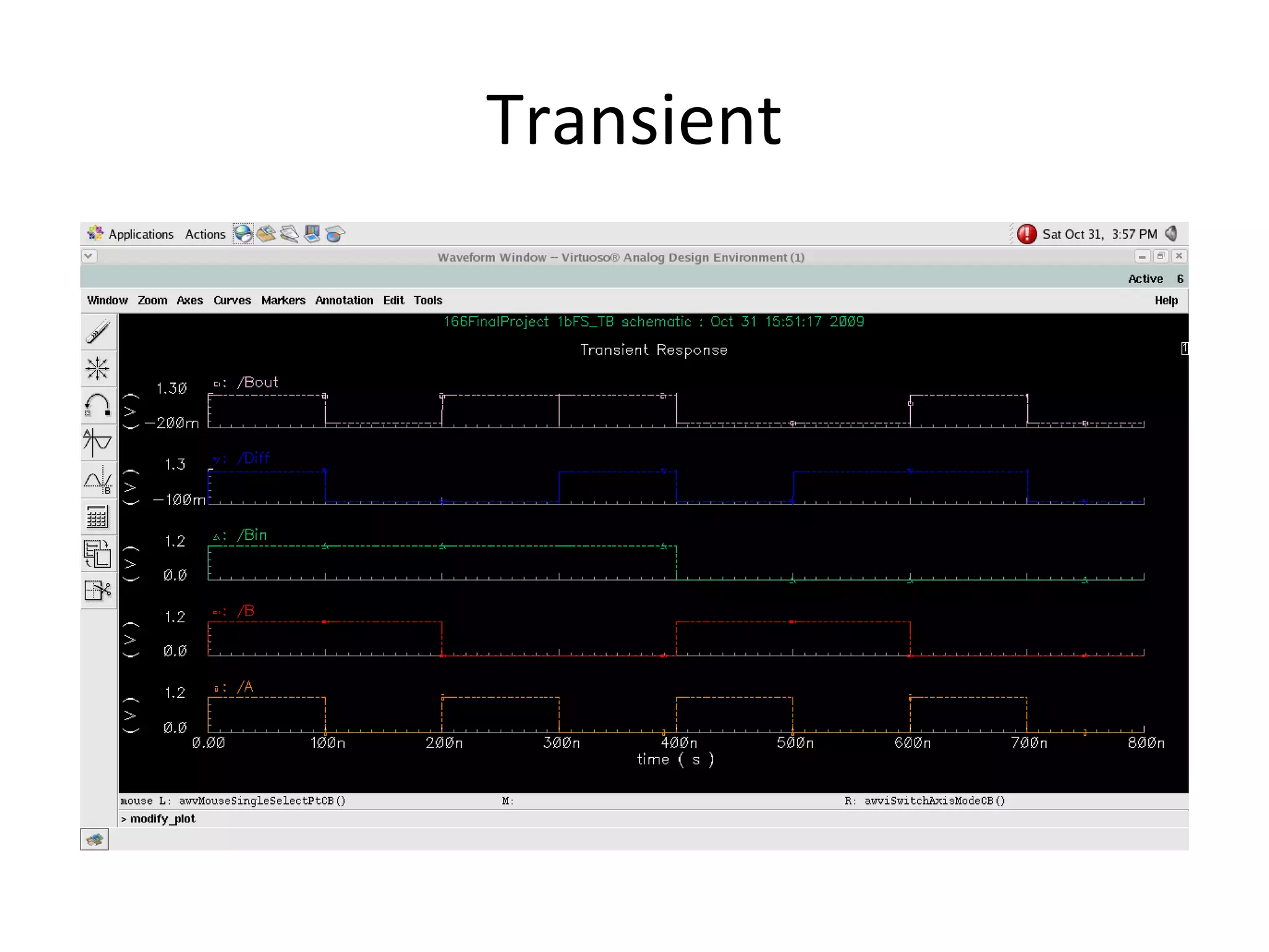
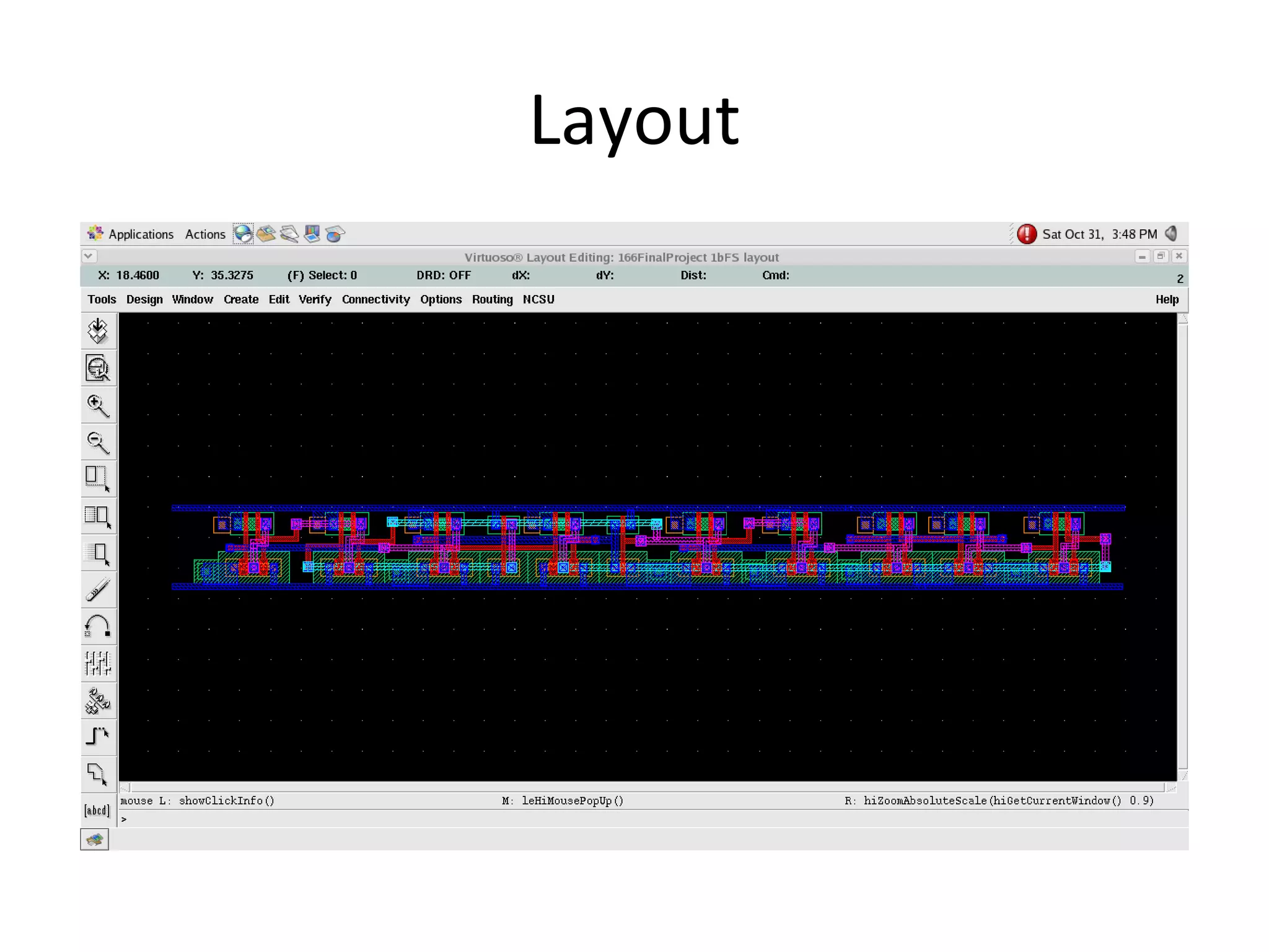
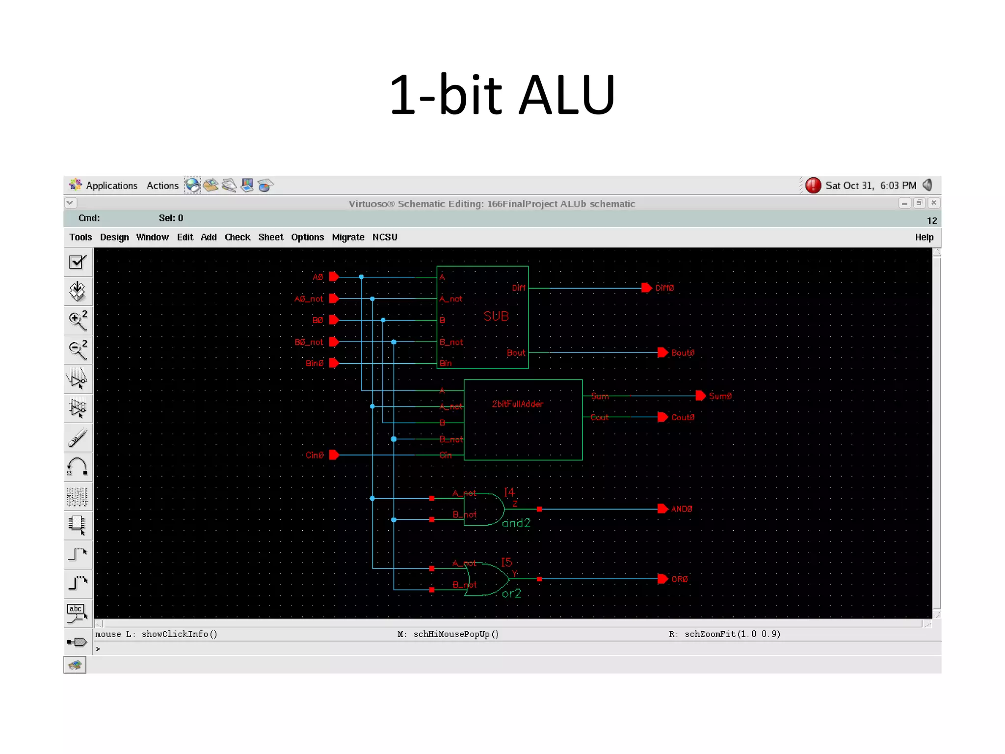
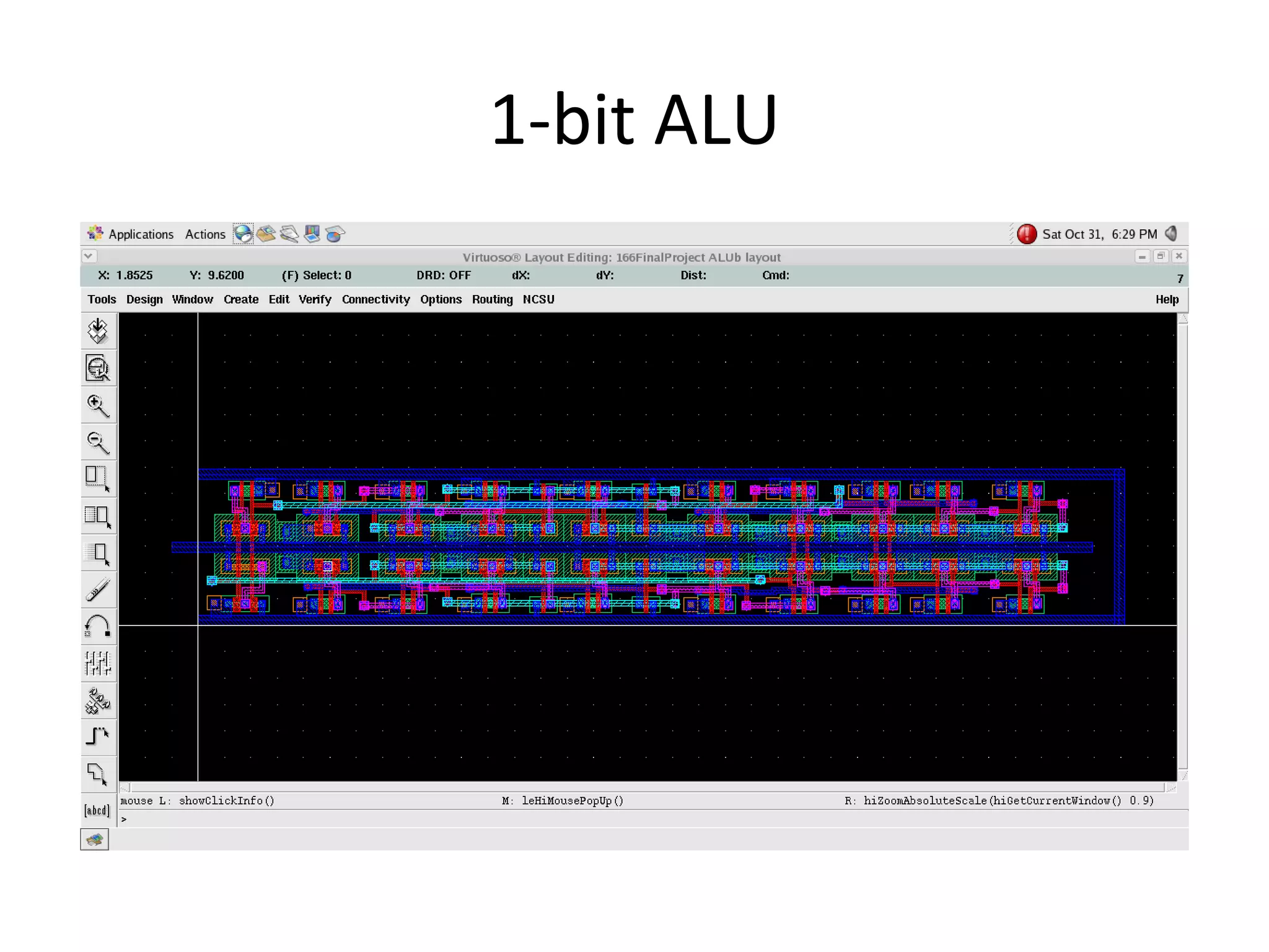
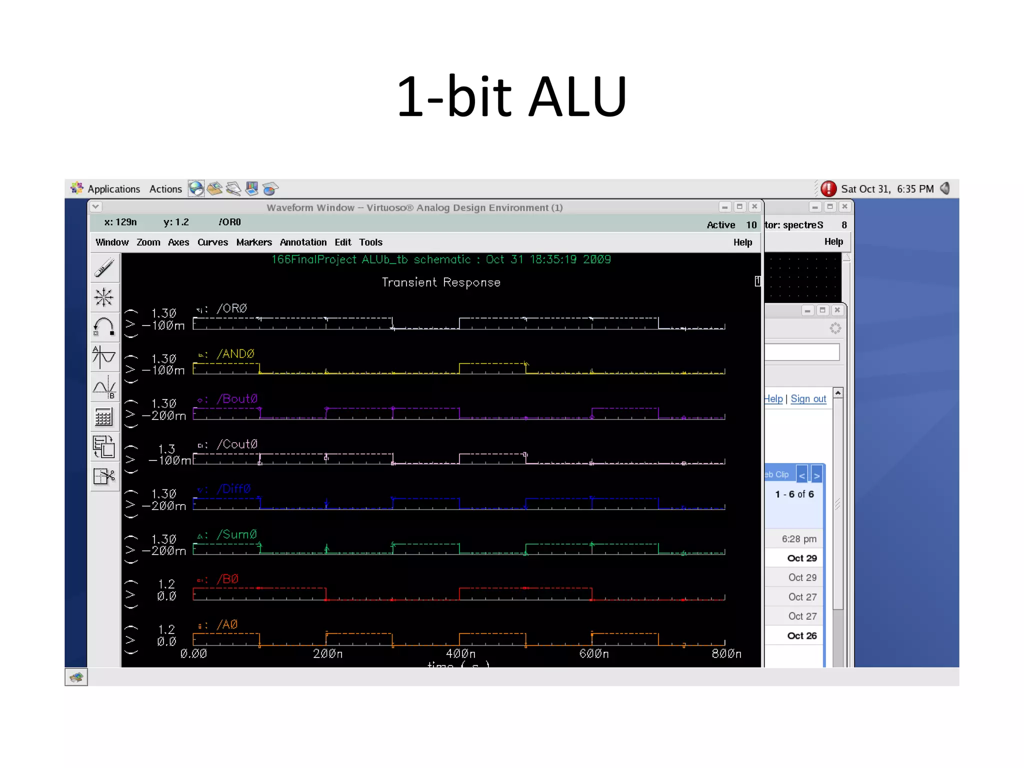
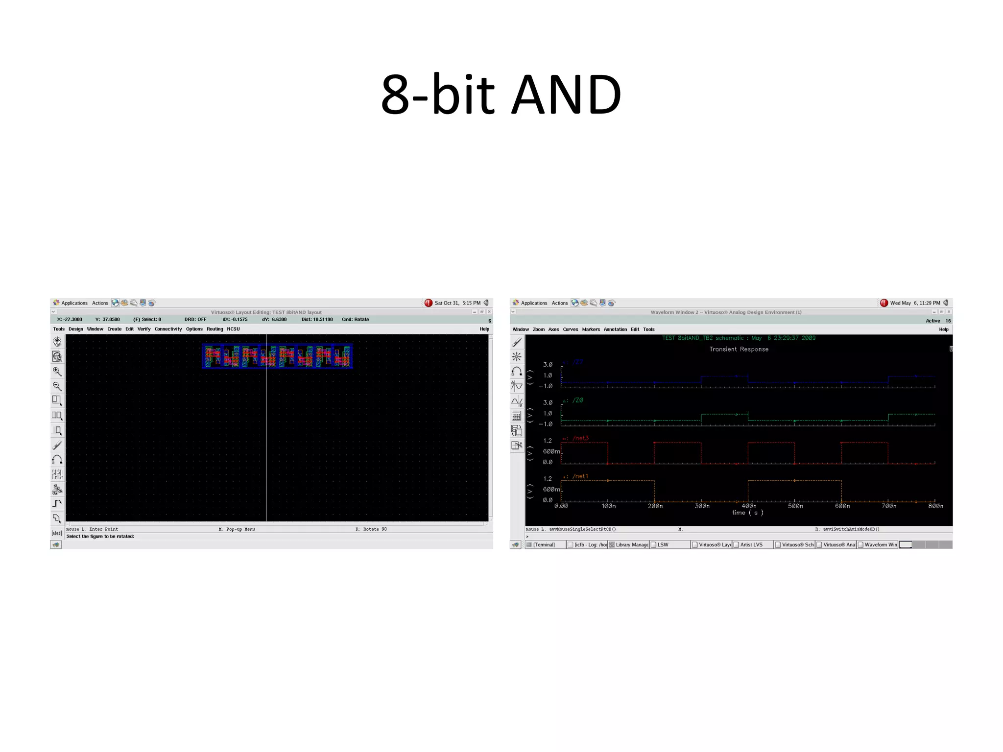
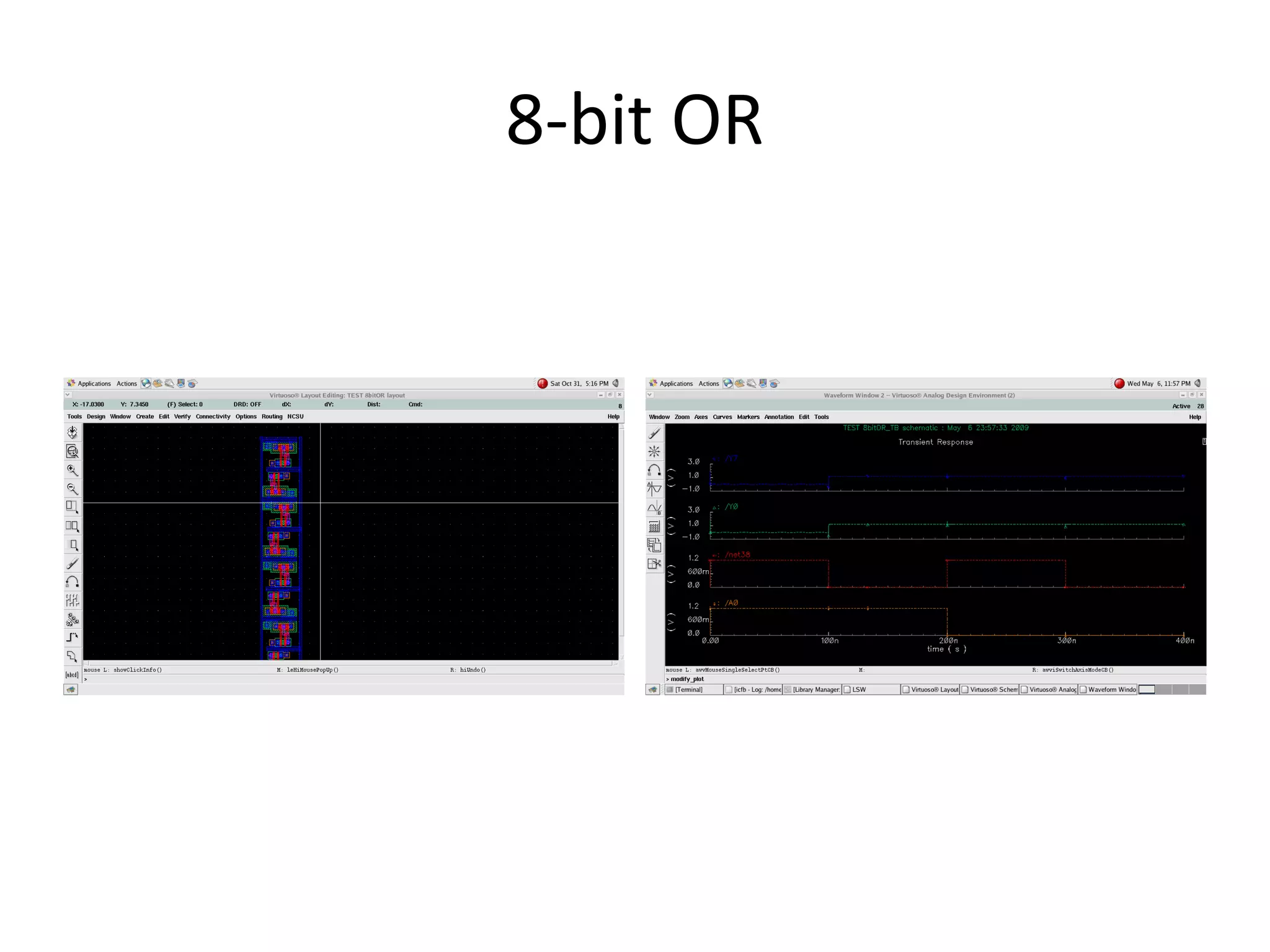
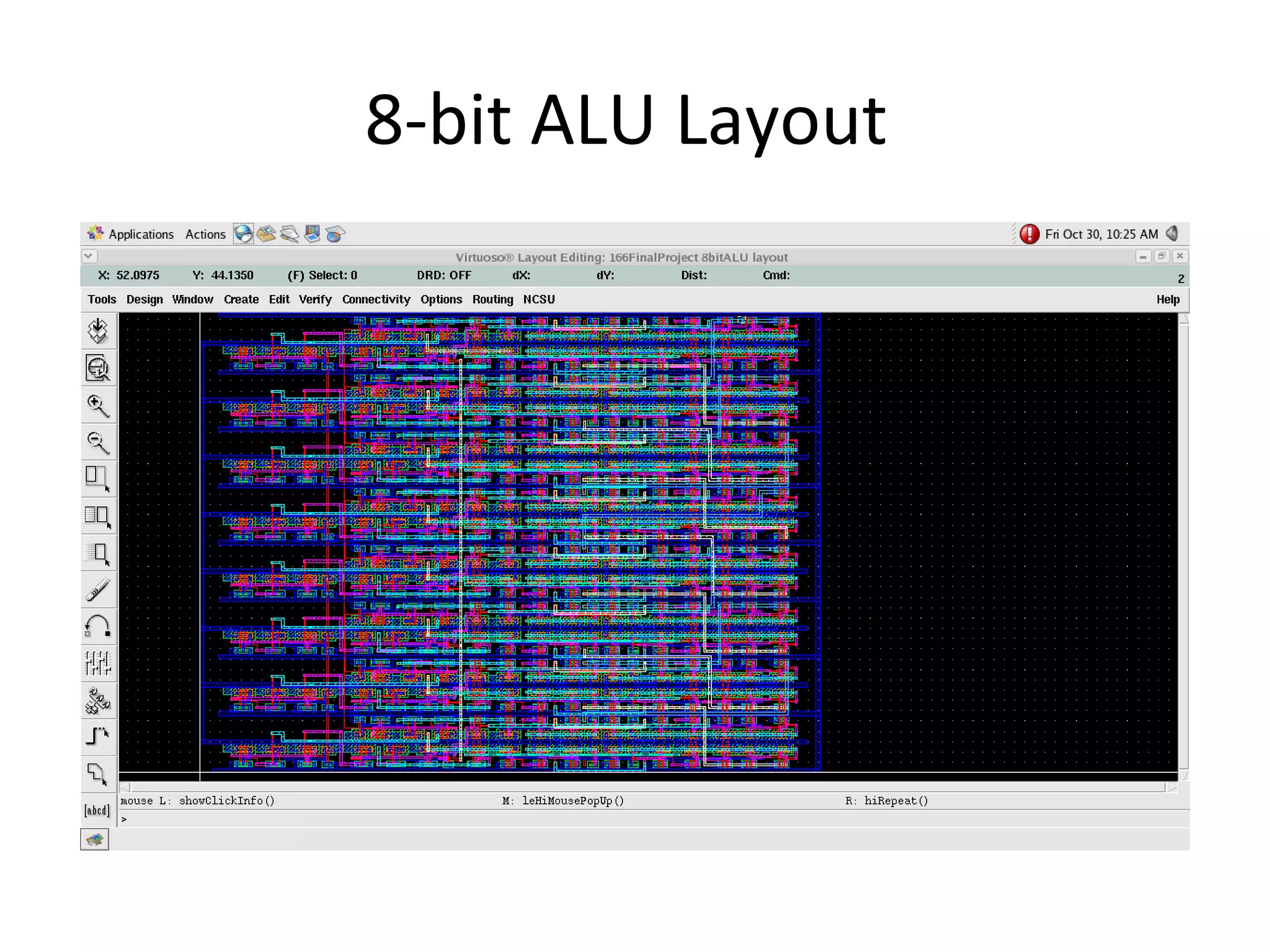

This document outlines the design and implementation of an 8-bit ALU (arithmetic logic unit). Basic logic gates like NOR and NAND were created first. D flip-flops and multiplexers were used to store and select data. An XOR gate, 1-bit full adder, 1-bit full subtractor, and 1-bit ALU were designed and tested. Finally, an 8-bit ALU was implemented and tested for minimum size and maximum speed.