It Defines what is Programmable Logic Array(PLA) also explains it in easy wording with syntax and Example...
It also cover what is Combinational & Sequential Logic Circuit and the Difference b/w these both. :)
The document discusses Programmable Logic Arrays (PLAs) and Programmable Array Logic (PALs). It explains that a PLA is similar to a PROM but does not provide full decoding and generates only some minterms. It has three sets of fuses to program the AND gates, OR gates, and output function. A PAL has a fixed OR array and programmable AND array, making it easier to program but less flexible than a PLA. The differences between PLA and PAL are described, along with an example and implementation details.
- The document discusses magnitude comparators, which are used to compare two binary numbers and output whether the first number is less than, equal to, or greater than the second number.
- It explains 1-bit and 2-bit magnitude comparators, providing their truth tables and logic diagrams. For a 1-bit comparator, it derives the logic expressions for the three outputs using K-maps.
- For a 2-bit comparator, it similarly provides the truth table and derives the K-map expressions for the three outputs. It then shows the full logic diagram for a 2-bit magnitude comparator using AND, OR, and NOT gates.
Programmable logic devices (PLDs) like PLA, PAL, CPLD and FPGA allow implementing logic circuits using programmable switches. PLA and PAL have programmable AND planes and OR planes to implement sum-of-products logic. PALs are simpler than PLAs with fixed OR planes. CPLDs contain multiple PAL-like blocks with programmable interconnects. FPGAs provide programmable logic blocks and interconnects to implement larger circuits without AND/OR planes. All PLDs require programming using CAD tools to set the switches for the desired logic function.
This document discusses parity generators and checkers, which are used to detect errors in digital data transmission. It explains that a parity generator adds an extra parity bit to binary data to make the total number of 1s either even or odd. This allows a parity checker circuit at the receiver to detect errors if the number of 1s is the wrong parity. It provides truth tables and logic diagrams for 3-bit even and odd parity generators and an even parity checker. The boolean expressions for the parity generator and checker circuits are also derived.
This document discusses the architectures and applications of CPLDs and FPGAs. It begins by classifying programmable logic devices and describing simple programmable logic devices like PLDs, PALs, and GALs. It then discusses more complex programmable logic devices like CPLDs, describing their architecture which consists of logic blocks, I/O blocks, and a global interconnect. Finally, it covers field programmable gate arrays including their architecture of configurable logic blocks, I/O blocks, and a programmable interconnect, as well as describing Xilinx's logic cell array architecture for FPGAs.
A combinational circuit is a logic circuit whose output is solely determined by the present input. It has no internal memory and its output depends only on the current inputs. A half adder is a basic combinational circuit that adds two single bits and produces a sum and carry output. A full adder adds three bits and produces a sum and carry like the half adder. Other combinational circuits discussed include half and full subtractors, decoders, encoders, and priority encoders.
This document discusses programmable logic devices (PLDs). It describes the different types of PLDs including SPLDs, CPLDs, and FPGAs. SPLDs are the least complex, while CPLDs have higher capacity than SPLDs and allow for more complex logic circuits. FPGAs have the greatest logic capacity and consist of an array of configurable logic blocks and programmable interconnects. The document also covers how PLDs are programmed using schematic entry or text-based entry along with required programming software and hardware.
Programmable logic devices (PLDs) allow users to implement digital logic designs on a single chip. PLDs have advantages over traditional integrated circuits like lower costs for lower production volumes and shorter design times. Common types of PLDs include simple programmable logic devices like PALs, GALs, and CPLDs. PLDs are configured using memory like SRAM, EPROM, EEPROM, or flash to store the programmed logic pattern. Reprogrammability allows PLDs to be reused for different logic functions.
Complex Programmable Logic Device (CPLD) Architecture and Its Applicationselprocus
A CPLD (complex programmable logic device) chip includes several circuit blocks on a single chip with inside wiring resources to attach the circuit blocks. Each circuit block is comparable to a PLA or a PAL.
This document discusses decoders and encoders. It defines a decoder as a circuit that accepts a binary input and activates only one output corresponding to the input. An encoder is the inverse, converting an active input to a coded output. Various types of decoders and encoders are described, including 2-to-4 decoders, 3-to-8 decoders, priority encoders, decimal-to-BCD encoders, and octal-to-binary encoders. Truth tables and logic diagrams are provided as examples. Expansion of decoders using multiple lower-order decoders is also covered.
1. Programmable Logic Arrays (PLAs) are pre-fabricated logic blocks containing AND and OR gates that can be personalized by making or breaking connections between gates. This allows them to implement general purpose logic functions.
2. An example shows a 3x2 PLA implementing 4 logic functions through a personality matrix that defines which inputs are connected to each product term and which product terms are connected to each output.
3. PALs (Programmable Array Logic) are similar to PLAs but contain a fixed OR array, limiting them to functions with at most 4 products.
The 8051 microcontroller has 40 pins that provide input/output capabilities. It has four 8-bit I/O ports (P0, P1, P2, P3) that allow connection to external devices. Unlike microprocessors, the 8051 has onboard I/O ports so no additional chips are needed. The I/O ports use circuits that allow pins to be individually configured as inputs or outputs using latches controlled by the microcontroller.
VLSI subsystem design processes and illustrationVishal kakade
This document discusses the design processes for digital subsystem design. It begins by outlining the objectives of design consideration, problem and solution, basic digital processor structure, and datapath. It then discusses general considerations for subsystem design such as lower unit cost and higher reliability. It presents some common problems in design like how to design complex systems efficiently. It proposes solutions like top-down design and partitioning the system. The document then illustrates the design processes through examples like designing a 4-bit shifter and ALU subsystem. It provides block diagrams, logic diagrams and layouts at different stages of the design process.
This document discusses programmable logic devices (PLDs), including their basic components and types. PLDs are integrated circuits that can be configured by the user to perform different logic functions. They contain programmable AND and OR gates that allow the user to define the logic function by programming the connections between the gates. Common types of PLDs include PROM, PAL, and PLA, which differ in whether their AND gates and/or OR gates are programmable. The document provides examples and diagrams to illustrate how basic logic functions can be implemented using each type of PLD.
An arithmetic logic unit (ALU) is a digital electronic circuit that performs arithmetic and bitwise logical operations on integer binary numbers.
This is in contrast to a floating-point unit (FPU), which operates on floating point numbers. It is a fundamental building block of many types of computing circuits, including the central processing unit (CPU) of computers, FPUs, and graphics processing units.
A single CPU, FPU or GPU may contain multiple ALUs
History Of ALU:Mathematician John von Neumann proposed the ALU concept in 1945 in a report on the foundations for a new computer called the EDVAC(Electronic Discrete Variable Automatic Computer
Typical Schematic Symbol of an ALU:A and B: the inputs to the ALU
R: Output or Result
F: Code or Instruction from the
Control Unit
D: Output status; it indicates cases
Circuit operation:An ALU is a combinational logic circuit
Its outputs will change asynchronously in response to input changes
The external circuitry connected to the ALU is responsible for ensuring the stability of ALU input signals throughout the operation
This document discusses programmable logic arrays (PLAs) and provides examples of implementing logic functions using a PLA. It defines a PLA as having programmable AND gates followed by programmable OR gates, making it well-suited for implementing sums-of-products logic functions. The document includes the structure of a PLA, the procedure for implementation, and provides four examples showing the logic diagrams and programming tables for PLAs implementing different logic functions with various numbers of inputs, outputs, and product terms.
This presentation gives an overview of FPGA devices. An FPGA is a device that contains a matrix of re-configurable gate array logic circuitry. When a FPGA is configured, the internal circuitry is connected in a way that creates a hardware implementation of the software application.
FPGA devices can deliver the performance and reliability of dedicated hardware circuitry.
This presentation discusses the Serial Communication features in 8051, the support for UART. It also discusses serial vs parallel communication, simplex, duplex and full-duplex modes, MAX232, RS232 standards
The document describes the 8051 microcontroller, its features which include 4 I/O ports, 2 timers, serial communication interface, and interrupts. It discusses the internal architecture such as memory organization, registers, and oscillator circuit. The document also provides details on the ports, timers, serial communication, and power modes of the 8051 microcontroller.
This document describes a 4-bit synchronous binary counter. It contains the truth table for a JK flip-flop, diagrams of the counter circuit using 4 JK flip-flops connected in series with a common clock, and tables showing the output logic states and timing diagram as the counter counts from 0 to 15 over 16 clock pulses.
The document discusses the architecture and programming of CPLDs and FPGAs. CPLDs and FPGAs are types of programmable logic devices (PLDs) that can implement complex digital logic functions. CPLDs contain logic blocks that can be programmed, while FPGAs contain an array of configurable logic blocks and interconnects. The document describes the components and programming of PLDs like PLA and PAL, as well as the logic cells and interconnects that make up CPLDs and FPGAs.
This document discusses programmable logic arrays (PLAs). It defines a PLA as a type of programmable logic device that can be used to implement combinational logic circuits. Specifically, a PLA has programmable AND gates linked to a set of programmable OR gates, allowing it to represent large numbers of logic functions. However, PLAs also have disadvantages in that they lack portability and do not provide full decoding of variables or generate all minterms. The document provides an example of logic functions F1 and F2 that could be implemented with a PLA.
This document discusses the architecture of CPLDs and FPGAs. CPLDs consist of PAL-like blocks, I/O blocks, and a programmable interconnect structure. FPGAs consist of an array of configurable logic blocks, I/O blocks, and programmable row and column interconnect channels. The document compares CPLDs and FPGAs, noting that FPGAs have a more complex architecture and unpredictable delays while CPLDs are less complex, cheaper, and have more predictable delays. The conclusion restates that the document discussed the architecture of CPLDs and FPGAs and listed their comparisons.
Designing of 8 BIT Arithmetic and Logical Unit and implementing on Xilinx Ver...Rahul Borthakur
The main objective of this project was to design and verify different operations of Arithmetic and Logical Unit (ALU). To implement ALU, the coding was written in VHDL (VHSIC Hardware Description Language) and verified in ModelSim. The device was configured and using FPGA (Field-programmable gate array) verification, debugging was done.
This document discusses latches and flip flops, which are types of sequential logic circuits. It describes the basic components and functioning of latches like SR latches, D latches, and gated latches. For flip flops, it covers SR flip flops, D flip flops, JK flip flops, and master-slave flip flops. The key differences between latches and flip flops are that latches do not have a clock input while flip flops are edge-triggered by a clock signal. Latches and flip flops are used as basic storage elements in more complex sequential circuits and in computer components like registers and RAM.
Bt0068 computer organization and architecture Techglyphs
The document discusses several topics related to computer organization and architecture. It begins by providing examples of converting decimal numbers to binary. It then explains one stage of logic circuits using AND, OR, XOR, and complement gates. It describes the Von Neumann architecture, including its five classical components and the concept of the Von Neumann bottleneck. Finally, it discusses the register organization of several microprocessors including the 8085, Z8000, and MC68000, comparing their register sets, address buses, and data buses.
The document discusses digital circuits including combinational and sequential circuits. It describes various combinational logic circuits such as half adders, full adders, comparators, multiplexers, encoders, decoders. It also discusses sequential circuits and how they employ memory elements. Arithmetic circuits, binary adders, subtractors, and BCD to 7-segment decoders are explained in detail through diagrams and examples.
This document provides an introduction to arithmetic logic units (ALUs), combinational circuits, and sequential circuits. It defines what an ALU is, its basic components and that it is the fundamental unit of any computing system. It then describes the differences between combinational and sequential circuits, listing examples of each type including common gates, adders and flip-flops. The document outlines the procedures for designing, analyzing and implementing both types of digital circuits.
VLSI design involves integrating hundreds of thousands of transistors onto a single microchip. It follows Moore's law, which predicts that the number of transistors per chip doubles every 18 months. The VLSI design flow includes behavioral, structural, and dataflow modeling using Verilog HDL. Test benches are used to apply inputs to designs and verify functionality. Common digital designs include microprocessors, UARTs for serial communication, and finite state machines like Mealy and Moore machines.
This document discusses the programming technologies and interconnect architectures used in different FPGA devices. It covers antifuse-based OTP technologies used in Actel FPGAs, SRAM-based reprogrammable technologies used in Xilinx FPGAs, and EPROM/EEPROM technologies used in Altera CPLDs. It also describes the segmented channel routing interconnect architecture used in Actel FPGAs and the LCA architecture used in Xilinx FPGAs.
1) The document presents designs for reversible logic gates and their applications in low power circuits. It proposes an improved design for a reversible programmable logic array (RPLA) using multiplexer and Feynman gates that is more efficient than existing designs.
2) It also proposes a method for structuring a reversible arithmetic logic unit (ALU) using reversible logic gates instead of traditional gates, achieving the same functionality with reduced information loss.
3) The RPLA design is demonstrated by implementing reversible 1-bit full adders and subtractors. Simulation results show the proposed design optimizes the number of reversible gates used.
MODELLING AND SIMULATION OF 128-BIT CROSSBAR SWITCH FOR NETWORK -ONCHIPVLSICS Design
This is widely accepted that Network-on-Chip represents a promising solution for forthcoming complex embedded systems. The current SoC Solutions are built from heterogeneous hardware and Software components integrated around a complex communication infrastructure. The crossbar is a vital component of in any NoC router. In this work, we have designed a crossbar interconnect for serial bit data transfer and 128-parallel bit data transfer. We have shown comparision between power and delay for the serial bit and parallel bit data transfer through crossbar switch. The design is implemented in 0.180 micron TSM technology.The bit rate achived in serial transfer is slow as compared with parallel data transfer. The simulation resuls show that the critical path delay is less for parallel bit data transfer but power dissipation is high.
This document discusses low power VLSI design techniques, including pass transistor logic synthesis and asynchronous circuits. It covers the basics of pass transistor logic, how Boolean functions can be represented using binary decision diagrams to enable logic synthesis with pass transistors. Asynchronous circuit principles are explained, including how computation works without a global clock through signal propagation delays. The prospects of asynchronous circuits for low power applications are also summarized.
VUSTUDENTS.NET is an online community that provides educational resources like assignment solutions, quizzes, study materials, past papers, and e-books to help students overcome the disadvantages of distance learning. Members have access to these resources, so those who are not yet members are encouraged to sign up in order to access the community's materials. The website aims to facilitate discussion and collaboration among students.
The document describes two FPGA projects using HDL:
1. Salt and pepper noise removal from images using a median filter optimized for FPGA hardware. The filter reduces comparison times by 40% over traditional algorithms.
2. Generation of pulse-width modulation (PWM) signals using a counter and comparator on an FPGA. A 25% duty cycle PWM signal is successfully generated to control devices.
The document provides details on the hardware design, VHDL code modules, and testing of both projects. Real-time filtering of 1Kx1K images and MATLAB simulation of PWM generation are demonstrated. Guidelines for efficient HDL coding suited for FPGA implementation are also listed.
The document discusses the basics of logic gates and how they can be constructed from transistors. It explains that a NAND gate can be made from two transistors and a resistor. All other logic gates like AND, OR, XOR, NOT can then be constructed by combining NAND gates in different configurations. The document also introduces the common symbols and truth tables used to represent different logic gates. It describes how more complex gates with multiple inputs can be built by combining simpler two-input gates.
Combinational logic circuits use Boolean algebra to calculate outputs solely based on the present inputs. They do not have memory and are used to build circuits like adders and decoders. Sequential logic circuits can store past inputs in memory elements like flip-flops to determine outputs. Most computer circuits mix combinational and sequential logic. Metastability refers to unstable states that can occur when synchronizing signals across clock domains and can lead to unpredictable behavior if not resolved. Techniques like adding flip-flops are used to synchronize signals and eliminate metastability.
The document discusses number systems and coding schemes. It describes how to convert between decimal, binary, octal, hexadecimal and other number systems. It also discusses various coding schemes like binary coded decimal, excess-3 code, gray code, alphanumeric codes and complements. The key points are:
1) A number system with base 'r' contains 'r' different digits from 0 to r-1. Decimal to other bases conversions involve dividing the integer part by the base and multiplying the fractional part by the base.
2) Coding schemes discussed include binary coded decimal (BCD), excess-3 code, gray code, alphanumeric codes like EBCDIC.
3) Complements like 1's complement
The document discusses various number representation systems used in computers, including:
1) Binary representation for positive and negative integers using two's complement.
2) Representation of rational numbers using pairs of integers for the numerator and denominator.
3) Additional restrictions that can be placed on rational number representations to ensure uniqueness.
Number representations are fundamental to how computers perform arithmetic and other calculations.
The document discusses the hardware architecture and components of the 8085 microprocessor including the control unit, arithmetic logic unit, registers, accumulator, flags, program counter, stack pointer, instruction register, memory address register, and pin diagram. It also covers memory interfacing, timing diagrams, and interrupts of the 8085 microprocessor.
A parallel 8 bit computer interface circuit and software for a digital nuclea...Alexander Decker
This document describes a digital nuclear radiation processing system and its 8-bit parallel computer interface. The system aims to address errors from noise, dead time, and pulse pile-up in a less complex and cheaper way than existing commercial solutions. It uses discrete integrated circuit chips in the interface circuit to accept and simultaneously process 8-bit parallel data from the digital processing section. The interface circuit and accompanying software allow the parallel data to be read from the computer and used to control the system.
A parallel 8 bit computer interface circuit and software for a digital nuclea...Alexander Decker
This document describes a digital nuclear radiation processing system and its 8-bit parallel computer interface. The system aims to address errors from noise, dead time, and pulse pile-up in a less complex and cheaper way than existing commercial solutions. It uses discrete integrated circuit chips in the interface circuit to accept and process parallel 8-bit data. The interface circuit and accompanying software allow parameters to be loaded and processed pulse data to be transferred to the computer for analysis and display.
This document provides an overview of digital design and Verilog. It discusses binary numbers and boolean algebra as the foundation of digital systems. It also describes logic gates, combinational and sequential circuits, finite state machines, and datapath and control units. Finally, it introduces Verilog, describing different modeling types like gate level, behavioral, dataflow, and switch level modeling. It positions Verilog as a hardware description language used to more easily design digital circuits compared to manual drawing.
This PPT is about "Double Linked List" concept of Data Structure and Algorithm. It is very informatively describe its each concept with example and also pros and cons..
If anyone has Question related to this they may ask freely.
:)
A Presentation on the Topic " PRESENTATION SKILLS" is useful in how to make your Work,Business, Education Presentations by using some skills that are very important to know when you are preparing for your Presentation. Some key points are necessary to Remember to make your Presentation Presentable in front of your audience.
A very simple concept of Composition in OOP(Object-Oriented Programming) using C++ programming lanuguage.
if you have any Question Regarding this PPt..
leave your message in comment box.
Thank you.. :)
Pakistan's culture is primarily based on Islamic values and traditions. It is a blend of various cultures due to invasions and migrations over centuries. Major elements of Pakistani culture include religious uniformity based on Islam, diverse regional cultures and languages, dress like shalwar kameez reflecting modesty, and foods varying by province. Cultural aspects also encompass social values, literature, sports like cricket and field hockey, festivals, customs around marriage and death, fine arts, music, and religious celebrations like Eid. Overall, Pakistani culture represents an amalgam of regional influences within an Islamic framework.
Its very informative and authentic ...Its all about how to write a Solid Proposal for your Project. It also include a complete format of writing the proposal. it will provide you with enough knowledge that u will be able to write a Good Proposal.. Hope u will show interest while reading it. Give us ur Feedback about this,.. Thank you..
Its about importance and significance of Islamic Civilization, Social and Moral influence of Islamic civilization, Clash of civilization ,causes & influence of Clash of civilization and Causes of Clash of Civilization... A detailed informative PDF from which u can get enough info..
:)
Significance and importance of studying the life of prophet (autosaved)Huba Akhtar
A PDF document file easy to understand and efficient.. A detailed document of studying tha Life of our beloved Holy Prophet Muhammad (PBUH).. Including Qurani quotes for better knowledge.. Thank you.. :)
C++ is a general-purpose programming language created by Bjarne Stroustrup in 1979. It has imperative, object-oriented and generic programming features. The structure of a C++ program includes preprocessor directives, a main() function, and a program body. Variables are declared with a data type and used to store and manipulate data. C++ supports various operators for arithmetic, relational, logical, and bitwise operations.
This document discusses listening skills and their importance. It defines listening as actively concentrating on what is heard and processing the information, which is different from simply hearing. The document outlines the types of listening skills, including discriminative, pretense, selective, and active listening. It describes effective listening as thoughtfully absorbing information and providing feedback through questions. Barriers to listening such as distractions, attitudes, and habits are also discussed. The document provides techniques to improve listening, including focusing, being aware of verbal and non-verbal cues, having an open mind, and asking clarifying questions.
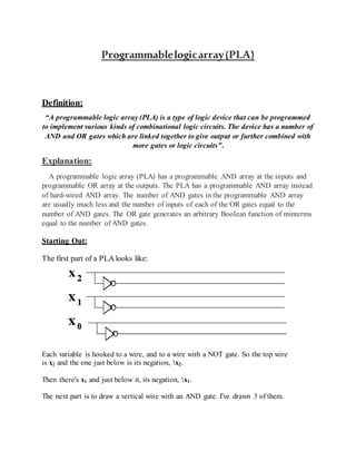
1. Programmablelogicarray(PLA)
Definition:
“A programmable logic array (PLA) is a type of logic device that can be programmed
to implement various kinds of combinational logic circuits. The device has a number of
AND and OR gates which are linked together to give output or further combined with
more gates or logic circuits”.
Explanation:
A programmable logic array (PLA) has a programmable AND array at the inputs and
programmable OR array at the outputs. The PLA has a programmable AND array instead
of hard-wired AND array. The number of AND gates in the programmable AND array
are usually much less and the number of inputs of each of the OR gates equal to the
number of AND gates. The OR gate generates an arbitrary Boolean function of minterms
equal to the number of AND gates.
Starting Out:
The first part of a PLA looks like:
Each variable is hooked to a wire, and to a wire with a NOT gate. So the top wire
is x2 and the one just below is its negation, x2.
Then there's x1 and just below it, its negation, x1.
The next part is to draw a vertical wire with an AND gate. I've drawn 3 of them.
2. Let's try to implement a truth table with a PLA.
x2 x1 x0 z1 z0
0 0 0 0 0
0 0 1 1 0
0 1 0 0 0
0 1 1 1 0
1 0 0 1 1
1 0 1 0 0
1 1 0 0 0
1 1 1 0 1
Each of the vertical lines with an AND gate corresponds to a minterm. For example, the
first AND gate (on the left) is the minterm: x2x1x0.
The second AND gate (from the left) is the minterm: x2x1x0.
The third AND gate (from the left) is the minterm: x2x1x0.
I've added a fourth AND gate which is the minterm: x2x1x0.
3. The first three minterms are used to implement z1. The third and fourth minterm are used
to implement z0.
This is how the PLA looks after we have all four minterms.
Now you might complain. How is it possible to have a one input AND gate? How can
three inputs be hooked to the same wire to an AND gate? Isn't that invalid for
combinational logic circuits?
That's true, it is invalid. However, the diagram is merely a simplification. I've drawn the
each of AND gate with three input wires, which is what it is in reality (there is as many
input wires as variables). For each connection (shown with a black dot), there's really a
separate wire. We draw one wire just to make it look neat.
4. The vertical wires are called the AND plane. We often leave out the AND gates to make
it even easier to draw.
We then add OR gates using horizontal wires, to connect the minterms together.
Example:
5. Advantages of PLA:
There is no need for the time-consuming logic design of random-logic gate
networks and even more time-consuming layout.
Design checking is easy, and design change is also easy.
Layout is far simpler than that for random-logic gate networks, and thus is far less
time-consuming.
When new IC fabrication technology is introduced, we can use previous design
information with ease but without change, making adoption of the new technology
quick and easy.
Only the connection mask needs to be custom-made.
Disadvantages of PLA:
Random-logic gate networks have higher speed than PLAs or ROMs.
Random-logic gate networks occupy smaller chip areas than PLAs or ROMs,
although the logic design and the layout of random-logic gate networks are far
more tedious and time- consuming.
Also, with large production volumes, random-logic gate networks are cheaper than
PLAs or ROMs.
Applications of PLAs:
Considering the above advantages and disadvantages, PLAs have numerous unique
applications. A micro- processor chip uses many PLAs because of easy of design change
and check. In particular, PLAs are used in its control logic, which is complex and
requires many changes, even during its design. Also, PLAs are used for code
conversions, microprogram address conversions, decision tables, bus priority resolvers,
and memory overlay.
6. Combinationallogiccircuit
In digital circuit theory, combinational logic (sometimes also referred to as time-
independent logic[1] ) is a type of digital logic which is implemented by Boolean
circuits, where the output is a pure function of the present input only. This is in contrast
to sequential logic, in which the output depends not only on the present input but also on
the history of the input. In other words, sequential logic has memory while combinational
logic does not.
Combinational logic is used in computer circuits to perform Boolean algebra on input
signals and on stored data. Practical computer circuits normally contain a mixture of
combinational and sequential logic. For example, the part of an arithmetic logic unit, or
ALU, that does mathematical calculations is constructed using combinational logic. Other
circuits used in computers, such as half adders, full adders, half subtractors, full
subtractors, multiplexers, demultiplexers, encoders and decoders are also made by
using combinational logic..
SequentialLogicCircuit
n digital circuit theory, sequential logic is a type of logic circuit whose output depends
not only on the present value of its input signals but on the sequence of past inputs, the
input history.[1][2][3][4] This is in contrast to combinational logic, whose output is a
function of only the present input. That is, sequential logic has state (memory) while
combinational logic does not.
7. Sequential logic is used to construct finite state machines, a basic building block in all
digital circuitry. Virtually all circuits in practical digital devices are a mixture of
combinational and sequential logic.
A familiar example of a device with sequential logic is a television set with "channel up"
and "channel down" buttons.[1] Pressing the "up" button gives the television an input
telling it to switch to the next channel above the one it is currently receiving. If the
television is on channel 5, pressing "up" switches it to receive channel 6. However, if the
television is on channel 8, pressing "up" switches it to channel "9". In order for the
channel selection to operate correctly, the television must be aware of which channel it is
currently receiving, which was determined by past channel selections.[1] The television
stores the current channel as part of its state. When a "channel up" or "channel down"
input is given to it, the sequential logic of the channel selection circuitry calculates the
new channel from the input and the current channel.
DifferencebetweenCombinational&SequentialCircuits
8. Combinational Logic Circuits Sequential Logic Circuits
Output is a function of the present inputs
(Time Independent Logic).
Output is a function of clock, present inputs
and the previous states of the system.
Do not have the ability to store data (state).
Have memory to store the present states
that is sent as control input (enable) for the
next operation.
It does not require any feedback. It simply
outputs the input according to the logic
designed.
It involves feedback from output to input that
is stored in the memory for the next
operation.
Used mainly for Arithmetic and Boolean
operations.
Used for storing data (and hence used in
RAM).
Logic gates are the elementary building
blocks.
Flip flops (binary storage device) are the
elementary building unit.
Independent of clock and hence does not
require triggering to operate.
Clocked (Triggered for operation with
electronic pulses).
Example: Adder [1+0=1; Dependency only
on present inputs i.e., 1 and 0].
Example: Counter [Previous O/P
+1=Current O/P; Dependency on present
input as well as previous state].
References:
https://www.techopedia.com/definition/12131/programmable-logic-array-pla
https://courses.cs.washington.edu/courses/cse370/99sp/lectures/03-
CombImpl/sld048.htm
https://en.wikipedia.org/wiki/Combinational_logic
https://en.wikipedia.org/wiki/Sequential_logic
http://www.vlsifacts.com/difference-combinational-sequential-logic-circuits/