Downloaded 238 times

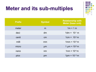
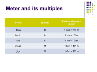
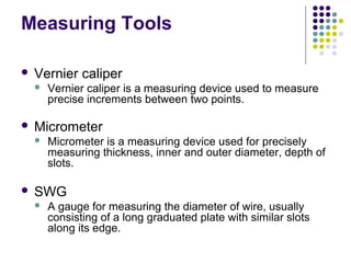
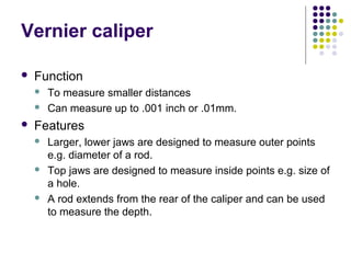
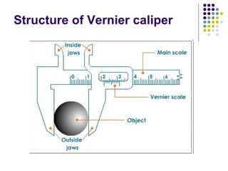
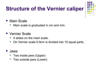
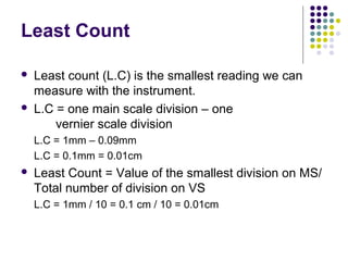
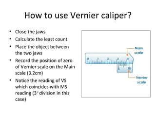
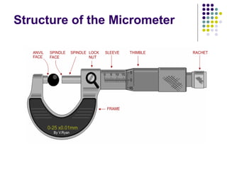
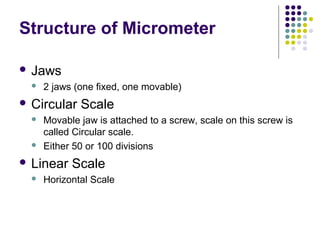
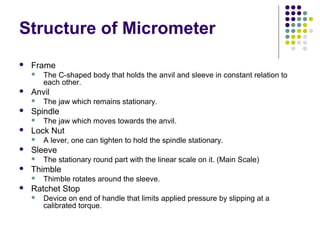
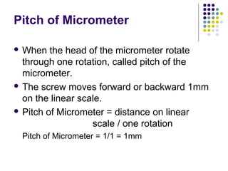
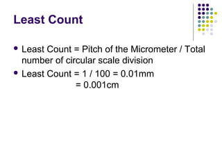
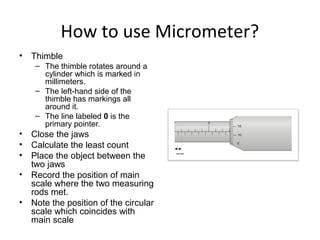
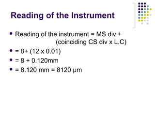
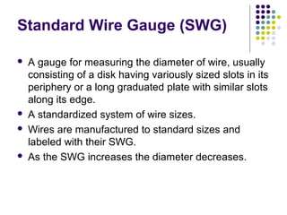
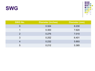


This document provides information about measuring tools used in workshops, including vernier calipers, micrometers, and standard wire gauges (SWG). It describes the structure, use, and reading of vernier calipers and micrometers. Vernier calipers can measure distances to 0.01mm using a main scale and sliding vernier scale. Micrometers have a fixed anvil and threaded spindle that moves a calibrated circular scale, allowing measurements to 0.001cm. The document also includes a table with SWG sizes for measuring wire diameters.