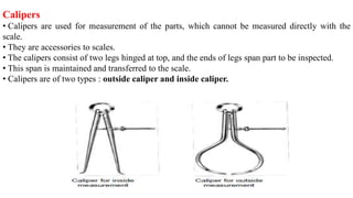
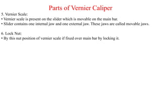
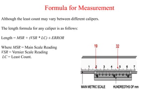
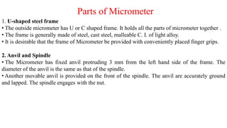
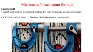
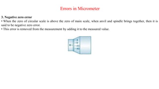
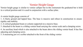
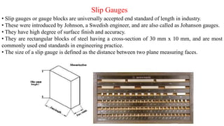
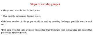
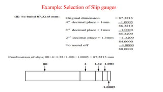
Introduction
• Linear measurement includes the measurement of lengths, diameters, heights and thickness.
• Linear measuring instruments are categorized depending upon their accuracy.
•The two categories are:
1. Non-precision instruments.
2. Precision instruments.
Non Precision Instruments
• Non-precision instruments are limited to the measurement of parts to a visible line graduation
on the instrument used.
•They are used where high measurement accuracy is not required.
Steel Rule
• It is the simplest and most common measuring instruments in inspection.
• The principle behind steel rule is of comparing an unknown length to the one previously
calibrated.
• The rule must be graduated uniformly throughout its length.
• The degree of accuracy when measurements are made by a steel rule depends upon the quality
of the rule, and the skill of the user in estimating part of a millimeter.
Calipers
• Calipers are used for measurement of the parts, which cannot be measured directly with the
scale.
• They are accessories to scales.
• The calipers consist of two legs hinged at top, and the ends of legs span part to be inspected.
• This span is maintained and transferred to the scale.
• Calipers are of two types : outside caliper and inside caliper.
Precision Measuring Instruments
• Since modern production processes is concerned with interchangeable products,
precise dimensional control is required in industry.
• Precision measurement instruments use different techniques and phenomena to
measure distance with accuracy.
Vernier Caliper
• Vernier caliper is a device that is used for precise measurement which cannot be done accurately
with the help of meter scale.
Parts of Vernier Caliper
Parts of Vernier caliper are as follows :
1. Internal Jaws:
• These are use to measure internal dimensions of a object.
• There is one pair of internal jaw.
Examples: Internal diameter of a hollow shaft, etc.
2. External Jaws:
• These are use to measure external dimensions of a object.
• There is one pair of external jaw.
Example: Diameter of a shaft, length of a specimen, etc.
3. Depth rod:
• This is use to measure the depth of a given component.
4. Main bar:
• Main bar is the part on which mail scale is present.
• One external jaw and one internal jaw is fixed with this bar. These jaws are called fixed jaws.
Parts of Vernier Caliper
5. Vernier Scale:
• Vernier scale is present on the slider which is movable on the main bar.
• Slider contains one internal jaw and one external jaw. These jaws are called movable jaws.
6. Lock Nut:
• By this nut position of vernier scale if fixed over main bar by locking it.
Vernier caliper’s least count formula
Least count:
• Least Count refers to the smallest distance that can be measured using an instrument.
• Least Count = Length of 1 MSD – Length of 1 VSD
Where
MSD is Main Scale Division
VSD is Vernier Scale Division
Generally,
N divisions on Vernier scale coincide with N-1 divisions on main scale
1 VSD is equivalent to (N-1)/N main scale divisions
Using the formula for Least Count, we get
LC = 1 MSD – 1VSD
= 1 MSD – (N-1)/N MSD
= 1/N MSD
Formula for Measurement
Although the least count may vary between different calipers.
The length formula for any caliper is as follows:
Length = MSR + (VSR * LC) ± ERROR
Where MSR = Main Scale Reading
VSR = Vernier Scale Reading
LC = Least Count.
Micrometer
•Micrometer is a device that is used for more precise measurement as compared to Vernier caliper
which cannot be done accurately with the help of meter scale.
• Micrometer works on the principle of screw and nut.
• When a screw is turned through a nut through one revolution, it advances by one pitch distance
i.e. one revolution of the screw corresponds to linear movement of a distance equal to pitch of the
thread.
Parts of Micrometer
Parts of Micrometer
1. U-shaped steel frame
• The outside micrometer has U or C shaped frame. It holds all the parts of micrometer together .
• The frame is generally made of steel, cast steel, malleable C. I. of light alloy.
• It is desirable that the frame of Micrometer be provided with conveniently placed finger grips.
2. Anvil and Spindle
• The Micrometer has fixed anvil protruding 3 mm from the left hand side of the frame. The
diameter of the anvil is the same as that of the spindle.
• Another movable anvil is provided on the front of the spindle. The anvil are accurately ground
and lapped. The spindle engages with the nut.
Parts of Micrometer
3. Lock nut
• A lock nut is provided on the micrometer spindle.
•It is used to lock the spindle when the micrometer is at its correct reading.
4. Sleeve or Barrel
•The sleeve is accurately divided and clearly marks in 0.5 mm division along its length, which
serves as main scale.
• It is chrome platted and adjustable for zero setting.
5. Thimble
• Thimble can be moved over the barrel. It has 50 equal division around its circumference. Each
division having a value of 0.01mm.
6. Ratchet
• The ratchet is provided at the end of thimble. It is used for accurate measurement.
•It creates a sound that conforms that work piece is properly fixed in the anvil and spindle.
Micrometer’s least count formula
Least count
• Least Count refers to the smallest distance that can be measured using an instrument.
• L.C = Pitch of the screw / Total no. of divisions on the circular scale.
Formula for Measurement
The formula for taking measurement by micrometer is as follows:
Measurement = MSR + (CSD * LC) ± ERROR
Where MSR = Main Scale Reading
CSR = Circular Scale Divisions
LC = Least Count.
Errors in Micrometer
Micrometer may have following types of errors:
1. Zero error
• When the zero of main scale coincides with zero of main scale.
• It means micrometer has no error or zero error.
2. Positive zero error
• When the zero of circular scale is below the zero of main scale, when anvil and spindle brings together, then it is
said to be positive zero error.
• This error is removed from the measurement by subtracting it from the measured value.
Errors in Micrometer
3. Negative zero error
• When the zero of circular scale is above the zero of main scale, when anvil and spindle brings together, then it is
said to be negative zero error.
• This error is removed from the measurement by adding it to the measured value.
Vernier Micrometer
•Some micrometers are provided with a vernier scale on the sleeve in addition to the regular
graduations.
•These permit measurements within 0.001 millimetre to be made on metric micrometers.
Vernier Height Gauge
Vernier height gauge is similar to vernier calliper but in this instrument the graduated bar is held
in a vertical position and it is used in conjunction with a surface plate.
A vernier height gauge consists of
1. A finely ground and lapped base. The base is massive and robust in construction to ensure
rigidity and stability.
2. A vertical graduated beam or column supported on a massive base.
3. Attached to the beam is a sliding vernier head carrying the vernier scale and a clamping screw.
4. An auxiliary head which is also attached to the beam above the sliding vernier head. It has fine
adjusting and clamping screw.
5. A measuring jaw or a scriber attached to the front of the sliding vernier
Vernier Height Gauge Use
Slip Gauges
Instructor
Mr. Gaurav Bharadwaj
Assistant Prof.
Department of ME
GLA University
Slip Gauges
• Slip gauges or gauge blocks are universally accepted end standard of length in industry.
• These were introduced by Johnson, a Swedish engineer, and are also called as Johanson gauges.
• They have high degree of surface finish and accuracy.
• They are rectangular blocks of steel having a cross-section of 30 mm x 10 mm, and are most
commonly used end standards in engineering practice.
• The size of a slip gauge is defined as the distance between two plane measuring faces.
Wringing in Slip Gauges
• By wringing suitable combination of two or more gauges together any dimensions may be
build-up.
•The phenomenon of wringing occurs due to molecular adhesion between a liquid film and the
mating surfaces.
•The precision of the slip gauges depends on the successful wringing
• The gap between the two pieces is observed to be 0.00635 microns which is negligible
• One gauge is placed perpendicularly on the other gauge and it is slide first followed by the
twisting motion which fits the gauges together.
• The overall thickness of the wrung gauges is equal to the sum of individual gauges.
Indian Standard of Slip Gauges
• Slip gauges are graded according to their accuracy as Grade 0, Grade I and Grade II.
• Grade II is intended for use in workshops during the actual production of components, tools and
gauges.
• Grade I is of higher accuracy and used in inspection departments.
• Grade 0 is used in laboratories and standard room which serves as standard for periodically
checking the accuracy of Grade I and Grade II gauges.
Sets of Slip Gauges
Steps to use slip gauges
• Always start with the last decimal place.
• Then take the subsequent decimal places.
•Minimum number of slip gauges should be used by selecting the largest possible block in each
step.
•If in case protector slips are used, first deduct their thickness from the required dimension then
proceed as per above order.
Example: Selection of Slip gauges
Thank you

Linear measurement

  • 1.
    Introduction • Linear measurementincludes the measurement of lengths, diameters, heights and thickness. • Linear measuring instruments are categorized depending upon their accuracy. •The two categories are: 1. Non-precision instruments. 2. Precision instruments.
  • 2.
    Non Precision Instruments •Non-precision instruments are limited to the measurement of parts to a visible line graduation on the instrument used. •They are used where high measurement accuracy is not required. Steel Rule • It is the simplest and most common measuring instruments in inspection. • The principle behind steel rule is of comparing an unknown length to the one previously calibrated. • The rule must be graduated uniformly throughout its length. • The degree of accuracy when measurements are made by a steel rule depends upon the quality of the rule, and the skill of the user in estimating part of a millimeter.
  • 3.
    Calipers • Calipers areused for measurement of the parts, which cannot be measured directly with the scale. • They are accessories to scales. • The calipers consist of two legs hinged at top, and the ends of legs span part to be inspected. • This span is maintained and transferred to the scale. • Calipers are of two types : outside caliper and inside caliper.
  • 4.
    Precision Measuring Instruments •Since modern production processes is concerned with interchangeable products, precise dimensional control is required in industry. • Precision measurement instruments use different techniques and phenomena to measure distance with accuracy.
  • 5.
    Vernier Caliper • Verniercaliper is a device that is used for precise measurement which cannot be done accurately with the help of meter scale.
  • 6.
    Parts of VernierCaliper Parts of Vernier caliper are as follows : 1. Internal Jaws: • These are use to measure internal dimensions of a object. • There is one pair of internal jaw. Examples: Internal diameter of a hollow shaft, etc. 2. External Jaws: • These are use to measure external dimensions of a object. • There is one pair of external jaw. Example: Diameter of a shaft, length of a specimen, etc. 3. Depth rod: • This is use to measure the depth of a given component. 4. Main bar: • Main bar is the part on which mail scale is present. • One external jaw and one internal jaw is fixed with this bar. These jaws are called fixed jaws.
  • 7.
    Parts of VernierCaliper 5. Vernier Scale: • Vernier scale is present on the slider which is movable on the main bar. • Slider contains one internal jaw and one external jaw. These jaws are called movable jaws. 6. Lock Nut: • By this nut position of vernier scale if fixed over main bar by locking it.
  • 8.
    Vernier caliper’s leastcount formula Least count: • Least Count refers to the smallest distance that can be measured using an instrument. • Least Count = Length of 1 MSD – Length of 1 VSD Where MSD is Main Scale Division VSD is Vernier Scale Division Generally, N divisions on Vernier scale coincide with N-1 divisions on main scale 1 VSD is equivalent to (N-1)/N main scale divisions Using the formula for Least Count, we get LC = 1 MSD – 1VSD = 1 MSD – (N-1)/N MSD = 1/N MSD
  • 9.
    Formula for Measurement Althoughthe least count may vary between different calipers. The length formula for any caliper is as follows: Length = MSR + (VSR * LC) ± ERROR Where MSR = Main Scale Reading VSR = Vernier Scale Reading LC = Least Count.
  • 10.
    Micrometer •Micrometer is adevice that is used for more precise measurement as compared to Vernier caliper which cannot be done accurately with the help of meter scale. • Micrometer works on the principle of screw and nut. • When a screw is turned through a nut through one revolution, it advances by one pitch distance i.e. one revolution of the screw corresponds to linear movement of a distance equal to pitch of the thread.
  • 11.
  • 12.
    Parts of Micrometer 1.U-shaped steel frame • The outside micrometer has U or C shaped frame. It holds all the parts of micrometer together . • The frame is generally made of steel, cast steel, malleable C. I. of light alloy. • It is desirable that the frame of Micrometer be provided with conveniently placed finger grips. 2. Anvil and Spindle • The Micrometer has fixed anvil protruding 3 mm from the left hand side of the frame. The diameter of the anvil is the same as that of the spindle. • Another movable anvil is provided on the front of the spindle. The anvil are accurately ground and lapped. The spindle engages with the nut.
  • 13.
    Parts of Micrometer 3.Lock nut • A lock nut is provided on the micrometer spindle. •It is used to lock the spindle when the micrometer is at its correct reading. 4. Sleeve or Barrel •The sleeve is accurately divided and clearly marks in 0.5 mm division along its length, which serves as main scale. • It is chrome platted and adjustable for zero setting. 5. Thimble • Thimble can be moved over the barrel. It has 50 equal division around its circumference. Each division having a value of 0.01mm. 6. Ratchet • The ratchet is provided at the end of thimble. It is used for accurate measurement. •It creates a sound that conforms that work piece is properly fixed in the anvil and spindle.
  • 14.
    Micrometer’s least countformula Least count • Least Count refers to the smallest distance that can be measured using an instrument. • L.C = Pitch of the screw / Total no. of divisions on the circular scale.
  • 15.
    Formula for Measurement Theformula for taking measurement by micrometer is as follows: Measurement = MSR + (CSD * LC) ± ERROR Where MSR = Main Scale Reading CSR = Circular Scale Divisions LC = Least Count.
  • 16.
    Errors in Micrometer Micrometermay have following types of errors: 1. Zero error • When the zero of main scale coincides with zero of main scale. • It means micrometer has no error or zero error. 2. Positive zero error • When the zero of circular scale is below the zero of main scale, when anvil and spindle brings together, then it is said to be positive zero error. • This error is removed from the measurement by subtracting it from the measured value.
  • 17.
    Errors in Micrometer 3.Negative zero error • When the zero of circular scale is above the zero of main scale, when anvil and spindle brings together, then it is said to be negative zero error. • This error is removed from the measurement by adding it to the measured value.
  • 18.
    Vernier Micrometer •Some micrometersare provided with a vernier scale on the sleeve in addition to the regular graduations. •These permit measurements within 0.001 millimetre to be made on metric micrometers.
  • 19.
    Vernier Height Gauge Vernierheight gauge is similar to vernier calliper but in this instrument the graduated bar is held in a vertical position and it is used in conjunction with a surface plate. A vernier height gauge consists of 1. A finely ground and lapped base. The base is massive and robust in construction to ensure rigidity and stability. 2. A vertical graduated beam or column supported on a massive base. 3. Attached to the beam is a sliding vernier head carrying the vernier scale and a clamping screw. 4. An auxiliary head which is also attached to the beam above the sliding vernier head. It has fine adjusting and clamping screw. 5. A measuring jaw or a scriber attached to the front of the sliding vernier
  • 20.
  • 21.
    Slip Gauges Instructor Mr. GauravBharadwaj Assistant Prof. Department of ME GLA University
  • 22.
    Slip Gauges • Slipgauges or gauge blocks are universally accepted end standard of length in industry. • These were introduced by Johnson, a Swedish engineer, and are also called as Johanson gauges. • They have high degree of surface finish and accuracy. • They are rectangular blocks of steel having a cross-section of 30 mm x 10 mm, and are most commonly used end standards in engineering practice. • The size of a slip gauge is defined as the distance between two plane measuring faces.
  • 23.
    Wringing in SlipGauges • By wringing suitable combination of two or more gauges together any dimensions may be build-up. •The phenomenon of wringing occurs due to molecular adhesion between a liquid film and the mating surfaces. •The precision of the slip gauges depends on the successful wringing • The gap between the two pieces is observed to be 0.00635 microns which is negligible • One gauge is placed perpendicularly on the other gauge and it is slide first followed by the twisting motion which fits the gauges together. • The overall thickness of the wrung gauges is equal to the sum of individual gauges.
  • 24.
    Indian Standard ofSlip Gauges • Slip gauges are graded according to their accuracy as Grade 0, Grade I and Grade II. • Grade II is intended for use in workshops during the actual production of components, tools and gauges. • Grade I is of higher accuracy and used in inspection departments. • Grade 0 is used in laboratories and standard room which serves as standard for periodically checking the accuracy of Grade I and Grade II gauges.
  • 25.
  • 26.
    Steps to useslip gauges • Always start with the last decimal place. • Then take the subsequent decimal places. •Minimum number of slip gauges should be used by selecting the largest possible block in each step. •If in case protector slips are used, first deduct their thickness from the required dimension then proceed as per above order.
  • 27.
  • 28.
  • 29.