Download as PDF, PPTX
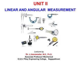
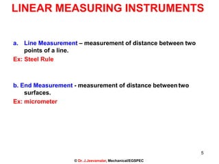
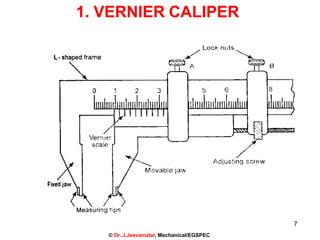
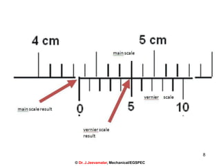
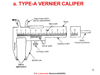
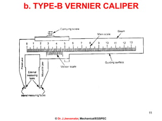
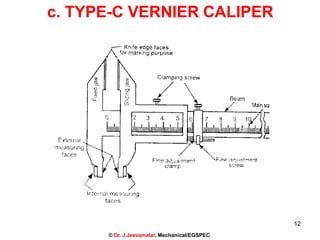

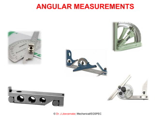


This document provides information on linear and angular measurement instruments presented by Dr. J.Jeevamalar. It discusses various linear measurement instruments like vernier calipers, micrometers, and comparators. It describes the working, types, and applications of these instruments. The document also discusses angular measuring instruments and their types including bevel protractors, clinometers, angle gauges, spirit levels, sine bars, angle telescopes, and autocollimators.