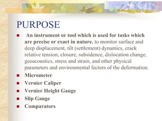
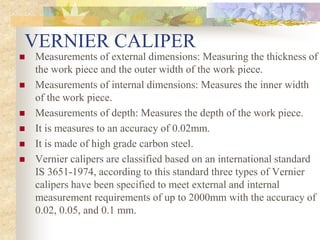
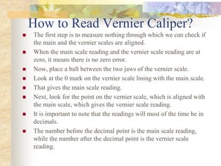
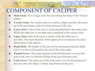
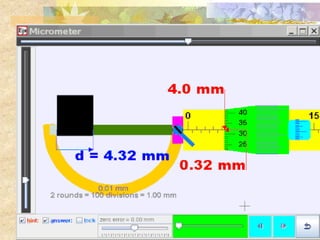
1.4: PRECISION
INSTRUMENTS
PURPOSE
 An instrument or tool which is used for tasks which
are precise or exact in nature. to monitor surface and
deep displacement, tilt (settlement) dynamics, crack
relative tension, closure, subsidence, dislocation change,
geoacoustics, stress and strain, and other physical
parameters and environmental factors of the deformation.
 Micrometer
 Vernier Caliper
 Vernier Height Gauge
 Slip Gauge
 Comparators
VERNIER CALIPER
 Measurements of external dimensions: Measuring the thickness of
the work piece and the outer width of the work piece.
 Measurements of internal dimensions: Measures the inner width
of the work piece.
 Measurements of depth: Measures the depth of the work piece.
 It is measures to an accuracy of 0.02mm.
 It is made of high grade carbon steel.
 Vernier calipers are classified based on an international standard
IS 3651-1974, according to this standard three types of Vernier
calipers have been specified to meet external and internal
measurement requirements of up to 2000mm with the accuracy of
0.02, 0.05, and 0.1 mm.
How to Read Vernier Caliper?
 The first step is to measure nothing through which we can check if
the main and the vernier scales are aligned.
 When the main scale reading and the vernier scale reading are at
zero, it means there is no zero error.
 Now, place a ball between the two jaws of the vernier scale.
 Look at the 0 mark on the vernier scale lining with the main scale.
 That gives the main scale reading.
 Next, look for the point on the vernier scale, which is aligned with
the main scale, which gives the vernier scale reading.
 It is important to note that the readings will most of the time be in
decimals.
 The number before the decimal point is the main scale reading,
while the number after the decimal point is the vernier scale
reading.
COMPONENT OF CALIPER
 Main Scale : It is a large scale that runs along the body of the Vernier
caliper.
 Vernier Scale : he vernier scale in a metric caliper can have divisions
up to 50 increments, each of which measures 0.02 mm.
 Lower Jaws : One of the jaws is fixed and attached to the main scale.
While the other jaw is movable and is attached to the vernier scale.
 Upper Jaws: One of the jaws is fixed, while the other jaw is
movable. The main function of the upper jaw is to measure the inner
dimensions of the objects.
 Depth Rod: The depths of the jars can be measured using the depth
rod. It is a thin rod located at the end of the main scale.
 Thumb Screw: The main function of the thumbscrew is to provide
grip to the users so that the sliding of the jaws becomes easy.
 Lock Screw: The main use of the lock screw is to fix the position of
the jaws once the object is firmly fixed between the jaws.
Calculation and Measurement
MICROMETER SCREW
 It is an instrument that is used for measuring the diameter of thin
wires, the thickness of small sheets such as glass or plastics.
 It is also used for accurately measuring small distances.
 Micrometer can be classified by
1. Construction /nature of measurements.
2. According to scale type
3. Output reading indication.
 Mainly three types : Inside micrometer, outside micrometer, tube
micrometers, pitch micrometer and depth micrometers.
 Generally gun metal is used for making a screw thread. The reason
is that the gun metal has least wear and tear with continuous use
over a long time. It si made by heat-treated Chromium
Vanadium Steel.
COMPONENT OF MICROMETER
 Frame : Micrometer frames are c-shaped and made of drop-
forged steel malleable cast iron.
 Anvil : The projected portion out of the frame for a distance
of at least 3mm is called anvil. it is made of alloy
 Barrel : It is fixed on the frame.
 Locking Nut : It is used to lock the spindle at a desired position.
 Spindle : It acts and grip the job against the anvil. i.e. backward
& forward.
 Thimble : It is a tubular cover attached with the spindle and
moves with the spindle.
 Ratchet Stop: It ensures a uniform pressure between the measuring
surface.
Calculation and Measurement
PRECISION  INSTRUMENTS.ppt

PRECISION INSTRUMENTS.ppt

  • 1.
  • 2.
    PURPOSE  An instrumentor tool which is used for tasks which are precise or exact in nature. to monitor surface and deep displacement, tilt (settlement) dynamics, crack relative tension, closure, subsidence, dislocation change, geoacoustics, stress and strain, and other physical parameters and environmental factors of the deformation.  Micrometer  Vernier Caliper  Vernier Height Gauge  Slip Gauge  Comparators
  • 3.
    VERNIER CALIPER  Measurementsof external dimensions: Measuring the thickness of the work piece and the outer width of the work piece.  Measurements of internal dimensions: Measures the inner width of the work piece.  Measurements of depth: Measures the depth of the work piece.  It is measures to an accuracy of 0.02mm.  It is made of high grade carbon steel.  Vernier calipers are classified based on an international standard IS 3651-1974, according to this standard three types of Vernier calipers have been specified to meet external and internal measurement requirements of up to 2000mm with the accuracy of 0.02, 0.05, and 0.1 mm.
  • 4.
    How to ReadVernier Caliper?  The first step is to measure nothing through which we can check if the main and the vernier scales are aligned.  When the main scale reading and the vernier scale reading are at zero, it means there is no zero error.  Now, place a ball between the two jaws of the vernier scale.  Look at the 0 mark on the vernier scale lining with the main scale.  That gives the main scale reading.  Next, look for the point on the vernier scale, which is aligned with the main scale, which gives the vernier scale reading.  It is important to note that the readings will most of the time be in decimals.  The number before the decimal point is the main scale reading, while the number after the decimal point is the vernier scale reading.
  • 5.
    COMPONENT OF CALIPER Main Scale : It is a large scale that runs along the body of the Vernier caliper.  Vernier Scale : he vernier scale in a metric caliper can have divisions up to 50 increments, each of which measures 0.02 mm.  Lower Jaws : One of the jaws is fixed and attached to the main scale. While the other jaw is movable and is attached to the vernier scale.  Upper Jaws: One of the jaws is fixed, while the other jaw is movable. The main function of the upper jaw is to measure the inner dimensions of the objects.  Depth Rod: The depths of the jars can be measured using the depth rod. It is a thin rod located at the end of the main scale.  Thumb Screw: The main function of the thumbscrew is to provide grip to the users so that the sliding of the jaws becomes easy.  Lock Screw: The main use of the lock screw is to fix the position of the jaws once the object is firmly fixed between the jaws.
  • 8.
  • 9.
    MICROMETER SCREW  Itis an instrument that is used for measuring the diameter of thin wires, the thickness of small sheets such as glass or plastics.  It is also used for accurately measuring small distances.  Micrometer can be classified by 1. Construction /nature of measurements. 2. According to scale type 3. Output reading indication.  Mainly three types : Inside micrometer, outside micrometer, tube micrometers, pitch micrometer and depth micrometers.  Generally gun metal is used for making a screw thread. The reason is that the gun metal has least wear and tear with continuous use over a long time. It si made by heat-treated Chromium Vanadium Steel.
  • 10.
    COMPONENT OF MICROMETER Frame : Micrometer frames are c-shaped and made of drop- forged steel malleable cast iron.  Anvil : The projected portion out of the frame for a distance of at least 3mm is called anvil. it is made of alloy  Barrel : It is fixed on the frame.  Locking Nut : It is used to lock the spindle at a desired position.  Spindle : It acts and grip the job against the anvil. i.e. backward & forward.  Thimble : It is a tubular cover attached with the spindle and moves with the spindle.  Ratchet Stop: It ensures a uniform pressure between the measuring surface.
  • 13.