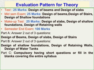
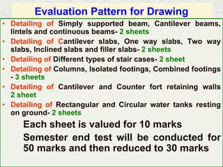
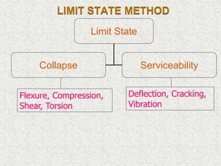
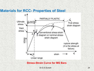
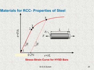
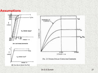
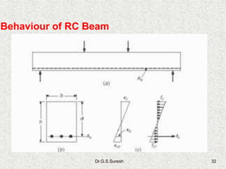
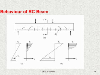
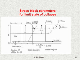
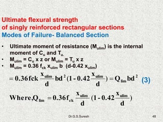
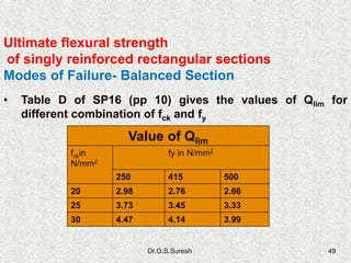
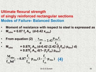
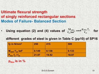
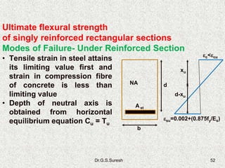
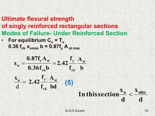
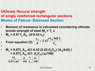
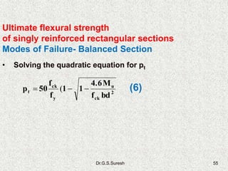
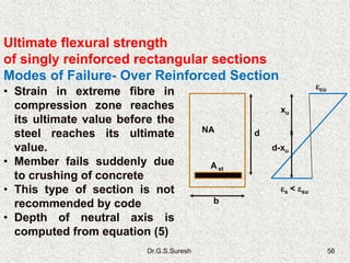
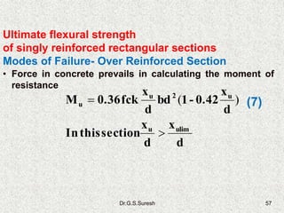
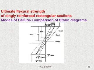
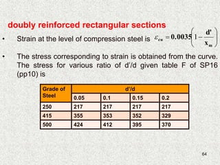
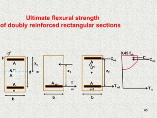
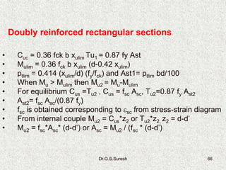
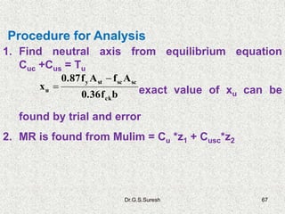
1. DESIGN & DETAILING OF RC
STRUCTURES 10CV321
Dr.G.S.Suresh, Prof, CE Dept., NIE, Mysore
2. Reference books
⢠Dr. H.J. Shah, âReinforced Concrete Vol-1â, 8th Edition,
2009.
⢠Dr. H.J. Shah, âReinforced Concrete Vol-2â, 6th Edition,
2012.
⢠S. Unnikrishna Pillai and Devadas Menon, âReinforced
Concrete Designâ, 3rd Edition, 2009
⢠P.C.Varghese, âLimit State Design of Reinforced
Concreteâ, PHI, 2nd edition, 2009
⢠Ashok K Jain, âReinforced Concrete, Limit State
Designâ, Nem Chand and Bros, 7th Edition, 2012
⢠M.L.Gambhir, âDesign of Reinforced Concrete
Structuresâ, PHI, 2008
3. Reference books Contd.
⢠Dr. B.C. Punmia et al, âLimit State Design of
Reinforced concreteâ, Laxmi, 2007.
⢠J.N. Bandyopadhyay, âDesign of Concrete Structuresâ,
PHI, 2008.
⢠N.Krishna Raju, âStructural Design and Drawing,
Reinforced concrete and steelâ, Universities Press,
1992
⢠M.R. Dheerencdra Babu, âStructural Engineering
Drawingâ, Falcon, 2011
⢠Bureau of Indian Standards, IS456-2000, IS875-1987,
SP16, SP34
4. Evaluation Pattern for Theory
⢠Test : 25 Marks: Design of beams and Design of slabs
⢠Mid sem Exam: 25 Marks: Design of beams,Design of Stairs,
Design of Shallow foundations
⢠Make-up Test : 25 Marks: Design of slabs, Design of shallow
foundations, Design of Retaining walls
⢠Semester End Exam: 100 Marks
Part A: Answer 2 out of 3 questions:
Design of Beams, Design of slabs, Design of Stairs
Part B: Answer 2 out of 3 questions:
Design of shallow foundations, Design of Retaining Walls,
Design of Water Tanks
Part C: Compulsory having short questions or fill in the
blanks covering the entire syllabus
5. Evaluation Pattern for Drawing
⢠Detailing of Simply supported beam, Cantilever beams,
lintels and continuous beams- 2 sheets
⢠Detailing of Cantilever slabs, One way slabs, Two way
slabs, Inclined slabs and filler slabs- 2 sheets
⢠Detailing of Different types of stair cases- 2 sheet
⢠Detailing of Columns, Isolated footings, Combined footings
- 3 sheets
⢠Detailing of Cantilever and Counter fort retaining walls
2 sheet
⢠Detailing of Rectangular and Circular water tanks resting
on ground- 2 sheets
Each sheet is valued for 10 marks
Semester end test will be conducted for
50 marks and then reduced to 30 marks
7. LIMIT STATE METHOD
Limit State
Collapse Serviceability
Flexure, Compression,
Shear, Torsion
Deflection, Cracking,
Vibration
8. LIMIT STATE METHOD (Contd)
⢠Different theories for different limit states
⢠WSM for serviceability limit state
⢠Ultimate Load theory for limit state of
collapse
⢠Stability analysis for overturning
⢠Provides unified rational basis
9. PROBABILISTIC ANALYSIS AND DESIGN
⢠Safety margins are provided in design to
safeguard against the risk of failure
⢠Loads and material property varies
randomly.
⢠Probability of certainty is m/n, m no of
certain events out of n events.
⢠Variations in strength of materials and in
the loads are analysed using statstical
techniques.
11. Partial Safety Factors Contd.
⢠The characteristic strength of a material
as obtained from the statistical approach
is the strength of that material below
which not more than five per cent of the
test results are expected to fall
⢠Such characteristic strengths may differ
from sample to sample also.
12. Partial Safety Factors
⢠Accordingly, the design strength is
calculated dividing the characteristic
strength further by the partial safety factor
for the material (ď§m), where ď§m depends on
the material and the limit state being
considered.
â˘
14. Partial Safety Factors Contd.
⢠Clause 36.4.2 of IS 456 states that ď§m for
concrete and steel should be taken as 1.5
and 1.15, respectively when assessing the
strength of the structures or structural
members employing limit state of collapse.
⢠However, when assessing the deflection,
the material properties such as modulus of
elasticity should be taken as those
associated with the characteristic strength
of the material.
15. Partial Safety Factors Contd.
⢠It is worth mentioning that partial safety
factor for steel (1.15) is comparatively
lower than that of concrete (1.5) because
the steel for reinforcement is produced
in steel plants and commercially
available in specific diameters with
expected better quality control than that
of concrete.
16. Partial Safety Factors Contd.
⢠In case of concrete the characteristic
strength is calculated on the basis of
test results on 150 mm standard cubes.
⢠But the concrete in the structure has
different sizes. To take the size effect
into account, it is assumed that the
concrete in the structure develops a
strength of 0.67 times the characteristic
strength of cubes.
17. Partial Safety Factors Contd.
⢠Accordingly, in the calculation of
strength employing the limit state of
collapse, the characteristic strength (fck)
is first multiplied with 0.67 (size effect)
and then divided by 1.5 (ď§m for concrete)
to have 0.446 fck as the maximum
strength of concrete in the stress block.
20. Dr.G.S.Suresh 20
⢠Tensile strength is about 10 to 20% of
compressive strength
⢠Flexure test or split tensile strength is conducted
Materials for RCC- Properties of Concrete
21. Dr.G.S.Suresh 21
⢠However, the following expression gives an
estimation of flexural strength (fcr) of concrete
from its characteristic compressive strength
(cl. 6.2.2)
Materials for RCC- Properties of Concrete
22. Dr.G.S.Suresh 22
⢠Steel in the form of circular bars (Re-bars) are
used as reinforcement to take care of tensile
stress
⢠Induces ductility
⢠Steel is strong in both compression and tension
⢠Plain bars were used earlier to 60s
⢠Plain bars have poor bond strength
⢠Deformed bars with ribs on surface are generally
used in reinforced concrete structures
Materials for RCC- Properties of Steel
23. Dr.G.S.Suresh 23
⢠High strength cold twisted (CTD)deformed (HYSD)
bars were popular for last four decades
⢠Recently Thermo mechanically treated (TMT) bars
have replaced CTD bars
⢠Yield strength is characteristic strength
⢠Characteristic strength:
MS bars-250 MPa,
CTD/TMT bars- 415MPa, 500 MPa, 550 MPa
⢠CTD bars have better elongation property
Materials for RCC- Properties of Steel
26. Dr.G.S.Suresh 26
⢠Plane sections normal to axis remain plane
after bending
⢠Maximum strain in concrete of compression
zone at failure is 0.0035
⢠Tensile strength of concrete is ignored
⢠Design curve for concrete and steel is given in
IS456-2000
⢠To ensure ductility, maximum strain in tension
reinforcement shall not be less than
0.002+fy/(1.15xEs)
⢠Perfect bond between concrete exists between
concrete and steel
Assumptions
Limit State Method of Design
30. Dr.G.S.Suresh 30
⢠Members like beam and slab are subjected
to bending moment, shear and torsion
⢠These members deforms and cracks are
developed
⢠A RC member should have perfect bond
between concrete and steel
⢠Members are primarily designed for flexure
and then checked for other forces
General aspects of Flexural Ultimate strength
31. Dr.G.S.Suresh 31
⢠Elastic theory used for homogeneous materials
cannot be used for RC members
⢠Elastic design method (WSM) do not give a clear
indication of their potential strengths
⢠Study of behaviour of members under ultimate
load has been published by several investigators
⢠Most of the codes in the world adopted Ultimate
load behaviour in 1950s
⢠IS456 introduced it in 1964
⢠Ultimate theory was later replaced by Limit state
method in IS456 during the year 1978
General aspects of Flexural Ultimate strength
34. Dr.G.S.Suresh 34
⢠Stress diagram across the depth in
compression zone up to neutral axis is called
stress block
⢠Hognested introduced the concept of stress
block
⢠Parabolic variation across the depth was
proposed
⢠Whitneyâs equivalent rectangular stress block
replaced the actual stress block.
⢠Most of the codes of other country adopt
Whitneyâs equivalent rectangular stress block
Stress block parameters
for limit state of collapse
36. Dr.G.S.Suresh 36
Stress block parameters
for limit state of collapse
1
20.002
ďĽcu=0.0035
xu
x1 = 0.57xu
x2 = 0.43xu
0.45 fck
Cu = k1 k2 fck xub
ď x
37. Dr.G.S.Suresh 37
⢠The stress block given in IS456 has
parabolic(1) and rectangular (2) portion as
shown
⢠The strain in extreme concrete fibre is
0.0035 and strain at which the stress
reaches ultimate value is 0.002
⢠From strain diagram and using similar
triangle properties
⢠From above equation x1 =0.57 x u x2=0.43 x u
Stress block parameters
for limit state of collapse
1u x
0.002
x
0.0035
ď˝
38. Dr.G.S.Suresh 38
⢠Area of stress block is A= A1 +A2
⢠A1= (2/3)*0.45*fck*xu*0.57*xu = 0.171 f ck x u
⢠A2= 0.45*fck*0.43*xu = 0.1935 xu
⢠A = A1+A2= 0.3645 fck x u
⢠Depth of Neutral axis of stress block is
obtained by taking moment of area 1 and 2
about top extreme fiber
Stress block parameters
for limit state of collapse
u
u
x43.0
A
2
x43.0
)
ď˝
ď´ďŤď´ď´
ď˝ď˝
ďĽ
ďĽď 2u1
i
ii
Ax0.57
8
3
(A
a
xa
x
39. Dr.G.S.Suresh 39
⢠Comparing the above result with the stress
block shown in figure, the stress block
parameters can be expressed as
k1= 0.45, k2=0.42, k3= 0.3645/0.45 = 0.81
Stress block parameters
for limit state of collapse
40. Dr.G.S.Suresh 40
Ultimate flexural strength
of singly reinforced rectangular sections,
ď x
T u
1
20.002
ďĽcu=0.0035
xu
x1 = 0.57xu
x2 = 0.43xu
0.45 fck
Cu
b
d
A st
z
L
NA
41. Dr.G.S.Suresh 41
Ultimate flexural strength
of singly reinforced rectangular sections
⢠Strain and Stress distribution in a beam at
mid span at ultimate load is shown
⢠For horizontal equilibrium the compressive
force (Cu) should be equal to tensile force (Tu)
⢠External ultimate moment at collapse is equal
to internal couple developed by the
compressive (Cu) and tensile force (Tu)
⢠Internal couple is called âUltimate Moment of
Resistanceâ
42. Dr.G.S.Suresh 42
Ultimate flexural strength
of singly reinforced rectangular sections
⢠From stress block parameters
Cu = 0.36 fck b xu
⢠All the tensile stress is carried by steel and
this stress is fy/ď§m = 0.87 fy
⢠If Ast is the area of steel then total tensile
force Tu = 0.87 fy Ast and from equilibrium
Cu = Tu ; 0.36 fck b xu = 0.87 fy Ast ;
bf0.36
Af0.87
x
ck
sty
u ď˝
43. Dr.G.S.Suresh 43
Ultimate flexural strength
of singly reinforced rectangular sections
⢠From equilibrium equation ďM =0, Mu = MuR
where Mu = Applied ultimate moment
MuR= Ultimate Moment of Resistance
⢠MuR = Cu x z or Tu x z;
=0.36 fck b xu z or = 0.87 fy Ast z
where z= lever arm = d-0.42 xu
44. Dr.G.S.Suresh 44
Ultimate flexural strength
of singly reinforced rectangular sections
Modes of Failure- Balanced Section
⢠Maximum strain in the two
materials reach
simultaneously and failure
would be sudden
⢠Depth of neutral axis is
maximum
⢠Maximum depth of neutral
axis is obtained from
strain diagram
ďĽcu=0.0035
ďĽsu=0.002+(0.875fy/Es)
xumax
d
A st
NA
b
d-xumax
45. Dr.G.S.Suresh 45
Ultimate flexural strength
of singly reinforced rectangular sections
Modes of Failure- Balanced Section
⢠Applying similar triangle
properties
dx
E
0.87f
0.002
x
0.0035
umax
s
y
umax ď
ďŤ
ď˝
ďĽcu=0.0035
ďĽsu=0.002+(0.875fy/Es)
xumax
d
A st
NA
b
d-xumax
s
y
umax
E
0.87f
0.0055
0.0035
x
ďŤ
ď˝
(1) ⢠Value of xumax depends
on properties of steel
46. Dr.G.S.Suresh 46
Ultimate flexural strength
of singly reinforced rectangular sections
Modes of Failure- Balanced Section
⢠Value of xumax depends on
properties of steel
⢠Clause 38.1 (pp 70) of
IS456-2000 gives value of
xumax/d for different grade of
steel
ďĽcu=0.0035
ďĽsu=0.002+(0.875fy/Es)
xumax
d
A st
NA
b
d-xumax
fy xumax/d
250 0.53
415 0.48
500 0.46
Es = 200 GPa
47. Dr.G.S.Suresh 47
Ultimate flexural strength
of singly reinforced rectangular sections
Modes of Failure- Balanced Section
⢠For equilibrium Cu = Tu
0.36 fck xumax b = 0.87fy A st max
⢠Ratio of area of steel to effective cross-section is called
percentage of steel (pt). In this case it is maximum
percentage of steel (ptmax) or limiting steel (ptlim)
y
ckumaxstmax
0.87f
f0.36
)
d
x
(
bd
A
ď´ď˝
y
ckumx
tmax
f
f
0.414
d
x
p ď´ď˝ď (2)
d
x
0.414
f
fp umx
ck
ytlim
ď˝ď (2a)
48. Dr.G.S.Suresh 48
Ultimate flexural strength
of singly reinforced rectangular sections
Modes of Failure- Balanced Section
⢠Ultimate moment of resistance (Mulim) is the internal
moment of Cu and Tu.
⢠Mulim = Cu x z or Mulim = Tu x z
⢠Mulim = 0.36 fck xulim b (d-0.42 xulim)
)(
)(
d
x
0.42-1
d
x
f0.36QWhere,
bdQ
d
x
0.42-1bd
d
x
fck0.36
ulimulim
cklim
2
lim
ulim2ulim
ď˝
ď˝ď˝ (3)
49. Dr.G.S.Suresh 49
Ultimate flexural strength
of singly reinforced rectangular sections
Modes of Failure- Balanced Section
⢠Table D of SP16 (pp 10) gives the values of Qlim for
different combination of fck and fy
Value of Qlim
fckin
N/mm2
fy in N/mm2
250 415 500
20 2.98 2.76 2.66
25 3.73 3.45 3.33
30 4.47 4.14 3.99
50. Dr.G.S.Suresh 50
Ultimate flexural strength
of singly reinforced rectangular sections
Modes of Failure- Balanced Section
⢠Moment of resistance with respect to steel is expressed as
⢠Mulim = 0.87 fy Ast (d-0.42 xulim)
⢠From equation (2)
â˘
⢠Mulim = 0.87fy Ast (d-0.42 (2.42 (fy/fck) ptlim) d)
= 0.87fy Ast d(1- (fy/fck) ptlim)
ck
ytlimumx
f
fp
2.42
d
x
ď˝ď
)p
f
f
-(1p
f
f
0.87
bdf
M
tlim
ck
y
tlim
ck
y
2
ck
ulim
ď˝ (4)
51. Dr.G.S.Suresh 51
Ultimate flexural strength
of singly reinforced rectangular sections
Modes of Failure- Balanced Section
⢠Using equation (2) and (4) values of for
different grades of steel is given in Table C (pp10) of SP16
ck
ytlim
2
ck
ulim
f
fp
and
bdf
M
fy in N/mm2 250 415 500
Mulim/ fck bd2 0.149 0.138 0.133
Ptlim fy / fck 21.97 19.82 18.87
ptlim is in %
52. Dr.G.S.Suresh 52
Ultimate flexural strength
of singly reinforced rectangular sections
Modes of Failure- Under Reinforced Section
⢠Tensile strain in steel attains
its limiting value first and
strain in compression fibre
of concrete is less than
limiting value
⢠Depth of neutral axis is
obtained from horizontal
equilibrium equation Cu = Tu
ďĽc<ďĽcu
ďĽsu=0.002+(0.875fy/Es)
xu
d
A st
NA
b
d-xu
53. Dr.G.S.Suresh 53
⢠For equilibrium Cu = Tu
0.36 fck xumax b = 0.87fy A st max
bd
A
f
f
2.42
x
b
A
f
f
2.42
bf0.36
A0.87f
x
st
ck
yu
st
ck
y
ck
sty
u
ď˝
ď˝ď˝
d
(5)
Ultimate flexural strength
of singly reinforced rectangular sections
Modes of Failure- Under Reinforced Section
d
x
d
x
sectionthisIn ulimu
ďź
54. Dr.G.S.Suresh 54
Ultimate flexural strength
of singly reinforced rectangular sections
Modes of Failure- Balanced Section
⢠Moment of resistance is calculated considering ultimate
tensile strength of steel Mu = Tu z
⢠Mu = 0.87 fy Ast (d-0.42 xu)
⢠From equation (5)
â˘
⢠Mu = 0.87fy Ast d(1-0.42 (2.42 (fy/fck) (Ast/bd)) )
= 0.87fy Ast d(1- (fy/fck) pt/100)
ck
ystu
f
f/bd)(A
2.42
d
x
ď˝ď
2
ďˇ
ď¸
ďś
ď§
ď¨
ďŚ
ď˝
100
p
f
f
-
100
p
bdf0.87
M t
ck
yt
2
y
u
55. Dr.G.S.Suresh 55
Ultimate flexural strength
of singly reinforced rectangular sections
Modes of Failure- Balanced Section
⢠Solving the quadratic equation for pt
(6)2
ck
u
y
ck
t
bdf
M4.6
11
f
f
50p ďďď˝ (
56. Dr.G.S.Suresh 56
Ultimate flexural strength
of singly reinforced rectangular sections
Modes of Failure- Over Reinforced Section
⢠Strain in extreme fibre in
compression zone reaches
its ultimate value before the
steel reaches its ultimate
value.
⢠Member fails suddenly due
to crushing of concrete
⢠This type of section is not
recommended by code
⢠Depth of neutral axis is
computed from equation (5)
ďĽcu
ďĽs < ďĽsu
xu
d
A st
NA
b
d-xu
57. Dr.G.S.Suresh 57
Ultimate flexural strength
of singly reinforced rectangular sections
Modes of Failure- Over Reinforced Section
⢠Force in concrete prevails in calculating the moment of
resistance
)(
d
x
0.42-1bd
d
x
fck0.36M u2u
u ď˝
d
x
d
x
sectionthisIn ulimu
ďž
(7)
58. Dr.G.S.Suresh 58
Ultimate flexural strength
of singly reinforced rectangular sections
Modes of Failure- Comparison of Strain diagrams
⢠Position of neutral axis in case of under reinforced
section is above the position of balanced section and in
case of over reinforced section it is below the position of
balanced section
60. Dr.G.S.Suresh 60
Ultimate flexural strength
of singly reinforced rectangular sections
Beam with very small amount of steel- Minimum Steel
⢠Section is large and intensity of loading is small
⢠If designed steel is provided, failure is brittle
⢠To prevent brittle failure minimum steel is required
⢠Clause 26.5.1.1 a (pp47) of IS 456 stipulates minimum
steel as
61. 61
Ultimate flexural strength
of doubly reinforced rectangular sections
dâ
T u
1
2ďĽsc
ďĽcu=0.0035
xu
x1 = 0.57xu
x2 = 0.43xu
0.45 fck
Cuc
b
d
A st
z
L
NA
A sc
0.002
Cus
62. 62
Doubly reinforced rectangular sections
⢠Two alternatives when applied moment is > than
Mulim
1. To increase the depth of section
2. To provide compression reinforcement
⢠The beam with its limited depth, if reinforced on the
tension side only, may not have enough moment of
resistance, to resist the bending moment.
⢠Architectural or other consideration restricts the
depth of section
63. 63
Doubly reinforced rectangular sections
⢠By increasing the quantity of steel in the tension zone, the
moment of resistance cannot be increased indefinitely.
Usually, the moment of resistance can be increased by not
more than 25% over the balanced moment of resistance, by
making the beam over-reinforced on the tension side.
⢠Hence, in order to further increase the moment of resistance
of a beam section of unlimited dimensions, a doubly
reinforced beam is provided.
⢠The external live loads may alternate i.e. may occur on either
face of the member.
64. 64
doubly reinforced rectangular sections
⢠Strain at the level of compression steel is
⢠The stress corresponding to strain is obtained from the curve.
The stress for various ratio of dâ/d given table F of SP16
(pp10) is
ďˇďˇ
ď¸
ďś
ď§ď§
ď¨
ďŚ
ďď˝
m
cu
x
d'
0.0035 1ďĽ
Grade of
Steel
dâ/d
0.05 0.1 0.15 0.2
250 217 217 217 217
415 355 353 352 329
500 424 412 395 370
65. 65
Ultimate flexural strength
of doubly reinforced rectangular sections
b
T u
0.45 fck
Cuc
Cus
Cuc
+
T u2
dâ
xu
d
A
st
N
A
A
sc
b
z1
A st1
b
z2
A
st2
A
sc
T
uc
=
Cus
66. Dr.G.S.Suresh 66
Doubly reinforced rectangular sections
⢠Cuc = 0.36 fck b xulim Tu1 = 0.87 fy Ast
⢠Mulim = 0.36 fck b xulim (d-0.42 xulim)
⢠ptlim = 0.414 (xulim/d) (fy/fck) and Ast1= ptlim bd/100
⢠When Mu > Mulim then Mu2 = Mu-Mulim
⢠For equilibrium Cus =Tu2 , Cus = fsc Asc, Tu2=0.87 fy Ast2
⢠Ast2= fsc Asc/(0.87 fy)
⢠fsc is obtained corresponding to ďĽsc from stress-strain diagram
⢠From internal couple Mu2 = Cus*z2 or Tu2*z2, z2 = d-dâ
⢠Mu2 = fsc*Asc* (d-dâ) or Asc = Mu2 / (fsc * (d-dâ)
67. Dr.G.S.Suresh 67
1. Find neutral axis from equilibrium equation
Cuc +Cus = Tu
exact value of xu can be
found by trial and error
2. MR is found from Mulim = Cu *z1 + Cusc*z2
Procedure for Analysis
bf0.36
AfAf0.87
x
ck
scscsty
u
ď
ď˝
68. Dr.G.S.Suresh 68
1. Check for need for doubly reinforced beam, ie.,
Mu >Mulim
2. Find Ast1 = Astlim using equation (2)
3. Mu2 = Mu-Mulim
4. Compute Asc = Mu2/(fsc (d-dâ)) obtain fsc
corresponding to ďĽsc obtained from table F of
SP16
5. Additional tension required is obtained from
equilibrium equation Ast2 = fsc Asc/(0.87fy)
6. Total tension steel Ast = Ast1 + Ast2
Procedure for design
69. Dr.G.S.Suresh 69
1. Table 45 to 56 (pp 81-92) of SP16 gives pt and pc
for different value of Mu/(bd2)
Use of SP-16
70. 70
⢠Reinforced concrete slabs used in floors, roofs
and decks are mostly cast monolithic from the
bottom of the beam to the top of the slab.
⢠Such rectangular beams having slab on top are
different from others having either no slab
(bracings of elevated tanks, lintels etc.) or
having disconnected slabs as in some pre-cast
systems (Figs. a, b and c).
⢠Due to monolithic casting, beams and a part of
the slab act together. Under the action of
positive bending moment, i.e., between the
supports of a continuous beam, the slab, up to a
certain width greater than the width of the beam,
forms the top part of the beam.
Introduction to flanged sections
71. 71
Introduction to flanged sections
a) Bracing of elevated Water tank
b) Lintel without effective chajjas
c) Precast slab on rectangular beams
72. 72
⢠Such beams having slab on top of the rectangular rib are
designated as the flanged beams - either T or L type
depending on whether the slab is on both sides or on one
side of the beam. Over the supports of a continuous beam,
the bending moment is negative and the slab, therefore, is in
tension while a part of the rectangular beam (rib) is in
compression. The continuous beam at support is thus
equivalent to a rectangular beam (Fig d to i)
Introduction to flanged sections
79. 79
⢠The actual width of the flange is the spacing of
the beam, which is the same as the distance
between the middle points of the adjacent spans
of the slab, as shown in Fig. e. However, in a
flanged beam, a part of the width less than the
actual width, is effective to be considered as a
part of the beam. This width of the slab is designated
as the effective width of the flange.
Introduction to flanged sections
81. 81
IS code requirements
The following requirements (cl. 23.1.1 of IS 456)
are to be satisfied to ensure the combined action
of the part of the slab and the rib (rectangular part of
the beam).
(a) The slab and the rectangular beam shall be cast
integrally or they shall be effectively bonded in any
other manner.
(b) Slabs must be provided with the transverse
reinforcement of at least 60 percent of the main
reinforcement at the mid span of the slab if
the main reinforcement of the slab is parallel to the
transverse beam (Figs. a and b).
Introduction to flanged sections
84. 84
Ultimate flexural strength of flanged
sections: T-beam
⢠Analysis of T-beam depends on the position of neutral axis.
⢠The neutral axis of a flanged beam may be either in the
flange or in the web depending on the physical
dimensions of the effective width of flange bf, effective
width of web bw, thickness of flange Df and effective depth
of flanged beam d .
⢠The flanged beam may be considered as a rectangular
beam of width bf and effective depth d if the neutral axis
is in the flange as the concrete in tension is ignored.
⢠However, if the neutral axis is in the web, the
compression is taken by the flange and a part of the web.
86. 86
Ultimate flexural strength of
flanged sections:T-beam
⢠All the assumptions made in sec. 3.4.2 of Rectangular sections
are also applicable for the flanged beams.
⢠The compressive stress remains constant between the strains
of 0.002 and 0.0035.
⢠It is important to find the depth h of the beam where the strain is
0.002
⢠If it is located in the web, the whole of flange will be under
the constant stress level of 0.446 fck.
⢠The relation of Df and d to facilitate the determination
of the depth h where the strain will be 0.002 similar triangle
properties is applied to strain diagram.
88. 88
Ultimate flexural strength of flanged
sections:T-beam
⢠Hence the three values of h are around 0.2 d for the three
grades of steel.
⢠The maximum value of h may be Df, at the bottom of the
flange where the strain will be 0.002, if Df /d = 0.2.
⢠The thickness of the flange may be considered small if Df /d
does not exceed 0.2 and in that case, the position of the fibre
of 0.002 strain will be in the web and the entire flange will be
under a constant compressive stress of 0.446 fck .
⢠On the other hand, if Df is > 0.2 d, the position of the fibre of
0.002 strain will be in the flange. In that case, a part of the slab
will have the constant stress of 0.446 fck where the strain will
be more than 0.002.
89. 89
Ultimate flexural strength of flanged
sections-Tbeam
⢠Thus, in the balanced and over-reinforced flanged
beams (when xu = xu,max), the ratio of Df /d is important to
determine if the rectangular stress block is for the full depth of
the flange (when Df /d does not exceed 0.2) of for a part of the
flange (when Df /d > 0.2).
⢠Similarly, for the under-reinforced flanged beams, the ratio of
Df /xu is considered in place of Df /d.
⢠If Df /xu does not exceed 0.43, the constant stress block is for
the full depth of the flange.
⢠If Df /xu > 0.43, the constant stress block is for a part of the
depth of the flange.
91. 91
T-beam: Case-2, xu>Df and (Df /d) ďŁ 0.2
⢠In this case the rectangular portion of the stress block is
greater than that of flange thickness
1
2 2
1
92. 92
T-beam: Case-2, xu>Df and (Df /d) ďŁ 0.2
⢠C= force of portion 1 + 2 x force of portion 2
= 0.36 fck bw xulim + 0.45 fck (bf-bw) Df
T = 0.87 fy Ast
Mulim = Mu1+ Mu2
= 0.36 fck bw xulim (d-0.42 xulim) + 0.45 fck (bf-bw) Df (d-Df/2)
94. T-beam: Case-3, xu>Df and (Df /d) > 0.2
⢠In this case the depth of rectangular portion of stress block is
within flange and part of parabolic portion lies within flange
⢠Equating the areas of actual stress block o equivalent stress
block, yf = 0.142 xu +0.67 Df
As per IS456-2000 yf = 0.15 xu + 0.65 Df
⢠C= force of portion 1 + 2 x force of portion 2
= 0.36 fck bw xulim + 0.45 fck (bf-bw) yf
T = 0.87 fy Ast
Mulim = Mu1+ Mu2
= 0.36 fck bw xulim (d-0.42 xulim) + 0.45 fck (bf-bw) yf (d-yf/2)
95. T-beam: Case-4, xumax >xu>Df
⢠When Df/xu ďŁ 0.43, use equation of case-2 other
wise use equation of case-3. In both cases use
xumax in place of xu
96. 96
Ultimate shear strength of RC sections
⢠Shear force in a beam is due to change in BM along the
length
⢠Shear and BM act together
⢠Generally in design the strength is governed by flexure and
the section is checked for shear
⢠Failure due to shear is sudden
⢠Most of the codes recommends the equations based on
laboratory tests
⢠Shear and flexural stress induce principal stress called as
diagonal tension
97. 97
Ultimate shear strength of RC sections
⢠Before cracking the RC beam acts similar to homogeneous
material
⢠The flexural and shear stress at any point across the depth is
computed as f=M y /I, q= F(Aď y)/ Ib
⢠Flexural stress varies linearly and shear stress varies
parabolically with max stress being at neutral axis
⢠These stresses acting on element is indicated in sketch
fcfc
q
q
q
q
ft
q
q
ft
Compression zone Neutral Axis Tension zone
98. 98
Ultimate shear strength of RC sections
⢠After the concrete cracks, variation of shear stress across the
depth is complex.
⢠The nominal shear stress in beams of uniform depth shall be
obtained by the following equation:
⢠Nominal shear strength ď´v should not exceed the maximum
shear stress ď´cmax given in table 20 of IS 456. If it exceeds
then the depth of the beam to be revised
⢠Shear reinforcement in the form of stirrups or cranked bars is
provided to take care of diagonal tension developed
⢠The design shear strength of concrete ď´c in beams without
shear reinforcement is given in Table 19 of IS456-2000
101. 101
Ultimate shear strength of RC sections
⢠If ď´v < ď´c then nominal shear reinforcement given in clause
26.5.1.6 page 48 to be provided. Minimum shear
reinforcement as per this clause is
⢠When ď´v > ď´c then design of shear reinforcement is required
⢠The applied ultimate shear force is resisted by both concrete
and steel. If Vu is the applied shear force, Vcu is the shear
resistance of concrete and Vsu is the shear resistance of
steel then Vu = Vcu + Vsu
⢠Vcu = ď´c bd
⢠Computation for different form of shear reinforcement is given
in clause 40.4 of IS456 page 72 and 73
103. 103
Ultimate shear strength of RC sections
⢠Where more than one type of shear reinforcement is used
to reinforce the same portion of the beam, the total shear
resistance shall be computed as the sum of the reistance
for the various types separately
⢠Where bent-up bars are provided, their contribution
towards shear resistance shall not be more than half that of
total shear reinforcement
104. Ultimate shear strength of RC sections
Procedure for design of shear in RCC
1. The ultimate shear force acting at critical section (ie., d from
face of support) is calculated as Vu
2. Calculate the nominal shear stress as ď´v = Vu /bd, ď´v ďŁ ď´vmax
3. From the flexural design result calculate the percentage of
steel provided as pt = 100 Ast / bd and obtain the shear
strength of concrete ď´c from table 19 page 73 of IS 456-2000
4. The shear strength of concrete is calculated as Vcu = ď´c bd
5. If ď´v < ď´c then provide nominal shear reinforcement as specified
26.5.1.6 page 48
6. If ď´v >ď´c then design the shear reinforcement as in clause 40.4
105. Ultimate torsion strength of RC sections
⢠Moment about axis of the beam is torsion
1. Corner lintels
2. Curved beams
3. Balcony beams supporting slabs
4. L-Beams
5. Spiral staircase
6. Non rectangular 3D structures
⢠Classified as Equilibrium torsion and Compatibility torsion
⢠Equilibrium torsion occurs in statically determinate structures
⢠Compatibility torsion occurs in both determinate and
indeterminate structures
107. Ultimate torsion strength of RC sections
⢠Elastic Torsion equation for circular section is
⢠Torsion induces shear and in turn induces principal tensile
stress
⢠When the magnitude of principal tensile stress is more than
modulus of rupture of concrete, diagonal cracks are induced
⢠These cracks spiral around the beam
R
f
L
G
I
T s
P
ď˝ď˝
ďą
108. Ultimate torsion strength of RC sections
⢠The torsional resistance of plain concrete can be
improved by providing suitable reinforcement
⢠Combination of longitudinal reinforcement and
stirrups are provided
⢠Design equations are based on space truss
analogy proposed by Lampert and Collins
⢠Case of pure torsion does not occur
⢠Combination of Flexure, Shear and Torsion is
considered
⢠For design equivalent shear force and bending
moment are computed
109. Ultimate torsion strength of RC sections
⢠Equivalent bending moment is Me1 = Mu + Mt
Where, Mu = Ultimate external Bending Moment
Mt = Tu (1+D/b)/1.7
D = Overall depth
b = Width of section
Longitudinal reinforcement is designed for Me1
⢠When numerical value of Mt exceeds numerical value of Mu,
longitudinal reinforcement is provided on compression face
also for Me2 = Mt - Mu
⢠Equivalent shear is Ve= Vu + 1.6 (Tu/b)
⢠Equivalent nominal shear ď´ve = Ve /bd
⢠ď´ve should not exceed ď´cmax given in table 20 page 73 of IS456-
2000
110. Ultimate torsion strength of RC sections
⢠If ď´ve >ď´c (of table 19 page 73 of Is456-2000) then transverse
reinforcement is provided
⢠Two legged closed hoops enclosing the corner longitudinal
bars shall have c/s area Asv given by
⢠The total transverse reinforcement shall be less than
)f87.o(d5.2
sV
)f87.0(db
sT
A
y1
vu
y11
vu
sv ďŤď˝
y
vcve
f87.0
bs)( ď´ď´ ď
112. Ultimate torsion strength of RC sections
⢠The transverse reinforcement for torsion shall be rectangular
closed stirrups shall be closed stirrups placed perpendicular to
axis of members.
⢠The spacing of stirrups shall not exceed the least of
1. x1
2. (x1+y1)/4
3. 300 mm
x1 and y1 are short and long dimensions of the stirrups
⢠The longitudinal reinforcement shall be placed as close as
practicable to the corners of the cross section and there shall
be at least one longitudinal bar in each corner of the ties
113. Concepts of Development
Length and Anchorage
⢠The bond between steel and concrete is very important and
essential so that they can act together without any slip in a
loaded structure.
⢠With the perfect bond between them, the plane section of a
beam remains plane even after bending.
⢠The length of a member required to develop the full bond is
called the anchorage length.
⢠The bond is measured by bond stress.
⢠The local bond stress varies along a member with the variation
of bending moment.
114. Concepts of Development
Length and Anchorage
â˘The average value throughout its anchorage length is
designated as the average bond stress.
â˘Thus, a tensile member has to be anchored properly by providing
additional length on either side of the point of maximum tension,
which is known as âDevelopment length in tensionâ.
â˘Similarly, for compression members also, we have âDevelopment
length Ld in compressionâ.
115. Concepts of Development
Length and Anchorage
â˘The deformed bars are known to be superior to the smooth mild
steel bars due to the presence of ribs.
â˘In such a case, it is needed to check for the sufficient
development length Ld only rather than checking both for the local
bond stress and development length as required for the smooth
mild steel bars.
â˘Accordingly, IS 456, cl. 26.2 stipulates the requirements of proper
anchorage of reinforcement in terms of development length Ld
only employing design bond stress ď´bd.
116. Concepts of Development
Length and Anchorage
Design Bond Stress ď´bd
⢠The design bond stress ď´bd is defined as the shear force per
unit nominal surface area of reinforcing bar. The stress is
acting on the interface between bars and surrounding concrete
and along the direction parallel to the bars.
⢠This concept of design bond stress finally results in additional
length of a bar of specified diameter to be provided beyond a
given critical section.
117. Concepts of Development
Length and Anchorage
Design Bond Stress ď´bd
⢠Though, the overall bond failure may be avoided by this
provision of additional development length Ld, slippage of a bar
may not always result in overall failure of a beam.
⢠It is, thus, desirable to provide end anchorages also to maintain
the integrity of the structure and thereby, to enable it carrying
the loads.
⢠Clause 26.2 of IS 456 stipulates, âThe calculated tension or
compression in any bar at any section shall be developed on
each side of the section by an appropriate development length
or end anchorage or by a combination thereof.â
118. Concepts of Development
Length and Anchorage
Design bond stress â values
⢠The local bond stress varies along the length of the reinforcement
while the average bond stress gives the average value throughout
its development length.
⢠The average bond stress has been designated as design bond
stress ď´bd and the values are given in cl. 26.2.1.1. The same is
For deformed bars conforming to IS 1786, these values shall be
increased by 60 per cent. For bars in compression, the values of
bond stress in tension shall be increased by 25 per cent.
120. Concepts of Development
Length and Anchorage
(a) A single bar
⢠Figure (a) shows a simply supported beam subjected to
uniformly distributed load. Because of the maximum moment,
the Ast required is the maximum at x = L/2. For any section 1-1
at a distance x < L/2, some of the tensile bars can be curtailed.
⢠Let us then assume that section 1-1 is the theoretical cut-off
point of one bar. However, it is necessary to extend the bar for
a length Ld as explained earlier. Let us derive the expression to
determine Ld of this bar.
121. Concepts of Development
Length and Anchorage
⢠Figure (b) shows the free body diagram of the segment AB of
the bar. At B, the tensile force T trying to pull out the bar is of
the value T = (Ď Ď2 Ďs /4)
where Ď is the nominal diameter of the bar and Ďs is the tensile
stress in bar at the section considered at design loads.
⢠It is necessary to have the resistance force to be developed by
Ďbd for the length Ld to overcome the tensile force. The
resistance force = Ď Ď (Ld) (ď´bd).
⢠Equating the two,
â˘ Ď Ď (Ld) (ď´bd) = (Ď Ď2 Ďs /4)
122. Concepts of Development
Length and Anchorage
⢠The above equation is given in cl. 26.2.1 of IS 456 to determine
the development length of bars. Table 65 of SP16 gives value
of Ld
123. Concepts of Development
Length and Anchorage
⢠The above equation is given in cl. 26.2.1 of IS 456 to determine
the development length of bars.
Checking of Development Lengths of Bars in Tension
The following are the stipulation of cl. 26.2.3.3 of IS 456.
(i) At least one-third of the positive moment reinforcement in
simple members and one-fourth of the positive moment
reinforcement in continuous members shall be extended
along the same face of the member into the support, to a
length equal to Ld/3.
124. Concepts of Development
Length and Anchorage
(ii) Such reinforcements of (i) above shall also be anchored to
develop its design stress in tension at the face of the
support, when such member is part of the primary lateral load
resisting system.
(iii) The diameter of the positive moment reinforcement shall
be limited to a diameter such that the Ld computed for Ďs = fd
in Eq. for Ld does not exceed the following:
where M1 = moment of resistance of the section assuming all
reinforcement at the section to be stressed to fd,
fd = 0.87 fy, V = shear force at the section due to design loads,
125. Concepts of Development
Length and Anchorage
Lo = sum of the anchorage beyond the centre of the support and
the equivalent anchorage value of any hook or mechanical
anchorage at simple support.
At a point of inflection, Lo is limited to the effective depth of the
member or 12Ď, whichever is greater, and
Ď = diameter of bar.
It has been further stipulated that M1/V in the above expression
may be increased by 30 per cent when the ends of the
reinforcement are confined by a compressive reaction.
126. Concepts of Development
Length and Anchorage
Anchoring Reinforcing Bars
The bars may be anchored in combination of providing
development length to maintain the integrity of the structure. Such
anchoring is discussed below under three sub-sections for bars in
tension, compression and shear respectively, as stipulated in cl.
26.2.2 of IS 456.
128. Concepts of Development
Length and Anchorage
The salient points are:
⢠Deformed bars may not need end anchorages if the
development length requirement is satisfied.
⢠Hooks should normally be provided for plain bars in tension.
⢠Standard hooks and bends should be as per IS 2502 or as given
in Table 67 of SP-16, which are shown in Figs.
⢠The anchorage value of standard bend shall be considered as 4
times the diameter of the bar for each 45o bend subject to a
maximum value of 16 times the diameter of the bar.
⢠The anchorage value of standard U-type hook shall be 16 times
the diameter of the bar.
129. Concepts of Development
Length and Anchorage
Bars in compression (cl. 26.2.2.2 of IS 456)
Here, the salient points are:
⢠The anchorage length of straight compression bars shall be
equal to its development length.
⢠The development length shall include the projected length of
hooks, bends and straight lengths beyond bends, if provided.
131. Concepts of Development Length and Anchorage
The salient points are:
⢠Inclined bars in tension zone will have the development length
equal to that of bars in tension and this length shall be measured
from the end of sloping or inclined portion of the bar.
⢠Inclined bars in compression zone will have the development
length equal to that of bars in tension and this length shall be
measured from the mid-depth of the beam.
⢠For stirrups, transverse ties and other secondary reinforcement,
complete development length and anchorage are considered to
be satisfied if prepared as shown in Figs.
132. Control of Deflection
The deflection of beams and slabs would generally be,
within permissible limits if the ratio of span to effective
depth of the
member does not exceed the values obtained in
accordance with 22.2.1 of the Code. The following basic
values of span to effective
depth are given:
Simply supported------------------------------- 20
Continuous--------------------------------------- 26
Cantilever ---------------------------------------- 7
Correction factors for tension steel, compression
steel and flanged section are to be used on these
values
133. Control of Deflection
Chart 22 of SP16 gives l/d after correction for tension
steel and compression steel.The values read from these
Charts are directly applicable for simply supported
members of rectangular cross section for spans up to 10
m. For simply supported or continuous spans larger than
10 m, the values should be further multiplied by the
factor (10/span in meters). For continuous spans or
cantilevers, the values read from the charts are to be
modified in proportion to the basic values of span to
effective depth ratio. 1.3 for continuous beam and 0.35
for cantilever.
In the case of cantilevers which are longer than 10 m the
Code recommends that the deflections should be
calculated in order to ensure that they do not exceed
permissible limits