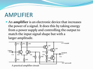
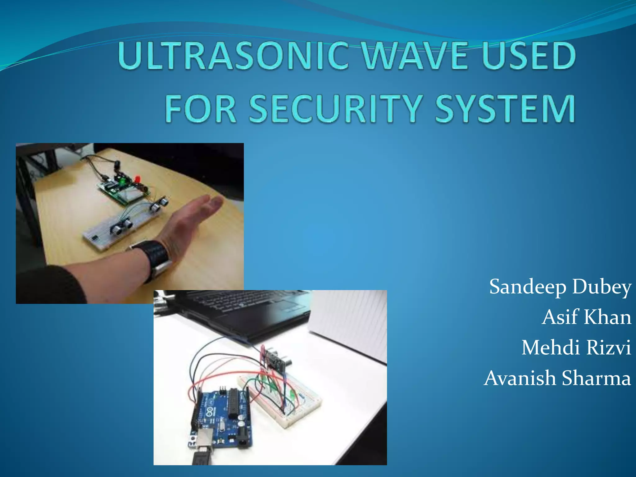
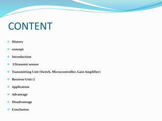
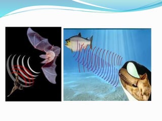
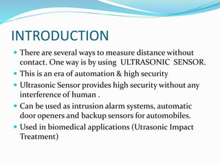
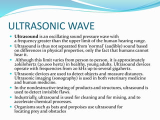
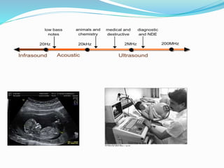
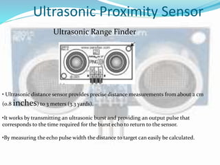
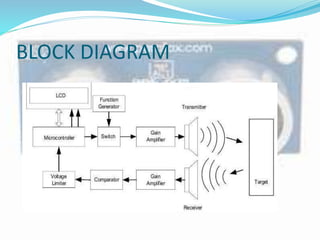
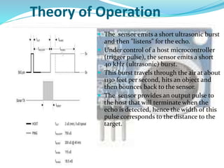
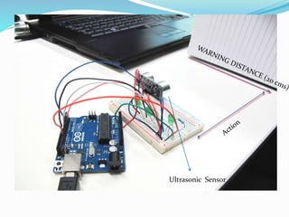
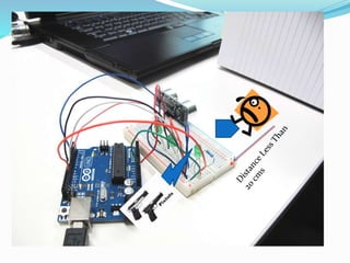
Sandeep Dubey
Asif Khan
Mehdi Rizvi
Avanish Sharma
CONTENT
 History
 concept
 Introduction
 Ultrasonic sensor
 Transmitting Unit (Switch, Microcontroller, Gain Amplifier)
 Receiver Unit ()
 Application
 Advantage
 Disadvantage
 Conclusion
HISTORY
 Acoustics, the science of sound, starts as far back
as Pythagoras in the 6th century BC, who wrote on
the mathematical properties of stringed instruments.
 Sir Francis Galton constructed a whistle producing
ultrasound in 1893.
 The first technological application of ultrasound was an
attempt to detect icebergs by Paul Langevin in 1917.
 The piezoelectric effect, discovered by Jacques and Pierre
Curie in 1880, was useful in transducers to generate and
detect ultrasonic waves in air and water.
 Echolocation in bats was discovered by Lazzaro
Spallanzani in 1794, when he demonstrated that bats
hunted and navigated by inaudible sound and not vision.
CONCEPT
 Bats use a variety of ultrasonic ranging ( echolocation )
techniques to detect their prey. They can detect
frequencies beyond 100 kHz, possibly up to 200 kHz.
 Toothed whales , including dolphins, can hear
ultrasound and use such sounds in their navigational
system (biosensor) to orient and capture prey.
INTRODUCTION
 There are several ways to measure distance without
contact. One way is by using ULTRASONIC SENSOR.
 This is an era of automation & high security
 Ultrasonic Sensor provides high security without any
interference of human .
 Can be used as intrusion alarm systems, automatic
door openers and backup sensors for automobiles.
 Used in biomedical applications (Utrasonic Impact
Treatment)
ULTRASONIC WAVE
 Ultrasound is an oscillating sound pressure wave with
a frequency greater than the upper limit of the human hearing range.
 Ultrasound is thus not separated from 'normal' (audible) sound based
on differences in physical properties, only the fact that humans cannot
hear it.
 Although this limit varies from person to person, it is approximately
20kilohertz (20,000 hertz) in healthy, young adults. Ultrasound devices
operate with frequencies from 20 kHz up to several gigahertz.
 Ultrasonic devices are used to detect objects and measure distances.
Ultrasonic imaging (sonography) is used in both veterinary medicine
and human medicine.
 In the nondestructive testing of products and structures, ultrasound is
used to detect invisible flaws.
 Industrially, ultrasound is used for cleaning and for mixing, and to
accelerate chemical processes.
 Organisms such as bats and porpoises use ultrasound for
locating prey and obstacles
Ultrasonic Proximity Sensor
Ultrasonic Range Finder
• Ultrasonic distance sensor provides precise distance measurements from about 2 cm
(0.8 inches) to 3 meters (3.3 yards).
•It works by transmitting an ultrasonic burst and providing an output pulse that
corresponds to the time required for the burst echo to return to the sensor.
•By measuring the echo pulse width the distance to target can easily be calculated.
BLOCK DIAGRAM
Simple to Connect
Theory of Operation
 The sensor emits a short ultrasonic burst
and then "listens" for the echo.
 Under control of a host microcontroller
(trigger pulse), the sensor emits a short
40 kHz (ultrasonic) burst.
 This burst travels through the air at about
1130 feet per second, hits an object and
then bounces back to the sensor.
 The sensor provides an output pulse to
the host that will terminate when the
echo is detected, hence the width of this
pulse corresponds to the distance to the
target.
Detection Range Limit
TRANSMITTING UNIT
 MICROCONTROLLER
 GAIN AMPLIFIER
 SWITCH
MICROCONTROLLER (8051)
MICROCONTROLLER
 A smaller computer.
 On-Chip RAM,ROM,I/O ports
 A microcontroller (sometimes abbreviated µC, or MCU)
is a small computer on a single integrated circuit
containing a processor core,
memory, and programmable
input/output peripherals.
Block Diagram of Microcontroller
SWITCH
 An analog switch CD4066 is used to allow the sine
wave from function generator to the gain amplifier.
 The excitation to the Transmitter is given from the
Function generator through the switch which can be
digitally controlled. As the switch can pass only
positive voltages, the 40kHz, 1Vp-p, sine wave from the
function generator is given a DC shift of 0.5V.
GAIN AMPLIFIER
 As the 40 kHz sine wave cannot be passed through the
analog switch 4066, a gain amplifier with level shifter
is required. Both are integrated and built using μA741
opamp.
RECEIVER UNIT
 Amplifier
 Comparator
AMPLIFIER
 An amplifier is an electronic device that increases
the power of a signal. It does this by taking energy
from a power supply and controlling the output to
match the input signal shape but with a
larger amplitude.
A practical amplifier circuit
USE OF AMPLIFIER IN USS
 The frequency of the received pulse is of 40 kHz which
requires amplifiers working at high frequency.
 TL084 is used, as it has good high frequency gain
characteristics.
 The gain of the amplifier is set to 1000 in two stages
with first being 100 and second being 10.
 The gain is set by taking into account the least
magnitude (50mV) of the receiver output when
sensing an object at distance of 2 metres.
COMPARATOR
 A comparator is a device that compares
two voltages or currents and switches its output to
indicate which is larger.
 They are commonly used in devices such as analog-to-
digital converters (ADCs).
A simple op-amp comparator
Several voltage comparator ICs
USE OF COMPARATOR IN USS
 The output signal from the amplifier is passed through
the comparator which compares with a reference
threshold level to weed out the noises and false
triggering.
 The signal is a series of square pulses with amplitude
of 15 volts.
 This is passed through the voltage limiter (zener
regulator) to be fed to the microcontroller for counting
the pulses.
What Is Ultrasonic Security
System(USS) Is Doing ?
• We will going to place the system on main
entrance/place where we need a high security.
• The USS will detect the presence of any object if it
exists with in the programmed distance and notify its
distance at the LED display in centimeters .
• It depends on us what action we have to take if the
object move beyond the programmed limit .
• If we talk about this demo system it will alarm a buzzer
if any object is at 20 cms and if it moves further the
gun present will be fired
Ultrasonic Sensor
WORKING
 The time of flight method is used for finding the distance
between the transmitter and the object.
 The transmitter sends out a burst of pulses and a receiver
detects the reflected echo. The time delay between the
corresponding edges of the transmitted and received pulses
is measured by microcontroller, this gives the time of flight.
 Substituting the time delay and the velocity of ultrasound in
air (330 metres/second) in the following formula we can
determine the distance between the transmitter and the
target. Fig. shows the transmitted and received pulses.
Distance = Velocity X Elapsed time
Microcontroller calculates the distance by the
formula.
Distance = Velocity X Elapsed time
Distance Measured = Velocity of Air (330 m/s)
Time of flight
FUTURE WORK
 The range can be considerably increased by using high
power drive circuit.
 Using temperature compensation, it can be used over
wide temperature range.
 The resolution of the measurement can be improved
by incorporating phase shift method along with time
of flight method.
 Can be used as parking assistance system in vehicles
with high power ultrasonic transmitter.
 The 40 kHz signal can be generated using
microcontroller itself which will reduce hardware.
CONCLUSION
 The microcontroller with LCD makes it user friendly
and can be embedded in a single unit.
 The circuit has been implemented on bread board and
tested for its functionality by varying the distance
between the transducer and the target.
 The target surface needs to be perpendicular to the
impinging ultrasound waves.
 The power level of the signal is too low for long range
measurement.
 This demo will be very useful for high security
Ultrasonic_Based_Security_System

Ultrasonic_Based_Security_System

  • 1.
    Sandeep Dubey Asif Khan MehdiRizvi Avanish Sharma
  • 2.
    CONTENT  History  concept Introduction  Ultrasonic sensor  Transmitting Unit (Switch, Microcontroller, Gain Amplifier)  Receiver Unit ()  Application  Advantage  Disadvantage  Conclusion
  • 3.
    HISTORY  Acoustics, thescience of sound, starts as far back as Pythagoras in the 6th century BC, who wrote on the mathematical properties of stringed instruments.  Sir Francis Galton constructed a whistle producing ultrasound in 1893.  The first technological application of ultrasound was an attempt to detect icebergs by Paul Langevin in 1917.  The piezoelectric effect, discovered by Jacques and Pierre Curie in 1880, was useful in transducers to generate and detect ultrasonic waves in air and water.  Echolocation in bats was discovered by Lazzaro Spallanzani in 1794, when he demonstrated that bats hunted and navigated by inaudible sound and not vision.
  • 4.
    CONCEPT  Bats usea variety of ultrasonic ranging ( echolocation ) techniques to detect their prey. They can detect frequencies beyond 100 kHz, possibly up to 200 kHz.  Toothed whales , including dolphins, can hear ultrasound and use such sounds in their navigational system (biosensor) to orient and capture prey.
  • 6.
    INTRODUCTION  There areseveral ways to measure distance without contact. One way is by using ULTRASONIC SENSOR.  This is an era of automation & high security  Ultrasonic Sensor provides high security without any interference of human .  Can be used as intrusion alarm systems, automatic door openers and backup sensors for automobiles.  Used in biomedical applications (Utrasonic Impact Treatment)
  • 7.
    ULTRASONIC WAVE  Ultrasoundis an oscillating sound pressure wave with a frequency greater than the upper limit of the human hearing range.  Ultrasound is thus not separated from 'normal' (audible) sound based on differences in physical properties, only the fact that humans cannot hear it.  Although this limit varies from person to person, it is approximately 20kilohertz (20,000 hertz) in healthy, young adults. Ultrasound devices operate with frequencies from 20 kHz up to several gigahertz.  Ultrasonic devices are used to detect objects and measure distances. Ultrasonic imaging (sonography) is used in both veterinary medicine and human medicine.  In the nondestructive testing of products and structures, ultrasound is used to detect invisible flaws.  Industrially, ultrasound is used for cleaning and for mixing, and to accelerate chemical processes.  Organisms such as bats and porpoises use ultrasound for locating prey and obstacles
  • 9.
    Ultrasonic Proximity Sensor UltrasonicRange Finder • Ultrasonic distance sensor provides precise distance measurements from about 2 cm (0.8 inches) to 3 meters (3.3 yards). •It works by transmitting an ultrasonic burst and providing an output pulse that corresponds to the time required for the burst echo to return to the sensor. •By measuring the echo pulse width the distance to target can easily be calculated.
  • 10.
  • 11.
  • 12.
    Theory of Operation The sensor emits a short ultrasonic burst and then "listens" for the echo.  Under control of a host microcontroller (trigger pulse), the sensor emits a short 40 kHz (ultrasonic) burst.  This burst travels through the air at about 1130 feet per second, hits an object and then bounces back to the sensor.  The sensor provides an output pulse to the host that will terminate when the echo is detected, hence the width of this pulse corresponds to the distance to the target.
  • 13.
  • 14.
  • 15.
  • 16.
    MICROCONTROLLER  A smallercomputer.  On-Chip RAM,ROM,I/O ports  A microcontroller (sometimes abbreviated µC, or MCU) is a small computer on a single integrated circuit containing a processor core, memory, and programmable input/output peripherals. Block Diagram of Microcontroller
  • 18.
    SWITCH  An analogswitch CD4066 is used to allow the sine wave from function generator to the gain amplifier.  The excitation to the Transmitter is given from the Function generator through the switch which can be digitally controlled. As the switch can pass only positive voltages, the 40kHz, 1Vp-p, sine wave from the function generator is given a DC shift of 0.5V.
  • 19.
    GAIN AMPLIFIER  Asthe 40 kHz sine wave cannot be passed through the analog switch 4066, a gain amplifier with level shifter is required. Both are integrated and built using μA741 opamp.
  • 20.
  • 21.
    AMPLIFIER  An amplifieris an electronic device that increases the power of a signal. It does this by taking energy from a power supply and controlling the output to match the input signal shape but with a larger amplitude. A practical amplifier circuit
  • 22.
    USE OF AMPLIFIERIN USS  The frequency of the received pulse is of 40 kHz which requires amplifiers working at high frequency.  TL084 is used, as it has good high frequency gain characteristics.  The gain of the amplifier is set to 1000 in two stages with first being 100 and second being 10.  The gain is set by taking into account the least magnitude (50mV) of the receiver output when sensing an object at distance of 2 metres.
  • 23.
    COMPARATOR  A comparatoris a device that compares two voltages or currents and switches its output to indicate which is larger.  They are commonly used in devices such as analog-to- digital converters (ADCs). A simple op-amp comparator Several voltage comparator ICs
  • 24.
    USE OF COMPARATORIN USS  The output signal from the amplifier is passed through the comparator which compares with a reference threshold level to weed out the noises and false triggering.  The signal is a series of square pulses with amplitude of 15 volts.  This is passed through the voltage limiter (zener regulator) to be fed to the microcontroller for counting the pulses.
  • 25.
    What Is UltrasonicSecurity System(USS) Is Doing ? • We will going to place the system on main entrance/place where we need a high security. • The USS will detect the presence of any object if it exists with in the programmed distance and notify its distance at the LED display in centimeters . • It depends on us what action we have to take if the object move beyond the programmed limit . • If we talk about this demo system it will alarm a buzzer if any object is at 20 cms and if it moves further the gun present will be fired
  • 26.
  • 28.
  • 29.
     The timeof flight method is used for finding the distance between the transmitter and the object.  The transmitter sends out a burst of pulses and a receiver detects the reflected echo. The time delay between the corresponding edges of the transmitted and received pulses is measured by microcontroller, this gives the time of flight.  Substituting the time delay and the velocity of ultrasound in air (330 metres/second) in the following formula we can determine the distance between the transmitter and the target. Fig. shows the transmitted and received pulses. Distance = Velocity X Elapsed time
  • 31.
    Microcontroller calculates thedistance by the formula. Distance = Velocity X Elapsed time Distance Measured = Velocity of Air (330 m/s) Time of flight
  • 32.
    FUTURE WORK  Therange can be considerably increased by using high power drive circuit.  Using temperature compensation, it can be used over wide temperature range.  The resolution of the measurement can be improved by incorporating phase shift method along with time of flight method.  Can be used as parking assistance system in vehicles with high power ultrasonic transmitter.  The 40 kHz signal can be generated using microcontroller itself which will reduce hardware.
  • 33.
    CONCLUSION  The microcontrollerwith LCD makes it user friendly and can be embedded in a single unit.  The circuit has been implemented on bread board and tested for its functionality by varying the distance between the transducer and the target.  The target surface needs to be perpendicular to the impinging ultrasound waves.  The power level of the signal is too low for long range measurement.  This demo will be very useful for high security