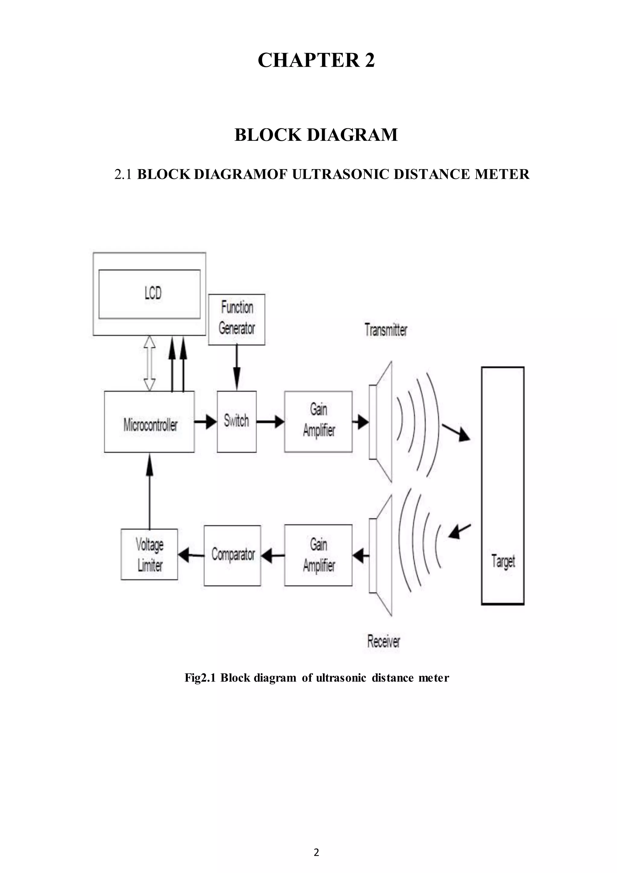
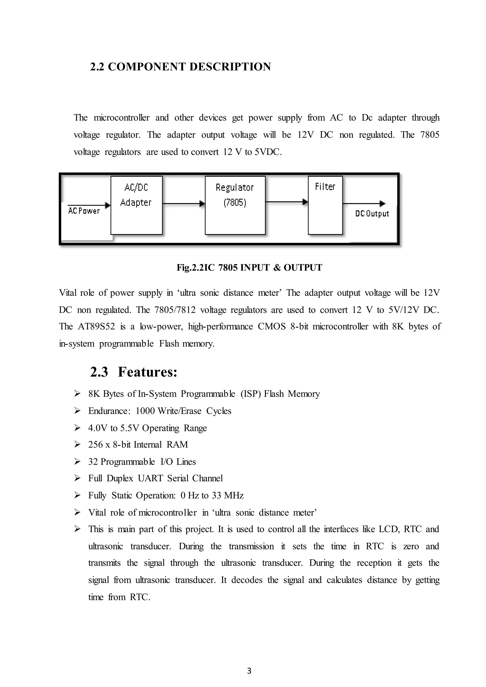
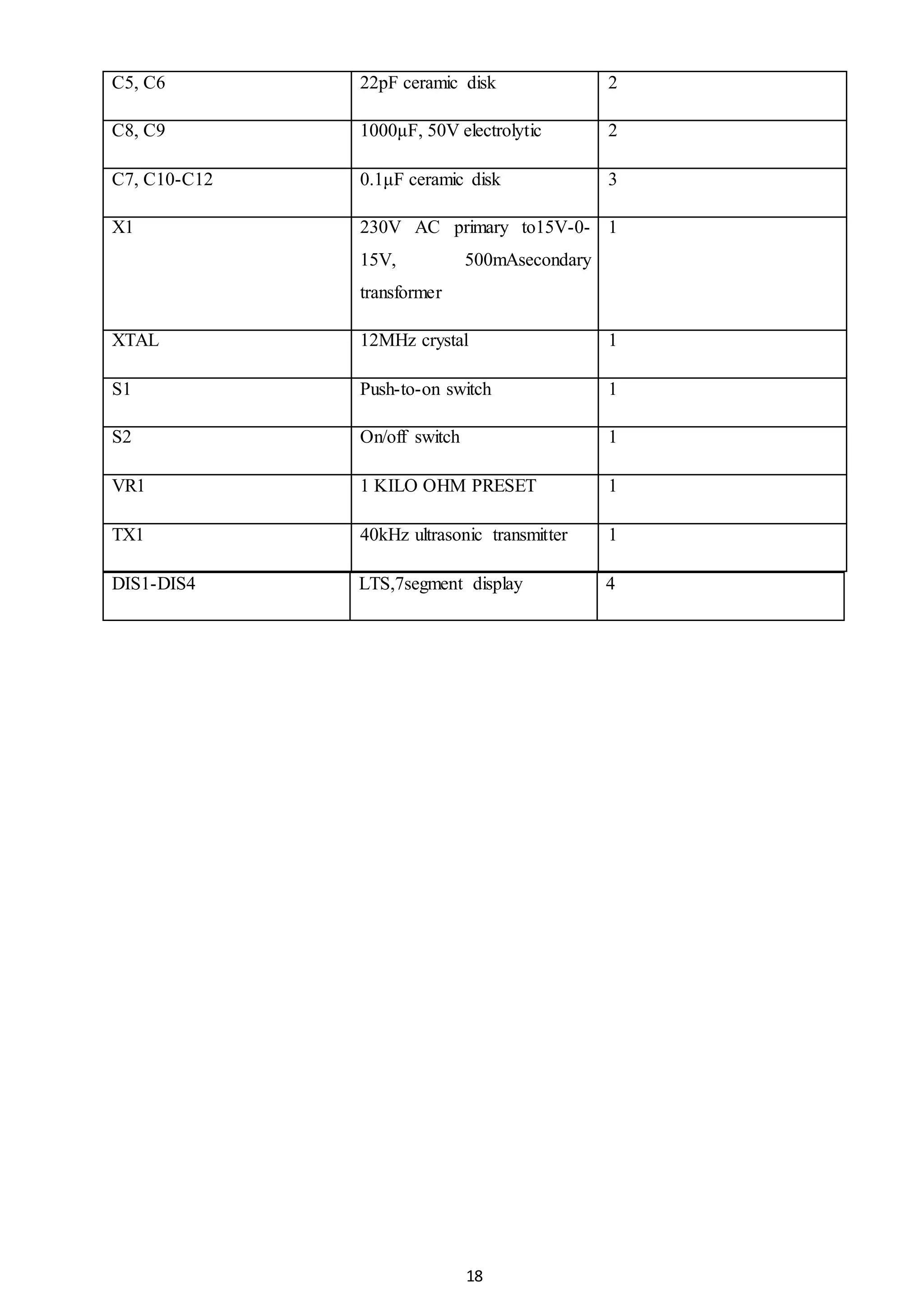
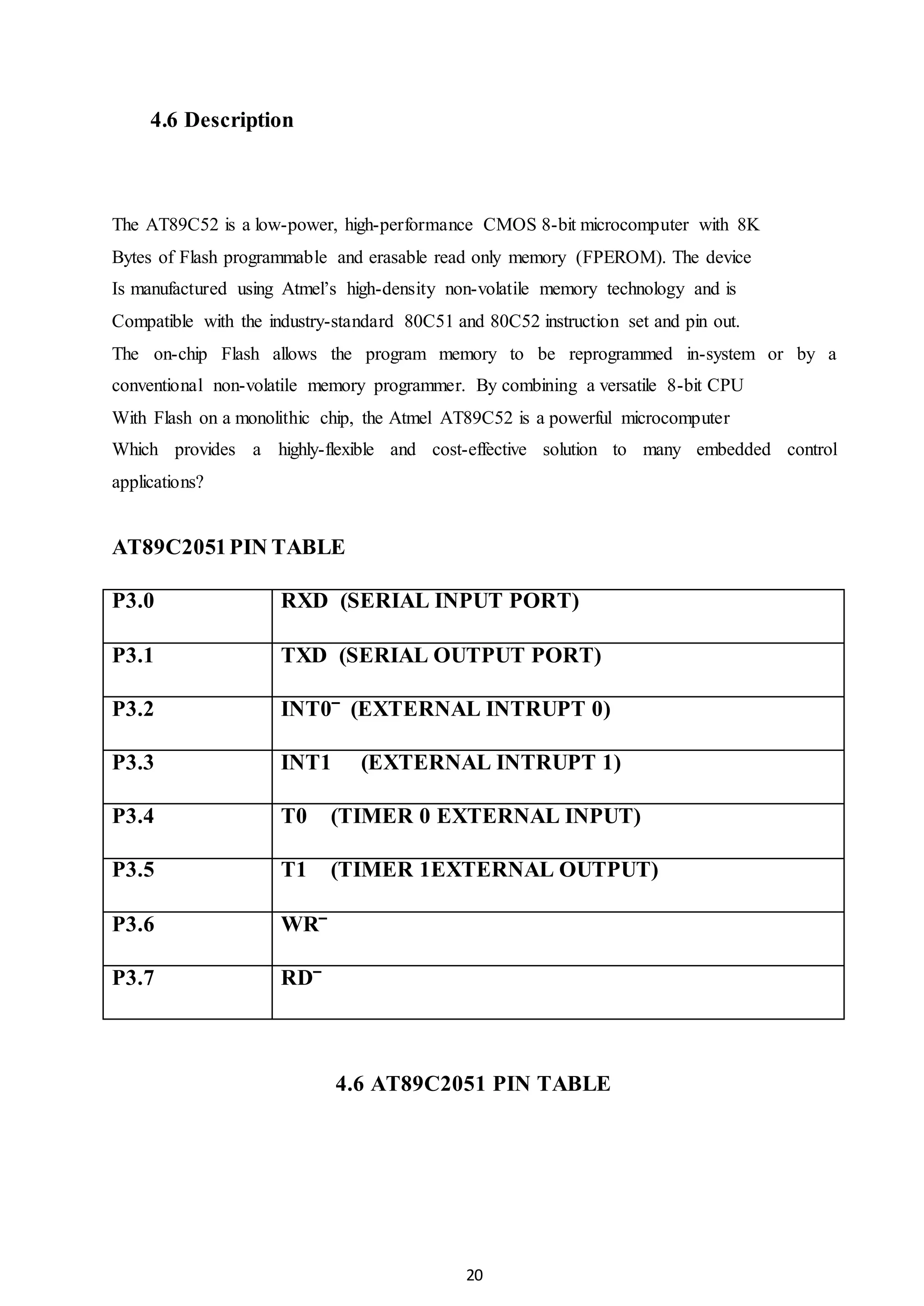
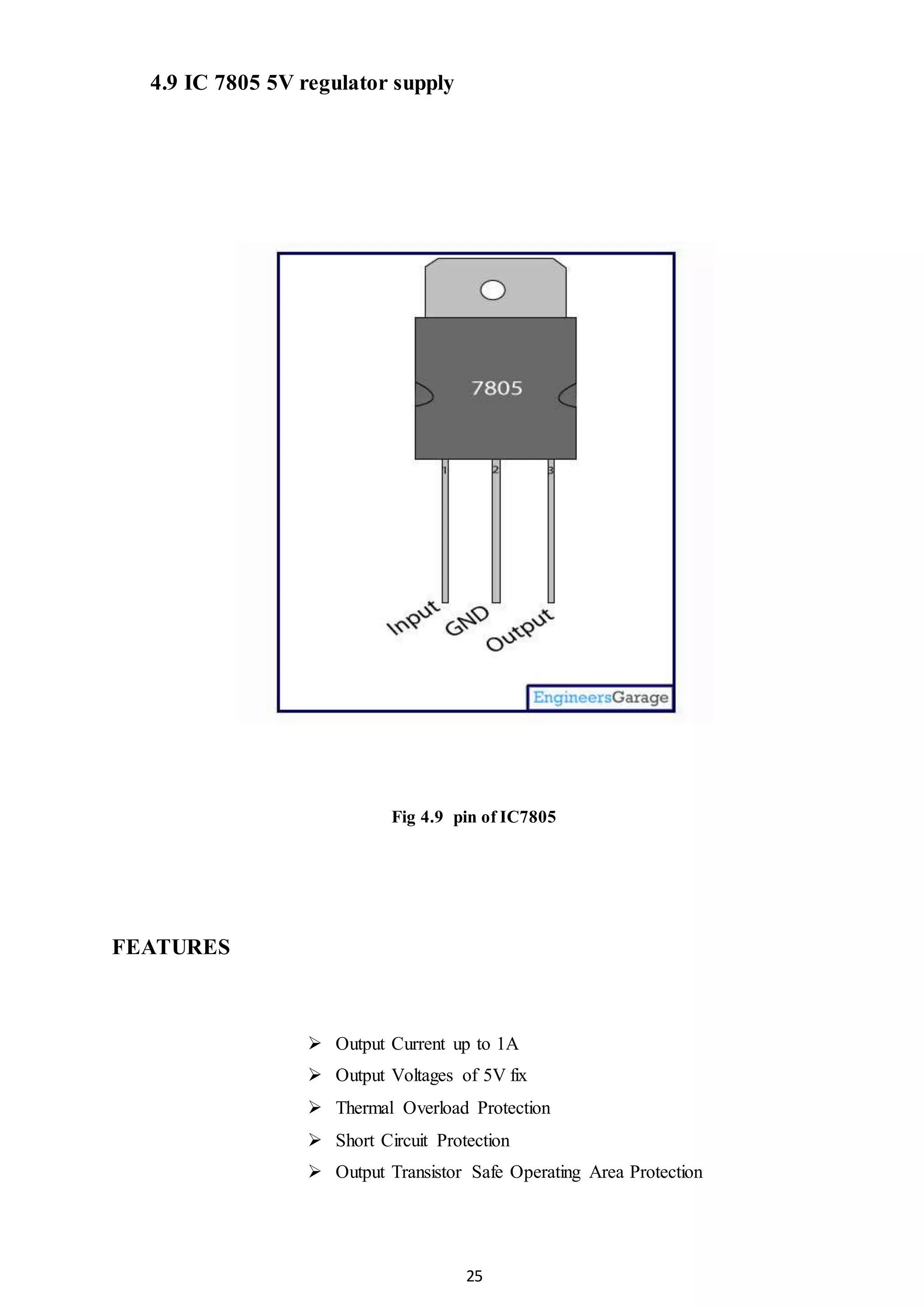
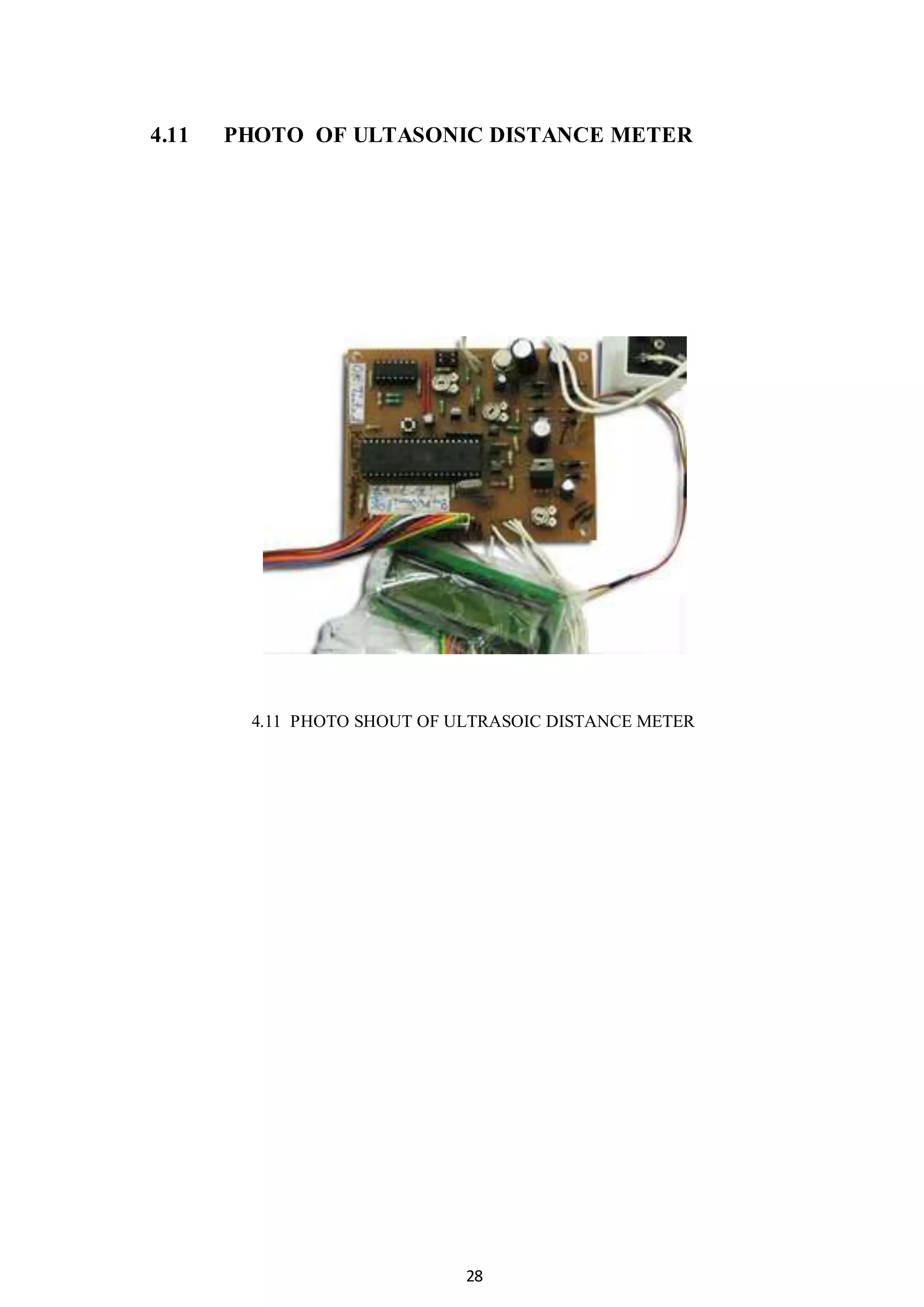
SlideShare a Scribd company logo
1
CHAPTER 1
INTRODUCTION
1.1 INTRODUCTION
During the transmission microcontroller encodes the signal and transmits through the
Ultrasonic transmitter. The Ultrasonic transmitter converts the electrical signal to pulse.
During this time the time set is zero. Ultrasonic transducer emits a burst of 12 pulses at a
frequency, which is roughly identical with resonance frequency of the two
transducers.After the burst has been emitted the unit is switched to reception. The
sensitivity of the receiver is a function of time. When these pulses hits any object they
are reflected back and are received by ultrasonic receiver. The number of clock pulses
counted between onsets of the emission the burst and the sensing of echo is equal to
distance between two objects. The microcontroller calculates distance by using time. The
time taken to detect the target is helpful for finding the distance of the objects. The
measured distance or height is displayed on LCD. The senility of the receiver is a
function of time. When these pulses hits any object they are reflected back and are
received by ultrasonic receiver. The number of clock pulses counted between onsets of
the emission the burst and the sensing of echo is equal to distance between two objects.
2
CHAPTER 2
BLOCK DIAGRAM
2.1 BLOCK DIAGRAMOF ULTRASONIC DISTANCE METER
Fig2.1 Block diagram of ultrasonic distance meter
3
2.2 COMPONENT DESCRIPTION
The microcontroller and other devices get power supply from AC to Dc adapter through
voltage regulator. The adapter output voltage will be 12V DC non regulated. The 7805
voltage regulators are used to convert 12 V to 5VDC.
Fig.2.2IC 7805 INPUT & OUTPUT
Vital role of power supply in ‘ultra sonic distance meter’ The adapter output voltage will be 12V
DC non regulated. The 7805/7812 voltage regulators are used to convert 12 V to 5V/12V DC.
The AT89S52 is a low-power, high-performance CMOS 8-bit microcontroller with 8K bytes of
in-system programmable Flash memory.
2.3 Features:
 8K Bytes of In-System Programmable (ISP) Flash Memory
 Endurance: 1000 Write/Erase Cycles
 4.0V to 5.5V Operating Range
 256 x 8-bit Internal RAM
 32 Programmable I/O Lines
 Full Duplex UART Serial Channel
 Fully Static Operation: 0 Hz to 33 MHz
 Vital role of microcontroller in ‘ultra sonic distance meter’
 This is main part of this project. It is used to control all the interfaces like LCD, RTC and
ultrasonic transducer. During the transmission it sets the time in RTC is zero and
transmits the signal through the ultrasonic transducer. During the reception it gets the
signal from ultrasonic transducer. It decodes the signal and calculates distance by getting
time from RTC.
4
 LCD (LIQUID CRYSTAL DISPLAY)
 LCD’s can add a lot to your application in terms of providing a useful interface for the user,
debugging an application or just giving it a "professional" look.
 The most common type of LCD controller is the Hitatchi 44780 which provides a relatively
simple interface between a processor and an LCD.
 Using this interface is often not attempted by inexperienced designers and programmers because
it is difficult to find good documentation on the interface, initializing the interface can be a
problem and the displays themselves are expensive.
 Vital role of LCD in ‘ultra sonic distance meter’
 LCD has single line display, Two-line display, four line display. Every line has 16
characters. This is used to display the operation of the system in written form.
 Buzzer
 The buzzer subsystem produces a 2 KHz audible tone when powered.
 The buzzer will sound when the signal coming into the driver is high. It must be
connected to a transistor, Darlington or transducer driver subsystem.
 The buzzer is connected between the supply rail (+V) and the input signal. This acts as
load on the driver.
 When the input signal coming into the buzzer subsystem is low, a potential difference
across the buzzer causes current to flow.
 It is this flow of current that causes the buzzer to sound.
 Vital role of Buzzer in ‘ultra sonic distance meter’
 This is used to indicate the extreme condition system.
5
 Features of Ultrasonic distance meter
 Fast & easy access.
 Long distance communication.
 Wireless communication
2.4 Applications
 For scientists.
 For colleges.
 For radar.
6
CHAPTER 3
3.1CIRCUIT DIAGRAM
Fig3.1 circuit diagram
7
3.2 CIRCUIT DISCRIPTION
The circuit of the microcontroller-based distance meter. The 40 kHz pulse bursts from the
microcontroller are amplify by transistor t5. Inverting buff- er cd4049 drives the ultrasonic
sensor used as the transmitter. Three inverters (n1, n2 and n3) are con- netted in parallel to
increase the transmitted power. This inverted out- put is fed to an- other set of three inverters
(n4, n5 and n6). Outputs of both sets of par- allele inverters are applied as a push- pull drive to
the ultrasonic trans- meter.
The positive- going pulse is ap- plied to one of the terminals of the ultrasonic sensor and the
same pulse after 180-degree phase shift is ap- plied to another terminal.
Thus the transmitter power is increased for in- creasing the range. If you want to increase the
range up to 5 metres, use a ferrite-core step- up pulse transformer, which steps-up the transmitter
output to 60v (peak- to-peak). The echo signal received by the receiver sensor after reflections
very weak. It is amplified by quad opera-(a1) is a buffer with unity gain.
The received signal is directly fed to the non-inverting input (pin 3) of a1 and coupled to the
second stage by a 3.3nf (small-value) capacitor. If you use the ubiquitous 0.01µf capacitor for
coupling, there will be enormous hum at the output.
The second stage of the (a1) is a buffer with unity gain. The received signal is directly fed to the
non-inverting input (pin 3) of a1 and coupled to the second stage by a 3.3nf (small-value)
capacitor. If you use the ubiquitous 0.01µf capacitor for coupling, there will be enormous hum at
the output. The second stage of the inverting amplifier uses a 2-mega-ohm resistor for feedback.
The third stage is a precision rectifier amplifier with a gain of 10.The rectifier functions, unlike a
simple diode, even for signal voltage of less than 0.6v.
The output is faltered to accept 40 kHz frequencies and fed to pin 12 of microcontroller
at89c2051, which is an analogue comparator. Pin 13 is the other pin of the comparator used for
level adjustment using preset vr1.
The ultrasonic transducer outputs a beam of sound waves, which has more energy on the main
lobe and less energy. (60 db below the main lobe)Even this low side-lobe signal is directly
picked up by the receiver unit. So you have to space the transmitter and receiver units about 5
cm apart. The two units are fixed by cello tape onto a cardboard, with the analogue circuit at one
end. Microcontroller at89c2051 is at the heart of the circuit.
8
Port-1 pins p1.7 through p1.2, and port-3 pin p3.7 are connected to input pins 1 through 7 of ic2
(ic uln2003), respectively. These pins are pulled up with a 10-kilo-ohm resistor network
rnw1.They drive all the segments of the 7-segment display with the help of inverting buffer ic2.
Port-3 pins p3.0 through p3.3 of the microcontroller are connected to the base of transistors t1
through t4 to provide the supply to displays dis1 through dis4, respectively. Pin p3.0 of
microcontroller ic1 goes low to drive transistor t1 into saturation, which provides supply to the
com- non-anode pin (either pin 3 or 8) of display dis1.
Outputs of both sets of par- allele inverters are applied as a push- pull drive to the ultrasonic
trans- meter. The positive- going pulse is ap- plied to one of the terminals of the ultrasonic
sensor and the same pulse after 180-degree phase shift is ap- plied to another terminal.
Thus the transmitter power is increased for in- creasing the range. If you want to increase the
range up to 5 metres, use a ferrite-core step- up pulse transformer, which steps-up the transmitter
output to 60v (peak- to-peak). The echo signal received by the receiver sensor after reflections
very weak. It is amplified by quad opera-(a1) is a buffer with unity gain.
The received signal is directly fed to the non-inverting input (pin 3) of a1 and coupled to the
second stage by a 3.3nf (small-value) capacitor. If you use the ubiquitous 0.01µf capacitor for
coupling, there will be enormous hum at the output. The second stage of the (a1) is a buffer with
unity gain. The received signal is directly fed to the non-inverting input (pin 3) of a1 and
coupled to the second stage by a 3.3nf (small-value) capacitor.
If you use the ubiquitous 0.01µf capacitor for coupling, there will be enormous hum at the
output.The second stage of the inverting amplifier uses a 2-mega-ohm resistor for feedback. The
third stage is a precision rectifier amplifier with a gain of 10.The rectifier functions, unlike a
simple diode, even for signal voltage of less than 0.6v.The output is faltered to accept 40khz
frequencies and fed to pin 12 of microcontroller at89c2051, which is an analogue
comparator.Pin 13 is the other pin of the comparator used for level adjustment using preset vr1.
The ultrasonic transducer outputs a beam of sound waves, which has more energy on the main
lobe and less energy. (60 db below the main lobe)
9
Even this low side-lobe signal is directly picked up by the receiver unit. So you have to space the
transmitter and receiver units about 5 cm apart.
The two units are fixed by cello tape onto a cardboard, with the analogue circuit at one end.
Microcontroller at89c2051 is at the heart of the circuit. Port-1 pins p1.7 through p1.2, and port-3 pin p3.7
are connected to input pins 1 through 7 of ic2 (ic uln2003), respectively. These pins are pulled up with a
10-kilo-ohm resistor network rnw1. They drive all the segments of the 7-segment display with the help of
inverting buffer ic2. Port-3 pins p3.0 through p3.3 of the microcontroller are connected to the base of
transistors t1 through t4 to provide the supply to displays dis1 through dis4, respectively.
Pin p3.0 of microcontroller ic1 goes low to drive transistor t1 into saturation, which provides supply to
the com- non-anode pin (either pin 3 or 8) of display dis1.
10
CHAPTER 4
THEORY AND APPLICATION
4.1ULTRASOUND THEORY
Ultrasound is a cyclic sound pressure wave with a frequency greater than the upper limit of the
human hearing range.
Ultrasound is thus not separated from "normal" (audible) sound based on differences in physical
properties, only the fact that humans cannot hear it. Although this limit varies from person to
person, it is approximately 20 kilohertz (20,000 hertz) in healthy, young adults. Ultrasound
devices operate with frequencies from 20 kHz up to several gigahertz
Fig 4.1 1PRINCIPLE OF AN ACTIVE SONAR
Fig 4.2 2PRINCIPLE OF FLAW DETECTION WITH ULTRASOUND
11
The results obtained from this work are summarized as follows:
 Noncontact ultrasonic imaging system was developed for the visualization of ultrasonic
waves propagating on opaque media.
 This imaging system provides propagation image, amplitude image, arrival time image,
trajectory image and velocity image.
 By use of this visualization method can produce a series of successive images as an
animation of wave propagation.
 This technique is applicable to non-destructive inspection and materials characterization.
 Ultrasonic sensors (also known as transceivers when they both send and receive) work on
a principle similar to radar or sonar which evaluate attributes of a target by interpreting
the echoes from radio or sound waves respectively.
 Ultrasonic sensors generate high frequency sound waves and evaluate the echo which is
received back by the sensor. Sensors calculate the time interval between sending the
signal and receiving the echo to determine the distance to an object.
 This technology can be used for measuring: wind speed and direction (anemometer),
fullness of a tank and speed through air or water. For measuring speed or direction a
device uses multiple detectors and calculates the speed from the relative distances to
particulates in the air or water.
 To measure the amount of liquid in a tank, the sensor measures the distance to the
surface of the fluid.
 Further applications include: humidifiers, sonar, medical ultrasonography, burglar alarms
and non-destructive testing.
 Systems typically use a transducer which generates sound waves in the ultrasonic range,
above 18,000 hertz, by turning electrical energy into sound, then upon receiving the echo
turn the sound waves into electrical energy which can be measured and displayed.
 An ultrasonic transducer is a device that converts energy into ultrasound, or sound waves
above the normal range of human hearing.
12
 While technically a dog whistle is an ultrasonic transducer that converts mechanical
energy in the form of air pressure into ultrasonic sound waves, the term is more apt to be
used to refer to piezoelectric transducers that convert electrical energy into sound.
Piezoelectric crystals have the property of changing size when a voltage is applied, thus
applying an alternating current (AC) across them
4.2 Applications
In Industries
 Cavitations is probably the most interesting (and potent) effect - the shock waves
generated by tiny implosions of vapour bubbles can be devastating at close range.
 The bubbles are so tiny that they can penetrate even the smallest crevices, making the
process ideal for parts which could not be cleaned by other methods.
 Note also that the process must be well controlled to minimise erosion of the surfaces of
the parts being cleaned.
 The standard test of ultrasonic intensity in a cleaning bath is to immerse a standard foil
strip for a set time, then remove it and count the number of holes!Traditionally the
transducers were fitted around the walls of the cleaning bath, but some modern
equipment uses an external transducer attached to a resonant probe which transmits the
vibrations to the fluid.
 The ultrasonic’s may affect the cleaning process in several ways. Rapid movement in the
fluid can help to de-wet surfaces, overcoming surface tension, and may also help to
dislodge dirt particles and carry them away from the surface.
 Cavitations is probably the most interesting (and potent) effect - the shock waves
generated by tiny implosions of vapour bubbles can be devastating at close range.
 The bubbles are so tiny that they can penetrate even the smallest crevices, making the
process ideal for parts which could not be cleaned by other methods.
 Note also that the process must be well controlled to minimise erosion of the surfaces of
the parts being cleaned.
13
 The standard test of ultrasonic intensity in a cleaning bath is to immerse a standard foil
strip for a set time, then remove it and count the number of holes!
In cleaning
 Cleaning was one of the earliest industrial applications of ultrasonics. Objects to be
cleaned are placed in a bath of fluid which is violently agitated by a number of ultrasonic
transducers.
 The fluid may be water or solvent based, depending on the application.
In cutting
 Imagine a knife which moves itself backwards and forwards in a sawing action, thirty
thousand times a second.
 True the distance moved is very small but the acceleration is so high that nothing can
move with the blade or stick to it. Ultrasonic scalpels are used by surgeons
 where they want to cut without exerting any pressure.
 In industry ultrasonic cutting tools are used for products that are difficult to cut by other
means.
 The heat generated by the ultrasonic vibrations can also be useful.
 Some man-made fabrics are cut and simultaneously sealed using ultrasonic knives
toprevent fraying.
METAL FORMING
 My own experience of power ultrasonic is mainly in this field. CarnaudMetalbox R&D
(now a part of Crown Cork and Seal - the biggest packaging company in the world) and
Loughborough University developed a new aerosol can using a number of novel metal-
forming processes, starting with ultrasonic necking (i.e. reducing the diameter of the can
at one end).
14
 The advantage of using ultrasonic in this case was to minimise friction between the can and
the die, thus reducing the forming force. Without ultrasonics the force was so high that the
can body would buckle and collapse during the necking process.
 With ultrasonic a 30% reduction in can diameter could be achieved in a single operation (in
conventional necking processes the maximum is typically about 5%).
 The ultrasonic were only effective when the vibrations were perpendicular to the surface -
for a cylindrical can this meant developing a round die that would vibrate in the radial
direction. As with other high-power applications, all tooling had to be resonant, so the
desired mode of resonance was a uniform hoop expansion / contraction.
 We quickly found that while it was fairly easy to design a die to resonate in this mode at the
frequency of the ultrasonic equipment, excluding other modes of vibration was a major
challeng
 Another difficulty was that with the whole die expanding and contracting there was no
convenient nodal (stationary) point which could be used for mouning it.
 This was solved by the use of a tubular mounting system which was itself resonant at the
same frequency as the die.
 The ultrasonic forming process went into production making small-diameter aerosol cans in
a UK factory.
 The production line still runs intermittently, making promotional packaging for several
prominent customers. One of its products ("Flexures de Paris" parfumdeospray can) won
silver in the 1997 Metal Packaging Manufacturers Association awards.
METAL WELDING
 Ultrasonic can be used to weld different metals together, without solder and flux or special
preparation.
 The process is different to plastic welding in that the two components are vibrated parallel to the
interface.
 This is a more intuitively logical method of generating friction between them, but frictional
heating is not thought to be the prime mechanism of the process - the temperature needed to melt
(or even soften) most metals would be very difficult to achieve. Instead the mechanism is
15
thought to be diffusion-bonding: atoms of each part diffuse into the other when the two surfaces
are brought together in close contact.
 The ultrasonic’s promotes this close contact by breaking down the surface oxide layers,
allowing the "raw" metals to make contact. The process has some limitations. It is only
suitable for relatively small components (a prime example is welding connectors to car
battery leads) since the power required to weld larger parts would be higher than can
practically supplied by this method.
 Also the process tends to mark and deform the components, since high clamping forces
and sonotrodes with serrated working faces must be used to grip the workpiece firmly.
PLASTIC WELDING
 Plastic welding is used for a huge variety of products ranging from blister packs,
cartons andsmall consumer goods up to car fuel tanks and dashboards.
 It works by generating heat exactly where it is needed - at the interface between the
components to be joined. The
 Components are clamped between a vibrating sonotrode and a fixed mounting.
Strangely, the vibrations are usually applied perpendicular to the contact surface,
although much of this vibration may be converted to in-plane movement.
 This also has the advantage that the clamping pressure will keep the sonotrode in
contact with the component - serrated surfaces are generally not required. Best results
are achieved when the components are clamped close to the interface ("near-field"
welding) but if this is not possible then the process can still work at a distance ("far-
field").
 Staking, or insertion, is a variation of this process in which a metal part (generally a
threaded bush) is driven into a hole in a plastic component, which then solidifies
around it to form a permanent join.
 This is a convenient method of producing strong tapped holes in a plastic part.
16
4.3 CONCLUSION
The integrated analog Comparator A, the 16-bit Timer A with hardware
capture/compareregisters, the Basic Timer1, and the LCD driver peripherals simplify this
ultrasonic distance measurement application design and provide a system-in-a-chip solution. The
average currentconsumed by the application is 1.3 mA during a 15-inch distance measurement.
This includesthe quiescent current of LDO U2, operational amplifier U3, and CMOS hex
inverter U4.Theoperational amplifier alone has a quiescent current of 1 mA and the remainder of
the circuit current consumption is 300 μA. The LED draws 5 mA while it is on. The MSP430
draws an average current of 2.1 μA with the LCD continuously active. This is made possible by
taking advantage of the ultralow-current features of the MSP430. The MSP430 sleeps in LPM3
mostof the time and the CPU resources used by this application are only 5.6%.
17
4.4 COMPONENT LIST
Components Value Quantity
IC1 AT89C52 microcontroller 1
IC2 7812 12V regulator 1
IC3 7805 5V regulator 1
IC4 LM324 quad Amplifier 1
IC5 7815, 15V regulator 1
IC6 7915, -15V regulator 1
IC7 7805, 5V regulator 1
T1-T4 BC557 pnp transistor 4
T5 2N2222 npn transistor 1
D1, D2 & D3-D6 N4007 rectifier diode 4
R1, R2 2-mega-ohm 2
R3 82-kilo-ohm 1
R4, R7-R10 10-kilo-ohm 3
R5 33-kilo-ohm 1
R6 100-kilo-ohm 1
R12- R15 12-kilo-ohm 4
C1, C2 3.3nF ceramic disk 2
R16 220-ohm 1
R11 1-kilo-ohm 1
C3 2.2nF ceramic disk 1
C4 10μF, 16V electrolytic 1
18
DIS1-DIS4 LTS,7segment display 4
C5, C6 22pF ceramic disk 2
C8, C9 1000μF, 50V electrolytic 2
C7, C10-C12 0.1μF ceramic disk 3
X1 230V AC primary to15V-0-
15V, 500mAsecondary
transformer
1
XTAL 12MHz crystal 1
S1 Push-to-on switch 1
S2 On/off switch 1
VR1 1 KILO OHM PRESET 1
TX1 40kHz ultrasonic transmitter 1
19
4.5 BLOCK DIAGRAM OF AT89C2051
20
4.6 Description
The AT89C52 is a low-power, high-performance CMOS 8-bit microcomputer with 8K
Bytes of Flash programmable and erasable read only memory (FPEROM). The device
Is manufactured using Atmel’s high-density non-volatile memory technology and is
Compatible with the industry-standard 80C51 and 80C52 instruction set and pin out.
The on-chip Flash allows the program memory to be reprogrammed in-system or by a
conventional non-volatile memory programmer. By combining a versatile 8-bit CPU
With Flash on a monolithic chip, the Atmel AT89C52 is a powerful microcomputer
Which provides a highly-flexible and cost-effective solution to many embedded control
applications?
AT89C2051PIN TABLE
P3.0 RXD (SERIAL INPUT PORT)
P3.1 TXD (SERIAL OUTPUT PORT)
P3.2 INT0‾ (EXTERNAL INTRUPT 0)
P3.3 INT1 (EXTERNAL INTRUPT 1)
P3.4 T0 (TIMER 0 EXTERNAL INPUT)
P3.5 T1 (TIMER 1EXTERNAL OUTPUT)
P3.6 WR‾
P3.7 RD‾
4.6 AT89C2051 PIN TABLE
21
4.7 PIN DIAGRAM OF AT89C52
.
22
4.7 PIN DISCRIPTION
 XTAL1: Input to the inverting oscillator amplifier.
 XTAL2: Output from the inverting oscillator amplifier.
 Port 0: Port 0 is an 8-bit open drain bidirectional port. As an open drain output port, it
can sink eight LS TTL loads. Port 0 pins that have 1s written to them float, and in that
state will function as high impedance inputs. Port 0 is also the multiplexed low-order
address and data bus during accesses to external memory. In this application it uses
strong internal pull-ups when emitting 1s. Port 0 emits code bytes during program
verification. In this application, external pull-ups are required.
 Port 1: Port 1 is an 8-bit bidirectional I/O port with internal pull-ups. Port 1 pins that
have 1s written to them are pulled high by the internal pull-ups, and in that state can be
used as inputs. As inputs, port 1 pins that are externally being pulled low will source
current because of the internal pull-ups.
 Port 2: Port 2 is an 8-bit bidirectional I/O port with internal pull-ups. Port 2 emits the
high-order address byte during accesses to external memory that use 16-bit addresses. In
this application, it uses the strong internal pull-ups when emitting 1s.
 Port 3: Port 3 is an 8-bit bidirectional I/O port with internal pull-ups. It also serves the
functions of various special features of the 80C51 Family as follows:
 Port Pin Alternate Function
 P3.0 RxD (serial input port)
 P3.1 TxD (serial output port)
 P3.2 INT0 (external interrupt 0)
 P3.3 INT1 (external interrupt 1)
23
 P3.4 T0 (timer 0 external input)
 P3.5 T1 (timer 1 external input)
 P3.6 WR (external data memory write strobe)
 P3.7 RD (external data memory read strobe)
 VCC: Supply voltage
 PSEN:
 Program Store Enable is the read strobe to external program memory. When the
AT89C52 is executing code from external program memory, PSEN is activated twice
each machine cycle, except that two PSEN activations are skipped during each access to
external data memory.
 EA/VPP:
 External Access Enable. EA must be strapped to GND in order to enable the device to
fetch code from external program memory locations starting at 0000H up to FFFFH.
Note, however, that if lock bit 1 is programmed, A will be internally latched on reset. A
should be strapped to VCC for internal program executions. This pin also receives the
12-volt programming enable voltage (VPP) during Flash programming when 12-volt
programming is selected.
24
4.8 PCB LAYOUT
25
4.9 IC 7805 5V regulator supply
Fig 4.9 pin of IC7805
FEATURES
 Output Current up to 1A
 Output Voltages of 5V fix
 Thermal Overload Protection
 Short Circuit Protection
 Output Transistor Safe Operating Area Protection
26
7805 REGULATOR IC DESCRIPTION
 The 7805 voltage regulators employ built-in current limiting, thermal shutdown, and safe-
operating area protection which make them virtually immune to damage from output overloads.
7805 is a three-terminal positive voltage regulator.
 With adequate heat sinking, it can deliver in excess of 0.5A output current. Typical applications
would include local (on-card) regulators which can eliminate the noise and degraded
performance associated with single-point regulation.
 7805 regulator comes from the 78xx family of self-contained fixed linear voltage regulator
integrated circuits. The 78xx family is a very popular choice for many electronic circuits which
require a regulated power supply, due to their ease of use and relative cheapness. When
specifying individual ICs within this family, the xx is replaced with a two-digit number, which
indicates the output voltage the particular device is designed to provide (for example, the 7805
voltage regulator has a 5 volt output, while the 7812 produces 12 volts). The 78xx line is positive
voltage regulators, meaning that they are designed to produce a voltage that is positive relative to
a common ground. There is a related line of 79xx devices which are complementary negative
voltage regulators. 78xx and 79xx ICs can be used in combination to provide both positive and
negative supply voltages in the same circuit, if necessary.
 7805 ICs have three terminals and are most commonly found in the TO220 form factor, although
smaller surface-mount and larger TO3 packages are also available from some manufacturers.
These devices typically support an input voltage which can be anywhere from a couple of volts
over the intended output voltage, up to a maximum of 35 or 40 volts, and can typically provide
up to around 1 or 1.5 amps of current (though smaller or larger packages may have a lower or
higher current rating).
 The 7805 series has several key advantages over many other voltage regulator circuits which
have resulted in its popularity:
 7805 series ICs do not require any additional components to provide a constant, regulated source
of power, making them easy to use, as well as economical, and also efficient uses of circuit board
real estate. By contrast, most other voltage regulators require several additional components to
set the output voltage level, or to assist in the regulation process. Some other designs (such as a
switching power supply) can require not only a large number of components but also substantial
engineering expertise to implement correctly as well.
 7805 series ICs have built-in protection against a circuit drawing too much power. They also
have protection against overheating and short-circuits, making them quite robust in most
applications. In some cases, the current-limiting features of the 7805 devices can provide
protection not only for the 7805 itself, but also for other parts of the circuit it is used in,
preventing other components from being damaged as well.
27
4.10 CD4049 Hex Non-Inverting Buffer
General Description
The CD4049UBC and CD4050BC hex buffers are monolithic complementary MOS (CMOS)
integrated circuits constructed with N- and P-channel enhancement mode transistors.
 These devices feature logic level conversion using only one supply voltage (VDD).
 The input signal high level (VIH) can exceed the VDD supply voltage when these
devices are used for logic level conversions.
 These devices are intended for use as hex buffers, CMOS to DTL/ TTL converters, or as
CMOS current drivers, and at VDD = 5.0V, they can drive directly two DTL/TTL loads
over the full operating temperature range.
 Features
 Wide supply voltage range: 3.0V to 15V
 Direct drive to 2 TTL loads at 5.0V over full temperature range High source and sink
current capability Special input protection permits input voltages greater than VDD
28
4.11 PHOTO OF ULTASONIC DISTANCE METER
4.11 PHOTO SHOUT OF ULTRASOIC DISTANCE METER
29
4.12 DESCRIPTION/ORDERING INFORMATION
 These devices consist of four independent high-gain frequency-compensated operational
amplifiers that are designed specifically to operate from a single supply over a wide
range of voltages.
 Operation from split supplies also is possible if the difference between the two supplies is
3 V to 32 V (3 V to 26 V for the LM2902), and VCC is at least-1.5 V more positive than
the input common-mode Applications include transducer amplifiers, dc amplification
blocks, and all the conventional operational-amplifier circuits that now can be more
easily implemented in single-supply-voltage systems.
 For example, the LM124 can be operated directly from the standard 5-V supply that is
used in digital systems and provides the required interface electronics, without requiring
additional ±15-V supplies.
 Similarly, transistors t2 through t4 provide anode currents to the other three 7-segment
displays. Microcontroller ic1 provides the segment data and display-enable sig- nil
simultaneously in time-division multiplexed mode for displaying a particular number on
the 7-segment display unit.
 Segment data and display-enable pulse for the display are refreshed every 5 ms. Thus the
display appears to be continuous, even though the individual lads used in it light up one
by one.
 Using switch s1 you can manually reset the microcontroller, while the power- on reset
signal for the microcontroller is derived from the combination of capacitor c4 and re-
sistor r8.
 A 12MHz crystal is used to generate the basic clock frequency for the microcontroller.
Resistor r16 connected to pin 5 of dis2 enables the decimal point.
 This status is sensed by the mi- controller as programmed. When port-3 pin p3.6 goes
high, we know that the echo signal has arrived; the timer is read and the 16-bit number is
divided by twice the velocity of sound and then converted into decimal format as a 4-
digit number.
30
REFERENCES:
 The 8051 Microcontroller And Embedded Systems, Muhammad Ali Mazidi, Janice Gillis
pieMazidi
 "8051-Basic Microcontrollers" by Jan Axelson 1994
 "RS232 Tutorial on Data Interface and cables". ARC Electronics. 2010.
http://www.arcelect.com/rs232.htm.
 http://parts.digikey.com/1/parts/678453-lcd-module-16x4-supertwist-w-led-mdls-16465-
ss-lv-g-led-04-g.html
 http://www.computer-engineering.org/ps2keyboard
 http://www.engineersgarage.com/electronic-components
 Rusty, George (July 2, 2002). "Remembering the PROM knights of Intel". EE Times.
 http://www.eetimes.com/issue/fp/showArticle.jhtml;?articleID=18307418

More Related Content

What's hot

Distance Measurement Using Ultrasonic Sensor and Nodemcu
Distance Measurement Using Ultrasonic Sensor and NodemcuDistance Measurement Using Ultrasonic Sensor and Nodemcu
Distance Measurement Using Ultrasonic Sensor and Nodemcu
IRJET Journal
 
HC-SR04 Ultrasonic sensor with Arduino
HC-SR04 Ultrasonic sensor with ArduinoHC-SR04 Ultrasonic sensor with Arduino
HC-SR04 Ultrasonic sensor with Arduino
yeokm1
 
Ultrasonic sensor
Ultrasonic sensorUltrasonic sensor
Ultrasonic sensor
Adarsh Raj
 
Ultrasonic Sensor
Ultrasonic SensorUltrasonic Sensor
Ultrasonic Sensor
Jeran Rai
 
Arduino Radar System
Arduino Radar SystemArduino Radar System
Arduino Radar System
Akram AlSafadi
 
PROJECT REPORT ON Home automation using by Bluetooth
 PROJECT REPORT ON Home automation using by Bluetooth PROJECT REPORT ON Home automation using by Bluetooth
PROJECT REPORT ON Home automation using by Bluetooth
Aakashkumar276
 
Distance Measurement by Ultrasonic Sensor
Distance Measurement by Ultrasonic SensorDistance Measurement by Ultrasonic Sensor
Distance Measurement by Ultrasonic Sensor
Edgefxkits & Solutions
 
Proximity sensor
Proximity sensorProximity sensor
Proximity sensor
shweta jindal
 
Obstacle detection using ultra sonic sensor
Obstacle detection using ultra sonic sensorObstacle detection using ultra sonic sensor
Obstacle detection using ultra sonic sensor
satyashanker
 
Antenna presentation PPT
Antenna presentation PPTAntenna presentation PPT
Antenna presentation PPT
Sachin Kadam
 
Project report on home automation using Arduino
Project report on home automation using Arduino Project report on home automation using Arduino
Project report on home automation using Arduino
AMIT SANPUI
 
Missile detection and automatic destroy system
Missile detection and automatic destroy system Missile detection and automatic destroy system
Missile detection and automatic destroy system
LokeshLavakusha
 
Obstacle Avoidance ROBOT using ARDUINO
Obstacle Avoidance ROBOT using ARDUINOObstacle Avoidance ROBOT using ARDUINO
Obstacle Avoidance ROBOT using ARDUINO
jovin Richard
 
Radar system using arduino
Radar system using arduinoRadar system using arduino
Radar system using arduino
Faisal Kabir
 
Arduino based health monitoring system
Arduino based health monitoring systemArduino based health monitoring system
Arduino based health monitoring system
Yousuf Shaikh
 
Radar Using Arduino
Radar Using ArduinoRadar Using Arduino
Radar Using Arduino
Golu Jain
 
arduino based radar system
arduino based radar system arduino based radar system
arduino based radar system
akshay1234kumar
 
RADAR SYSTEM
RADAR SYSTEMRADAR SYSTEM
RADAR SYSTEM
VikashKumar1509
 
Ultrasonic radar mini project
Ultrasonic radar  mini projectUltrasonic radar  mini project
Ultrasonic radar mini project
vishnuchiluka
 
waveguides-ppt
waveguides-pptwaveguides-ppt
waveguides-ppt
ATTO RATHORE
 

What's hot (20)

Distance Measurement Using Ultrasonic Sensor and Nodemcu
Distance Measurement Using Ultrasonic Sensor and NodemcuDistance Measurement Using Ultrasonic Sensor and Nodemcu
Distance Measurement Using Ultrasonic Sensor and Nodemcu
 
HC-SR04 Ultrasonic sensor with Arduino
HC-SR04 Ultrasonic sensor with ArduinoHC-SR04 Ultrasonic sensor with Arduino
HC-SR04 Ultrasonic sensor with Arduino
 
Ultrasonic sensor
Ultrasonic sensorUltrasonic sensor
Ultrasonic sensor
 
Ultrasonic Sensor
Ultrasonic SensorUltrasonic Sensor
Ultrasonic Sensor
 
Arduino Radar System
Arduino Radar SystemArduino Radar System
Arduino Radar System
 
PROJECT REPORT ON Home automation using by Bluetooth
 PROJECT REPORT ON Home automation using by Bluetooth PROJECT REPORT ON Home automation using by Bluetooth
PROJECT REPORT ON Home automation using by Bluetooth
 
Distance Measurement by Ultrasonic Sensor
Distance Measurement by Ultrasonic SensorDistance Measurement by Ultrasonic Sensor
Distance Measurement by Ultrasonic Sensor
 
Proximity sensor
Proximity sensorProximity sensor
Proximity sensor
 
Obstacle detection using ultra sonic sensor
Obstacle detection using ultra sonic sensorObstacle detection using ultra sonic sensor
Obstacle detection using ultra sonic sensor
 
Antenna presentation PPT
Antenna presentation PPTAntenna presentation PPT
Antenna presentation PPT
 
Project report on home automation using Arduino
Project report on home automation using Arduino Project report on home automation using Arduino
Project report on home automation using Arduino
 
Missile detection and automatic destroy system
Missile detection and automatic destroy system Missile detection and automatic destroy system
Missile detection and automatic destroy system
 
Obstacle Avoidance ROBOT using ARDUINO
Obstacle Avoidance ROBOT using ARDUINOObstacle Avoidance ROBOT using ARDUINO
Obstacle Avoidance ROBOT using ARDUINO
 
Radar system using arduino
Radar system using arduinoRadar system using arduino
Radar system using arduino
 
Arduino based health monitoring system
Arduino based health monitoring systemArduino based health monitoring system
Arduino based health monitoring system
 
Radar Using Arduino
Radar Using ArduinoRadar Using Arduino
Radar Using Arduino
 
arduino based radar system
arduino based radar system arduino based radar system
arduino based radar system
 
RADAR SYSTEM
RADAR SYSTEMRADAR SYSTEM
RADAR SYSTEM
 
Ultrasonic radar mini project
Ultrasonic radar  mini projectUltrasonic radar  mini project
Ultrasonic radar mini project
 
waveguides-ppt
waveguides-pptwaveguides-ppt
waveguides-ppt
 

Viewers also liked

Ultrasonic-based distance measurement device
Ultrasonic-based distance measurement deviceUltrasonic-based distance measurement device
Ultrasonic-based distance measurement device
Mrinal Sharma
 
ULTRASONIC
ULTRASONICULTRASONIC
ULTRASONIC
praeye
 
Ultrasonic testing
Ultrasonic testingUltrasonic testing
Ultrasonic testingArun Yadav
 
Advance shoes for blind people
Advance shoes for blind peopleAdvance shoes for blind people
Advance shoes for blind people
Utsav Trivedi
 
Ultrasonic Obstacle Avoidance and Auto Brake Car System
Ultrasonic Obstacle Avoidance and Auto Brake Car System Ultrasonic Obstacle Avoidance and Auto Brake Car System
Ultrasonic Obstacle Avoidance and Auto Brake Car System
Mahmoud Kharsa
 

Viewers also liked (9)

Ultrasonic-based distance measurement device
Ultrasonic-based distance measurement deviceUltrasonic-based distance measurement device
Ultrasonic-based distance measurement device
 
Ultrasonic range finder
Ultrasonic range finderUltrasonic range finder
Ultrasonic range finder
 
Contents
ContentsContents
Contents
 
4th-Yr-PROJECT-REPORT
4th-Yr-PROJECT-REPORT4th-Yr-PROJECT-REPORT
4th-Yr-PROJECT-REPORT
 
Ultrasonic_Based_Security_System
Ultrasonic_Based_Security_SystemUltrasonic_Based_Security_System
Ultrasonic_Based_Security_System
 
ULTRASONIC
ULTRASONICULTRASONIC
ULTRASONIC
 
Ultrasonic testing
Ultrasonic testingUltrasonic testing
Ultrasonic testing
 
Advance shoes for blind people
Advance shoes for blind peopleAdvance shoes for blind people
Advance shoes for blind people
 
Ultrasonic Obstacle Avoidance and Auto Brake Car System
Ultrasonic Obstacle Avoidance and Auto Brake Car System Ultrasonic Obstacle Avoidance and Auto Brake Car System
Ultrasonic Obstacle Avoidance and Auto Brake Car System
 

Similar to A report on ultrasonic distance measurement

Oscillator
OscillatorOscillator
Oscillator
SedhuMadhavan7
 
EMI Unit II
EMI Unit IIEMI Unit II
EMI Unit II
GVNSK Sravya
 
Emi unit iii ppt
Emi unit iii pptEmi unit iii ppt
Emi unit iii ppt
SIVA NAGENDRA REDDY
 
Tv remote jammer
Tv remote jammerTv remote jammer
Tv remote jammer
Mayuri Chaudhari
 
TV Remote Jammer
TV Remote JammerTV Remote Jammer
TV Remote Jammer
Ashwini Barhate
 
4_INFRARED REMOTE USED FOR 8
4_INFRARED REMOTE USED FOR 84_INFRARED REMOTE USED FOR 8
4_INFRARED REMOTE USED FOR 8SURAJ MAHAPATRA
 
EMI unit-2 signal generators and signal analyzers
EMI unit-2 signal generators and signal analyzersEMI unit-2 signal generators and signal analyzers
EMI unit-2 signal generators and signal analyzers
GopalakrishnaU
 
EMI unit-2 signal generators and signal analyzers
EMI unit-2  signal generators and signal analyzersEMI unit-2  signal generators and signal analyzers
EMI unit-2 signal generators and signal analyzers
GopalakrishnaU
 
Oscillator
OscillatorOscillator
Oscillator
Ankit Dubey
 
Unit 3 betl 305
Unit 3 betl 305Unit 3 betl 305
Unit 3 betl 305
Prashant Kumar
 
Design of 16 Channel R.F. Mixer
Design of 16 Channel R.F. MixerDesign of 16 Channel R.F. Mixer
Design of 16 Channel R.F. Mixer
IOSR Journals
 
Unit 3 betl 305
Unit 3 betl 305Unit 3 betl 305
Unit 3 betl 305
Prashant Kumar
 
Frequency modulation and its circuits
Frequency modulation and its circuitsFrequency modulation and its circuits
Frequency modulation and its circuits
Barira Khan
 
DESIGN AND IMPLEMENTATION A BPSK MODEM AND BER MEASUREMENT IN AWGN CHANNEL
DESIGN AND IMPLEMENTATION A BPSK MODEM AND BER MEASUREMENT IN AWGN CHANNELDESIGN AND IMPLEMENTATION A BPSK MODEM AND BER MEASUREMENT IN AWGN CHANNEL
DESIGN AND IMPLEMENTATION A BPSK MODEM AND BER MEASUREMENT IN AWGN CHANNEL
Mohammad Liton Hossain
 
Design and Implementation a BPSK Modem and BER Measurement in AWGN Channel
Design and Implementation a BPSK Modem and BER Measurement in AWGN ChannelDesign and Implementation a BPSK Modem and BER Measurement in AWGN Channel
Design and Implementation a BPSK Modem and BER Measurement in AWGN Channel
IJSRP Journal
 
Transistor Amplifire.pptx
Transistor Amplifire.pptxTransistor Amplifire.pptx
Transistor Amplifire.pptx
ProfVilasShamraoPati
 
Airport servilanc radar system Asr 8 usful presentation
Airport servilanc radar system Asr 8 usful presentationAirport servilanc radar system Asr 8 usful presentation
Airport servilanc radar system Asr 8 usful presentation
FaraidonSafi
 
Radio Conformance Test
Radio Conformance TestRadio Conformance Test
Radio Conformance Test
Sukhvinder Singh Malik
 

Similar to A report on ultrasonic distance measurement (20)

Oscillator
OscillatorOscillator
Oscillator
 
EMI Unit II
EMI Unit IIEMI Unit II
EMI Unit II
 
Emi unit iii ppt
Emi unit iii pptEmi unit iii ppt
Emi unit iii ppt
 
Vhf receiver 6m
Vhf receiver 6mVhf receiver 6m
Vhf receiver 6m
 
Tv remote jammer
Tv remote jammerTv remote jammer
Tv remote jammer
 
TV Remote Jammer
TV Remote JammerTV Remote Jammer
TV Remote Jammer
 
4_INFRARED REMOTE USED FOR 8
4_INFRARED REMOTE USED FOR 84_INFRARED REMOTE USED FOR 8
4_INFRARED REMOTE USED FOR 8
 
EMI unit-2 signal generators and signal analyzers
EMI unit-2 signal generators and signal analyzersEMI unit-2 signal generators and signal analyzers
EMI unit-2 signal generators and signal analyzers
 
EMI unit-2 signal generators and signal analyzers
EMI unit-2  signal generators and signal analyzersEMI unit-2  signal generators and signal analyzers
EMI unit-2 signal generators and signal analyzers
 
Oscillator
OscillatorOscillator
Oscillator
 
Unit 3 betl 305
Unit 3 betl 305Unit 3 betl 305
Unit 3 betl 305
 
Report on Mobile Bug
Report on Mobile BugReport on Mobile Bug
Report on Mobile Bug
 
Design of 16 Channel R.F. Mixer
Design of 16 Channel R.F. MixerDesign of 16 Channel R.F. Mixer
Design of 16 Channel R.F. Mixer
 
Unit 3 betl 305
Unit 3 betl 305Unit 3 betl 305
Unit 3 betl 305
 
Frequency modulation and its circuits
Frequency modulation and its circuitsFrequency modulation and its circuits
Frequency modulation and its circuits
 
DESIGN AND IMPLEMENTATION A BPSK MODEM AND BER MEASUREMENT IN AWGN CHANNEL
DESIGN AND IMPLEMENTATION A BPSK MODEM AND BER MEASUREMENT IN AWGN CHANNELDESIGN AND IMPLEMENTATION A BPSK MODEM AND BER MEASUREMENT IN AWGN CHANNEL
DESIGN AND IMPLEMENTATION A BPSK MODEM AND BER MEASUREMENT IN AWGN CHANNEL
 
Design and Implementation a BPSK Modem and BER Measurement in AWGN Channel
Design and Implementation a BPSK Modem and BER Measurement in AWGN ChannelDesign and Implementation a BPSK Modem and BER Measurement in AWGN Channel
Design and Implementation a BPSK Modem and BER Measurement in AWGN Channel
 
Transistor Amplifire.pptx
Transistor Amplifire.pptxTransistor Amplifire.pptx
Transistor Amplifire.pptx
 
Airport servilanc radar system Asr 8 usful presentation
Airport servilanc radar system Asr 8 usful presentationAirport servilanc radar system Asr 8 usful presentation
Airport servilanc radar system Asr 8 usful presentation
 
Radio Conformance Test
Radio Conformance TestRadio Conformance Test
Radio Conformance Test
 

More from itfakash

SEGWAY
SEGWAY SEGWAY
SEGWAY
itfakash
 
KASHUP Wheels - A hybrid segway Report
KASHUP Wheels - A hybrid segway ReportKASHUP Wheels - A hybrid segway Report
KASHUP Wheels - A hybrid segway Report
itfakash
 
Segway self balancing scooter
Segway self balancing scooterSegway self balancing scooter
Segway self balancing scooter
itfakash
 
A report on Rf controlled car
A report on Rf controlled car A report on Rf controlled car
A report on Rf controlled car
itfakash
 
A report on Antibiotics
A report on AntibioticsA report on Antibiotics
A report on Antibiotics
itfakash
 
Substations
SubstationsSubstations
Substations
itfakash
 

More from itfakash (6)

SEGWAY
SEGWAY SEGWAY
SEGWAY
 
KASHUP Wheels - A hybrid segway Report
KASHUP Wheels - A hybrid segway ReportKASHUP Wheels - A hybrid segway Report
KASHUP Wheels - A hybrid segway Report
 
Segway self balancing scooter
Segway self balancing scooterSegway self balancing scooter
Segway self balancing scooter
 
A report on Rf controlled car
A report on Rf controlled car A report on Rf controlled car
A report on Rf controlled car
 
A report on Antibiotics
A report on AntibioticsA report on Antibiotics
A report on Antibiotics
 
Substations
SubstationsSubstations
Substations
 

Recently uploaded

DESIGN A COTTON SEED SEPARATION MACHINE.docx
DESIGN A COTTON SEED SEPARATION MACHINE.docxDESIGN A COTTON SEED SEPARATION MACHINE.docx
DESIGN A COTTON SEED SEPARATION MACHINE.docx
FluxPrime1
 
Governing Equations for Fundamental Aerodynamics_Anderson2010.pdf
Governing Equations for Fundamental Aerodynamics_Anderson2010.pdfGoverning Equations for Fundamental Aerodynamics_Anderson2010.pdf
Governing Equations for Fundamental Aerodynamics_Anderson2010.pdf
WENKENLI1
 
weather web application report.pdf
weather web application report.pdfweather web application report.pdf
weather web application report.pdf
Pratik Pawar
 
Pile Foundation by Venkatesh Taduvai (Sub Geotechnical Engineering II)-conver...
Pile Foundation by Venkatesh Taduvai (Sub Geotechnical Engineering II)-conver...Pile Foundation by Venkatesh Taduvai (Sub Geotechnical Engineering II)-conver...
Pile Foundation by Venkatesh Taduvai (Sub Geotechnical Engineering II)-conver...
AJAYKUMARPUND1
 
ASME IX(9) 2007 Full Version .pdf
ASME IX(9)  2007 Full Version       .pdfASME IX(9)  2007 Full Version       .pdf
ASME IX(9) 2007 Full Version .pdf
AhmedHussein950959
 
J.Yang, ICLR 2024, MLILAB, KAIST AI.pdf
J.Yang,  ICLR 2024, MLILAB, KAIST AI.pdfJ.Yang,  ICLR 2024, MLILAB, KAIST AI.pdf
J.Yang, ICLR 2024, MLILAB, KAIST AI.pdf
MLILAB
 
Architectural Portfolio Sean Lockwood
Architectural Portfolio Sean LockwoodArchitectural Portfolio Sean Lockwood
Architectural Portfolio Sean Lockwood
seandesed
 
Hierarchical Digital Twin of a Naval Power System
Hierarchical Digital Twin of a Naval Power SystemHierarchical Digital Twin of a Naval Power System
Hierarchical Digital Twin of a Naval Power System
Kerry Sado
 
Cosmetic shop management system project report.pdf
Cosmetic shop management system project report.pdfCosmetic shop management system project report.pdf
Cosmetic shop management system project report.pdf
Kamal Acharya
 
Student information management system project report ii.pdf
Student information management system project report ii.pdfStudent information management system project report ii.pdf
Student information management system project report ii.pdf
Kamal Acharya
 
ethical hacking in wireless-hacking1.ppt
ethical hacking in wireless-hacking1.pptethical hacking in wireless-hacking1.ppt
ethical hacking in wireless-hacking1.ppt
Jayaprasanna4
 
English lab ppt no titlespecENG PPTt.pdf
English lab ppt no titlespecENG PPTt.pdfEnglish lab ppt no titlespecENG PPTt.pdf
English lab ppt no titlespecENG PPTt.pdf
BrazilAccount1
 
Industrial Training at Shahjalal Fertilizer Company Limited (SFCL)
Industrial Training at Shahjalal Fertilizer Company Limited (SFCL)Industrial Training at Shahjalal Fertilizer Company Limited (SFCL)
Industrial Training at Shahjalal Fertilizer Company Limited (SFCL)
MdTanvirMahtab2
 
The role of big data in decision making.
The role of big data in decision making.The role of big data in decision making.
The role of big data in decision making.
ankuprajapati0525
 
一比一原版(SFU毕业证)西蒙菲莎大学毕业证成绩单如何办理
一比一原版(SFU毕业证)西蒙菲莎大学毕业证成绩单如何办理一比一原版(SFU毕业证)西蒙菲莎大学毕业证成绩单如何办理
一比一原版(SFU毕业证)西蒙菲莎大学毕业证成绩单如何办理
bakpo1
 
H.Seo, ICLR 2024, MLILAB, KAIST AI.pdf
H.Seo,  ICLR 2024, MLILAB,  KAIST AI.pdfH.Seo,  ICLR 2024, MLILAB,  KAIST AI.pdf
H.Seo, ICLR 2024, MLILAB, KAIST AI.pdf
MLILAB
 
space technology lecture notes on satellite
space technology lecture notes on satellitespace technology lecture notes on satellite
space technology lecture notes on satellite
ongomchris
 
power quality voltage fluctuation UNIT - I.pptx
power quality voltage fluctuation UNIT - I.pptxpower quality voltage fluctuation UNIT - I.pptx
power quality voltage fluctuation UNIT - I.pptx
ViniHema
 
Gen AI Study Jams _ For the GDSC Leads in India.pdf
Gen AI Study Jams _ For the GDSC Leads in India.pdfGen AI Study Jams _ For the GDSC Leads in India.pdf
Gen AI Study Jams _ For the GDSC Leads in India.pdf
gdsczhcet
 
block diagram and signal flow graph representation
block diagram and signal flow graph representationblock diagram and signal flow graph representation
block diagram and signal flow graph representation
Divya Somashekar
 

Recently uploaded (20)

DESIGN A COTTON SEED SEPARATION MACHINE.docx
DESIGN A COTTON SEED SEPARATION MACHINE.docxDESIGN A COTTON SEED SEPARATION MACHINE.docx
DESIGN A COTTON SEED SEPARATION MACHINE.docx
 
Governing Equations for Fundamental Aerodynamics_Anderson2010.pdf
Governing Equations for Fundamental Aerodynamics_Anderson2010.pdfGoverning Equations for Fundamental Aerodynamics_Anderson2010.pdf
Governing Equations for Fundamental Aerodynamics_Anderson2010.pdf
 
weather web application report.pdf
weather web application report.pdfweather web application report.pdf
weather web application report.pdf
 
Pile Foundation by Venkatesh Taduvai (Sub Geotechnical Engineering II)-conver...
Pile Foundation by Venkatesh Taduvai (Sub Geotechnical Engineering II)-conver...Pile Foundation by Venkatesh Taduvai (Sub Geotechnical Engineering II)-conver...
Pile Foundation by Venkatesh Taduvai (Sub Geotechnical Engineering II)-conver...
 
ASME IX(9) 2007 Full Version .pdf
ASME IX(9)  2007 Full Version       .pdfASME IX(9)  2007 Full Version       .pdf
ASME IX(9) 2007 Full Version .pdf
 
J.Yang, ICLR 2024, MLILAB, KAIST AI.pdf
J.Yang,  ICLR 2024, MLILAB, KAIST AI.pdfJ.Yang,  ICLR 2024, MLILAB, KAIST AI.pdf
J.Yang, ICLR 2024, MLILAB, KAIST AI.pdf
 
Architectural Portfolio Sean Lockwood
Architectural Portfolio Sean LockwoodArchitectural Portfolio Sean Lockwood
Architectural Portfolio Sean Lockwood
 
Hierarchical Digital Twin of a Naval Power System
Hierarchical Digital Twin of a Naval Power SystemHierarchical Digital Twin of a Naval Power System
Hierarchical Digital Twin of a Naval Power System
 
Cosmetic shop management system project report.pdf
Cosmetic shop management system project report.pdfCosmetic shop management system project report.pdf
Cosmetic shop management system project report.pdf
 
Student information management system project report ii.pdf
Student information management system project report ii.pdfStudent information management system project report ii.pdf
Student information management system project report ii.pdf
 
ethical hacking in wireless-hacking1.ppt
ethical hacking in wireless-hacking1.pptethical hacking in wireless-hacking1.ppt
ethical hacking in wireless-hacking1.ppt
 
English lab ppt no titlespecENG PPTt.pdf
English lab ppt no titlespecENG PPTt.pdfEnglish lab ppt no titlespecENG PPTt.pdf
English lab ppt no titlespecENG PPTt.pdf
 
Industrial Training at Shahjalal Fertilizer Company Limited (SFCL)
Industrial Training at Shahjalal Fertilizer Company Limited (SFCL)Industrial Training at Shahjalal Fertilizer Company Limited (SFCL)
Industrial Training at Shahjalal Fertilizer Company Limited (SFCL)
 
The role of big data in decision making.
The role of big data in decision making.The role of big data in decision making.
The role of big data in decision making.
 
一比一原版(SFU毕业证)西蒙菲莎大学毕业证成绩单如何办理
一比一原版(SFU毕业证)西蒙菲莎大学毕业证成绩单如何办理一比一原版(SFU毕业证)西蒙菲莎大学毕业证成绩单如何办理
一比一原版(SFU毕业证)西蒙菲莎大学毕业证成绩单如何办理
 
H.Seo, ICLR 2024, MLILAB, KAIST AI.pdf
H.Seo,  ICLR 2024, MLILAB,  KAIST AI.pdfH.Seo,  ICLR 2024, MLILAB,  KAIST AI.pdf
H.Seo, ICLR 2024, MLILAB, KAIST AI.pdf
 
space technology lecture notes on satellite
space technology lecture notes on satellitespace technology lecture notes on satellite
space technology lecture notes on satellite
 
power quality voltage fluctuation UNIT - I.pptx
power quality voltage fluctuation UNIT - I.pptxpower quality voltage fluctuation UNIT - I.pptx
power quality voltage fluctuation UNIT - I.pptx
 
Gen AI Study Jams _ For the GDSC Leads in India.pdf
Gen AI Study Jams _ For the GDSC Leads in India.pdfGen AI Study Jams _ For the GDSC Leads in India.pdf
Gen AI Study Jams _ For the GDSC Leads in India.pdf
 
block diagram and signal flow graph representation
block diagram and signal flow graph representationblock diagram and signal flow graph representation
block diagram and signal flow graph representation
 

A report on ultrasonic distance measurement

  • 1. 1 CHAPTER 1 INTRODUCTION 1.1 INTRODUCTION During the transmission microcontroller encodes the signal and transmits through the Ultrasonic transmitter. The Ultrasonic transmitter converts the electrical signal to pulse. During this time the time set is zero. Ultrasonic transducer emits a burst of 12 pulses at a frequency, which is roughly identical with resonance frequency of the two transducers.After the burst has been emitted the unit is switched to reception. The sensitivity of the receiver is a function of time. When these pulses hits any object they are reflected back and are received by ultrasonic receiver. The number of clock pulses counted between onsets of the emission the burst and the sensing of echo is equal to distance between two objects. The microcontroller calculates distance by using time. The time taken to detect the target is helpful for finding the distance of the objects. The measured distance or height is displayed on LCD. The senility of the receiver is a function of time. When these pulses hits any object they are reflected back and are received by ultrasonic receiver. The number of clock pulses counted between onsets of the emission the burst and the sensing of echo is equal to distance between two objects.
  • 2. 2 CHAPTER 2 BLOCK DIAGRAM 2.1 BLOCK DIAGRAMOF ULTRASONIC DISTANCE METER Fig2.1 Block diagram of ultrasonic distance meter
  • 3. 3 2.2 COMPONENT DESCRIPTION The microcontroller and other devices get power supply from AC to Dc adapter through voltage regulator. The adapter output voltage will be 12V DC non regulated. The 7805 voltage regulators are used to convert 12 V to 5VDC. Fig.2.2IC 7805 INPUT & OUTPUT Vital role of power supply in ‘ultra sonic distance meter’ The adapter output voltage will be 12V DC non regulated. The 7805/7812 voltage regulators are used to convert 12 V to 5V/12V DC. The AT89S52 is a low-power, high-performance CMOS 8-bit microcontroller with 8K bytes of in-system programmable Flash memory. 2.3 Features:  8K Bytes of In-System Programmable (ISP) Flash Memory  Endurance: 1000 Write/Erase Cycles  4.0V to 5.5V Operating Range  256 x 8-bit Internal RAM  32 Programmable I/O Lines  Full Duplex UART Serial Channel  Fully Static Operation: 0 Hz to 33 MHz  Vital role of microcontroller in ‘ultra sonic distance meter’  This is main part of this project. It is used to control all the interfaces like LCD, RTC and ultrasonic transducer. During the transmission it sets the time in RTC is zero and transmits the signal through the ultrasonic transducer. During the reception it gets the signal from ultrasonic transducer. It decodes the signal and calculates distance by getting time from RTC.
  • 4. 4  LCD (LIQUID CRYSTAL DISPLAY)  LCD’s can add a lot to your application in terms of providing a useful interface for the user, debugging an application or just giving it a "professional" look.  The most common type of LCD controller is the Hitatchi 44780 which provides a relatively simple interface between a processor and an LCD.  Using this interface is often not attempted by inexperienced designers and programmers because it is difficult to find good documentation on the interface, initializing the interface can be a problem and the displays themselves are expensive.  Vital role of LCD in ‘ultra sonic distance meter’  LCD has single line display, Two-line display, four line display. Every line has 16 characters. This is used to display the operation of the system in written form.  Buzzer  The buzzer subsystem produces a 2 KHz audible tone when powered.  The buzzer will sound when the signal coming into the driver is high. It must be connected to a transistor, Darlington or transducer driver subsystem.  The buzzer is connected between the supply rail (+V) and the input signal. This acts as load on the driver.  When the input signal coming into the buzzer subsystem is low, a potential difference across the buzzer causes current to flow.  It is this flow of current that causes the buzzer to sound.  Vital role of Buzzer in ‘ultra sonic distance meter’  This is used to indicate the extreme condition system.
  • 5. 5  Features of Ultrasonic distance meter  Fast & easy access.  Long distance communication.  Wireless communication 2.4 Applications  For scientists.  For colleges.  For radar.
  • 7. 7 3.2 CIRCUIT DISCRIPTION The circuit of the microcontroller-based distance meter. The 40 kHz pulse bursts from the microcontroller are amplify by transistor t5. Inverting buff- er cd4049 drives the ultrasonic sensor used as the transmitter. Three inverters (n1, n2 and n3) are con- netted in parallel to increase the transmitted power. This inverted out- put is fed to an- other set of three inverters (n4, n5 and n6). Outputs of both sets of par- allele inverters are applied as a push- pull drive to the ultrasonic trans- meter. The positive- going pulse is ap- plied to one of the terminals of the ultrasonic sensor and the same pulse after 180-degree phase shift is ap- plied to another terminal. Thus the transmitter power is increased for in- creasing the range. If you want to increase the range up to 5 metres, use a ferrite-core step- up pulse transformer, which steps-up the transmitter output to 60v (peak- to-peak). The echo signal received by the receiver sensor after reflections very weak. It is amplified by quad opera-(a1) is a buffer with unity gain. The received signal is directly fed to the non-inverting input (pin 3) of a1 and coupled to the second stage by a 3.3nf (small-value) capacitor. If you use the ubiquitous 0.01µf capacitor for coupling, there will be enormous hum at the output. The second stage of the (a1) is a buffer with unity gain. The received signal is directly fed to the non-inverting input (pin 3) of a1 and coupled to the second stage by a 3.3nf (small-value) capacitor. If you use the ubiquitous 0.01µf capacitor for coupling, there will be enormous hum at the output. The second stage of the inverting amplifier uses a 2-mega-ohm resistor for feedback. The third stage is a precision rectifier amplifier with a gain of 10.The rectifier functions, unlike a simple diode, even for signal voltage of less than 0.6v. The output is faltered to accept 40 kHz frequencies and fed to pin 12 of microcontroller at89c2051, which is an analogue comparator. Pin 13 is the other pin of the comparator used for level adjustment using preset vr1. The ultrasonic transducer outputs a beam of sound waves, which has more energy on the main lobe and less energy. (60 db below the main lobe)Even this low side-lobe signal is directly picked up by the receiver unit. So you have to space the transmitter and receiver units about 5 cm apart. The two units are fixed by cello tape onto a cardboard, with the analogue circuit at one end. Microcontroller at89c2051 is at the heart of the circuit.
  • 8. 8 Port-1 pins p1.7 through p1.2, and port-3 pin p3.7 are connected to input pins 1 through 7 of ic2 (ic uln2003), respectively. These pins are pulled up with a 10-kilo-ohm resistor network rnw1.They drive all the segments of the 7-segment display with the help of inverting buffer ic2. Port-3 pins p3.0 through p3.3 of the microcontroller are connected to the base of transistors t1 through t4 to provide the supply to displays dis1 through dis4, respectively. Pin p3.0 of microcontroller ic1 goes low to drive transistor t1 into saturation, which provides supply to the com- non-anode pin (either pin 3 or 8) of display dis1. Outputs of both sets of par- allele inverters are applied as a push- pull drive to the ultrasonic trans- meter. The positive- going pulse is ap- plied to one of the terminals of the ultrasonic sensor and the same pulse after 180-degree phase shift is ap- plied to another terminal. Thus the transmitter power is increased for in- creasing the range. If you want to increase the range up to 5 metres, use a ferrite-core step- up pulse transformer, which steps-up the transmitter output to 60v (peak- to-peak). The echo signal received by the receiver sensor after reflections very weak. It is amplified by quad opera-(a1) is a buffer with unity gain. The received signal is directly fed to the non-inverting input (pin 3) of a1 and coupled to the second stage by a 3.3nf (small-value) capacitor. If you use the ubiquitous 0.01µf capacitor for coupling, there will be enormous hum at the output. The second stage of the (a1) is a buffer with unity gain. The received signal is directly fed to the non-inverting input (pin 3) of a1 and coupled to the second stage by a 3.3nf (small-value) capacitor. If you use the ubiquitous 0.01µf capacitor for coupling, there will be enormous hum at the output.The second stage of the inverting amplifier uses a 2-mega-ohm resistor for feedback. The third stage is a precision rectifier amplifier with a gain of 10.The rectifier functions, unlike a simple diode, even for signal voltage of less than 0.6v.The output is faltered to accept 40khz frequencies and fed to pin 12 of microcontroller at89c2051, which is an analogue comparator.Pin 13 is the other pin of the comparator used for level adjustment using preset vr1. The ultrasonic transducer outputs a beam of sound waves, which has more energy on the main lobe and less energy. (60 db below the main lobe)
  • 9. 9 Even this low side-lobe signal is directly picked up by the receiver unit. So you have to space the transmitter and receiver units about 5 cm apart. The two units are fixed by cello tape onto a cardboard, with the analogue circuit at one end. Microcontroller at89c2051 is at the heart of the circuit. Port-1 pins p1.7 through p1.2, and port-3 pin p3.7 are connected to input pins 1 through 7 of ic2 (ic uln2003), respectively. These pins are pulled up with a 10-kilo-ohm resistor network rnw1. They drive all the segments of the 7-segment display with the help of inverting buffer ic2. Port-3 pins p3.0 through p3.3 of the microcontroller are connected to the base of transistors t1 through t4 to provide the supply to displays dis1 through dis4, respectively. Pin p3.0 of microcontroller ic1 goes low to drive transistor t1 into saturation, which provides supply to the com- non-anode pin (either pin 3 or 8) of display dis1.
  • 10. 10 CHAPTER 4 THEORY AND APPLICATION 4.1ULTRASOUND THEORY Ultrasound is a cyclic sound pressure wave with a frequency greater than the upper limit of the human hearing range. Ultrasound is thus not separated from "normal" (audible) sound based on differences in physical properties, only the fact that humans cannot hear it. Although this limit varies from person to person, it is approximately 20 kilohertz (20,000 hertz) in healthy, young adults. Ultrasound devices operate with frequencies from 20 kHz up to several gigahertz Fig 4.1 1PRINCIPLE OF AN ACTIVE SONAR Fig 4.2 2PRINCIPLE OF FLAW DETECTION WITH ULTRASOUND
  • 11. 11 The results obtained from this work are summarized as follows:  Noncontact ultrasonic imaging system was developed for the visualization of ultrasonic waves propagating on opaque media.  This imaging system provides propagation image, amplitude image, arrival time image, trajectory image and velocity image.  By use of this visualization method can produce a series of successive images as an animation of wave propagation.  This technique is applicable to non-destructive inspection and materials characterization.  Ultrasonic sensors (also known as transceivers when they both send and receive) work on a principle similar to radar or sonar which evaluate attributes of a target by interpreting the echoes from radio or sound waves respectively.  Ultrasonic sensors generate high frequency sound waves and evaluate the echo which is received back by the sensor. Sensors calculate the time interval between sending the signal and receiving the echo to determine the distance to an object.  This technology can be used for measuring: wind speed and direction (anemometer), fullness of a tank and speed through air or water. For measuring speed or direction a device uses multiple detectors and calculates the speed from the relative distances to particulates in the air or water.  To measure the amount of liquid in a tank, the sensor measures the distance to the surface of the fluid.  Further applications include: humidifiers, sonar, medical ultrasonography, burglar alarms and non-destructive testing.  Systems typically use a transducer which generates sound waves in the ultrasonic range, above 18,000 hertz, by turning electrical energy into sound, then upon receiving the echo turn the sound waves into electrical energy which can be measured and displayed.  An ultrasonic transducer is a device that converts energy into ultrasound, or sound waves above the normal range of human hearing.
  • 12. 12  While technically a dog whistle is an ultrasonic transducer that converts mechanical energy in the form of air pressure into ultrasonic sound waves, the term is more apt to be used to refer to piezoelectric transducers that convert electrical energy into sound. Piezoelectric crystals have the property of changing size when a voltage is applied, thus applying an alternating current (AC) across them 4.2 Applications In Industries  Cavitations is probably the most interesting (and potent) effect - the shock waves generated by tiny implosions of vapour bubbles can be devastating at close range.  The bubbles are so tiny that they can penetrate even the smallest crevices, making the process ideal for parts which could not be cleaned by other methods.  Note also that the process must be well controlled to minimise erosion of the surfaces of the parts being cleaned.  The standard test of ultrasonic intensity in a cleaning bath is to immerse a standard foil strip for a set time, then remove it and count the number of holes!Traditionally the transducers were fitted around the walls of the cleaning bath, but some modern equipment uses an external transducer attached to a resonant probe which transmits the vibrations to the fluid.  The ultrasonic’s may affect the cleaning process in several ways. Rapid movement in the fluid can help to de-wet surfaces, overcoming surface tension, and may also help to dislodge dirt particles and carry them away from the surface.  Cavitations is probably the most interesting (and potent) effect - the shock waves generated by tiny implosions of vapour bubbles can be devastating at close range.  The bubbles are so tiny that they can penetrate even the smallest crevices, making the process ideal for parts which could not be cleaned by other methods.  Note also that the process must be well controlled to minimise erosion of the surfaces of the parts being cleaned.
  • 13. 13  The standard test of ultrasonic intensity in a cleaning bath is to immerse a standard foil strip for a set time, then remove it and count the number of holes! In cleaning  Cleaning was one of the earliest industrial applications of ultrasonics. Objects to be cleaned are placed in a bath of fluid which is violently agitated by a number of ultrasonic transducers.  The fluid may be water or solvent based, depending on the application. In cutting  Imagine a knife which moves itself backwards and forwards in a sawing action, thirty thousand times a second.  True the distance moved is very small but the acceleration is so high that nothing can move with the blade or stick to it. Ultrasonic scalpels are used by surgeons  where they want to cut without exerting any pressure.  In industry ultrasonic cutting tools are used for products that are difficult to cut by other means.  The heat generated by the ultrasonic vibrations can also be useful.  Some man-made fabrics are cut and simultaneously sealed using ultrasonic knives toprevent fraying. METAL FORMING  My own experience of power ultrasonic is mainly in this field. CarnaudMetalbox R&D (now a part of Crown Cork and Seal - the biggest packaging company in the world) and Loughborough University developed a new aerosol can using a number of novel metal- forming processes, starting with ultrasonic necking (i.e. reducing the diameter of the can at one end).
  • 14. 14  The advantage of using ultrasonic in this case was to minimise friction between the can and the die, thus reducing the forming force. Without ultrasonics the force was so high that the can body would buckle and collapse during the necking process.  With ultrasonic a 30% reduction in can diameter could be achieved in a single operation (in conventional necking processes the maximum is typically about 5%).  The ultrasonic were only effective when the vibrations were perpendicular to the surface - for a cylindrical can this meant developing a round die that would vibrate in the radial direction. As with other high-power applications, all tooling had to be resonant, so the desired mode of resonance was a uniform hoop expansion / contraction.  We quickly found that while it was fairly easy to design a die to resonate in this mode at the frequency of the ultrasonic equipment, excluding other modes of vibration was a major challeng  Another difficulty was that with the whole die expanding and contracting there was no convenient nodal (stationary) point which could be used for mouning it.  This was solved by the use of a tubular mounting system which was itself resonant at the same frequency as the die.  The ultrasonic forming process went into production making small-diameter aerosol cans in a UK factory.  The production line still runs intermittently, making promotional packaging for several prominent customers. One of its products ("Flexures de Paris" parfumdeospray can) won silver in the 1997 Metal Packaging Manufacturers Association awards. METAL WELDING  Ultrasonic can be used to weld different metals together, without solder and flux or special preparation.  The process is different to plastic welding in that the two components are vibrated parallel to the interface.  This is a more intuitively logical method of generating friction between them, but frictional heating is not thought to be the prime mechanism of the process - the temperature needed to melt (or even soften) most metals would be very difficult to achieve. Instead the mechanism is
  • 15. 15 thought to be diffusion-bonding: atoms of each part diffuse into the other when the two surfaces are brought together in close contact.  The ultrasonic’s promotes this close contact by breaking down the surface oxide layers, allowing the "raw" metals to make contact. The process has some limitations. It is only suitable for relatively small components (a prime example is welding connectors to car battery leads) since the power required to weld larger parts would be higher than can practically supplied by this method.  Also the process tends to mark and deform the components, since high clamping forces and sonotrodes with serrated working faces must be used to grip the workpiece firmly. PLASTIC WELDING  Plastic welding is used for a huge variety of products ranging from blister packs, cartons andsmall consumer goods up to car fuel tanks and dashboards.  It works by generating heat exactly where it is needed - at the interface between the components to be joined. The  Components are clamped between a vibrating sonotrode and a fixed mounting. Strangely, the vibrations are usually applied perpendicular to the contact surface, although much of this vibration may be converted to in-plane movement.  This also has the advantage that the clamping pressure will keep the sonotrode in contact with the component - serrated surfaces are generally not required. Best results are achieved when the components are clamped close to the interface ("near-field" welding) but if this is not possible then the process can still work at a distance ("far- field").  Staking, or insertion, is a variation of this process in which a metal part (generally a threaded bush) is driven into a hole in a plastic component, which then solidifies around it to form a permanent join.  This is a convenient method of producing strong tapped holes in a plastic part.
  • 16. 16 4.3 CONCLUSION The integrated analog Comparator A, the 16-bit Timer A with hardware capture/compareregisters, the Basic Timer1, and the LCD driver peripherals simplify this ultrasonic distance measurement application design and provide a system-in-a-chip solution. The average currentconsumed by the application is 1.3 mA during a 15-inch distance measurement. This includesthe quiescent current of LDO U2, operational amplifier U3, and CMOS hex inverter U4.Theoperational amplifier alone has a quiescent current of 1 mA and the remainder of the circuit current consumption is 300 μA. The LED draws 5 mA while it is on. The MSP430 draws an average current of 2.1 μA with the LCD continuously active. This is made possible by taking advantage of the ultralow-current features of the MSP430. The MSP430 sleeps in LPM3 mostof the time and the CPU resources used by this application are only 5.6%.
  • 17. 17 4.4 COMPONENT LIST Components Value Quantity IC1 AT89C52 microcontroller 1 IC2 7812 12V regulator 1 IC3 7805 5V regulator 1 IC4 LM324 quad Amplifier 1 IC5 7815, 15V regulator 1 IC6 7915, -15V regulator 1 IC7 7805, 5V regulator 1 T1-T4 BC557 pnp transistor 4 T5 2N2222 npn transistor 1 D1, D2 & D3-D6 N4007 rectifier diode 4 R1, R2 2-mega-ohm 2 R3 82-kilo-ohm 1 R4, R7-R10 10-kilo-ohm 3 R5 33-kilo-ohm 1 R6 100-kilo-ohm 1 R12- R15 12-kilo-ohm 4 C1, C2 3.3nF ceramic disk 2 R16 220-ohm 1 R11 1-kilo-ohm 1 C3 2.2nF ceramic disk 1 C4 10μF, 16V electrolytic 1
  • 18. 18 DIS1-DIS4 LTS,7segment display 4 C5, C6 22pF ceramic disk 2 C8, C9 1000μF, 50V electrolytic 2 C7, C10-C12 0.1μF ceramic disk 3 X1 230V AC primary to15V-0- 15V, 500mAsecondary transformer 1 XTAL 12MHz crystal 1 S1 Push-to-on switch 1 S2 On/off switch 1 VR1 1 KILO OHM PRESET 1 TX1 40kHz ultrasonic transmitter 1
  • 19. 19 4.5 BLOCK DIAGRAM OF AT89C2051
  • 20. 20 4.6 Description The AT89C52 is a low-power, high-performance CMOS 8-bit microcomputer with 8K Bytes of Flash programmable and erasable read only memory (FPEROM). The device Is manufactured using Atmel’s high-density non-volatile memory technology and is Compatible with the industry-standard 80C51 and 80C52 instruction set and pin out. The on-chip Flash allows the program memory to be reprogrammed in-system or by a conventional non-volatile memory programmer. By combining a versatile 8-bit CPU With Flash on a monolithic chip, the Atmel AT89C52 is a powerful microcomputer Which provides a highly-flexible and cost-effective solution to many embedded control applications? AT89C2051PIN TABLE P3.0 RXD (SERIAL INPUT PORT) P3.1 TXD (SERIAL OUTPUT PORT) P3.2 INT0‾ (EXTERNAL INTRUPT 0) P3.3 INT1 (EXTERNAL INTRUPT 1) P3.4 T0 (TIMER 0 EXTERNAL INPUT) P3.5 T1 (TIMER 1EXTERNAL OUTPUT) P3.6 WR‾ P3.7 RD‾ 4.6 AT89C2051 PIN TABLE
  • 21. 21 4.7 PIN DIAGRAM OF AT89C52 .
  • 22. 22 4.7 PIN DISCRIPTION  XTAL1: Input to the inverting oscillator amplifier.  XTAL2: Output from the inverting oscillator amplifier.  Port 0: Port 0 is an 8-bit open drain bidirectional port. As an open drain output port, it can sink eight LS TTL loads. Port 0 pins that have 1s written to them float, and in that state will function as high impedance inputs. Port 0 is also the multiplexed low-order address and data bus during accesses to external memory. In this application it uses strong internal pull-ups when emitting 1s. Port 0 emits code bytes during program verification. In this application, external pull-ups are required.  Port 1: Port 1 is an 8-bit bidirectional I/O port with internal pull-ups. Port 1 pins that have 1s written to them are pulled high by the internal pull-ups, and in that state can be used as inputs. As inputs, port 1 pins that are externally being pulled low will source current because of the internal pull-ups.  Port 2: Port 2 is an 8-bit bidirectional I/O port with internal pull-ups. Port 2 emits the high-order address byte during accesses to external memory that use 16-bit addresses. In this application, it uses the strong internal pull-ups when emitting 1s.  Port 3: Port 3 is an 8-bit bidirectional I/O port with internal pull-ups. It also serves the functions of various special features of the 80C51 Family as follows:  Port Pin Alternate Function  P3.0 RxD (serial input port)  P3.1 TxD (serial output port)  P3.2 INT0 (external interrupt 0)  P3.3 INT1 (external interrupt 1)
  • 23. 23  P3.4 T0 (timer 0 external input)  P3.5 T1 (timer 1 external input)  P3.6 WR (external data memory write strobe)  P3.7 RD (external data memory read strobe)  VCC: Supply voltage  PSEN:  Program Store Enable is the read strobe to external program memory. When the AT89C52 is executing code from external program memory, PSEN is activated twice each machine cycle, except that two PSEN activations are skipped during each access to external data memory.  EA/VPP:  External Access Enable. EA must be strapped to GND in order to enable the device to fetch code from external program memory locations starting at 0000H up to FFFFH. Note, however, that if lock bit 1 is programmed, A will be internally latched on reset. A should be strapped to VCC for internal program executions. This pin also receives the 12-volt programming enable voltage (VPP) during Flash programming when 12-volt programming is selected.
  • 25. 25 4.9 IC 7805 5V regulator supply Fig 4.9 pin of IC7805 FEATURES  Output Current up to 1A  Output Voltages of 5V fix  Thermal Overload Protection  Short Circuit Protection  Output Transistor Safe Operating Area Protection
  • 26. 26 7805 REGULATOR IC DESCRIPTION  The 7805 voltage regulators employ built-in current limiting, thermal shutdown, and safe- operating area protection which make them virtually immune to damage from output overloads. 7805 is a three-terminal positive voltage regulator.  With adequate heat sinking, it can deliver in excess of 0.5A output current. Typical applications would include local (on-card) regulators which can eliminate the noise and degraded performance associated with single-point regulation.  7805 regulator comes from the 78xx family of self-contained fixed linear voltage regulator integrated circuits. The 78xx family is a very popular choice for many electronic circuits which require a regulated power supply, due to their ease of use and relative cheapness. When specifying individual ICs within this family, the xx is replaced with a two-digit number, which indicates the output voltage the particular device is designed to provide (for example, the 7805 voltage regulator has a 5 volt output, while the 7812 produces 12 volts). The 78xx line is positive voltage regulators, meaning that they are designed to produce a voltage that is positive relative to a common ground. There is a related line of 79xx devices which are complementary negative voltage regulators. 78xx and 79xx ICs can be used in combination to provide both positive and negative supply voltages in the same circuit, if necessary.  7805 ICs have three terminals and are most commonly found in the TO220 form factor, although smaller surface-mount and larger TO3 packages are also available from some manufacturers. These devices typically support an input voltage which can be anywhere from a couple of volts over the intended output voltage, up to a maximum of 35 or 40 volts, and can typically provide up to around 1 or 1.5 amps of current (though smaller or larger packages may have a lower or higher current rating).  The 7805 series has several key advantages over many other voltage regulator circuits which have resulted in its popularity:  7805 series ICs do not require any additional components to provide a constant, regulated source of power, making them easy to use, as well as economical, and also efficient uses of circuit board real estate. By contrast, most other voltage regulators require several additional components to set the output voltage level, or to assist in the regulation process. Some other designs (such as a switching power supply) can require not only a large number of components but also substantial engineering expertise to implement correctly as well.  7805 series ICs have built-in protection against a circuit drawing too much power. They also have protection against overheating and short-circuits, making them quite robust in most applications. In some cases, the current-limiting features of the 7805 devices can provide protection not only for the 7805 itself, but also for other parts of the circuit it is used in, preventing other components from being damaged as well.
  • 27. 27 4.10 CD4049 Hex Non-Inverting Buffer General Description The CD4049UBC and CD4050BC hex buffers are monolithic complementary MOS (CMOS) integrated circuits constructed with N- and P-channel enhancement mode transistors.  These devices feature logic level conversion using only one supply voltage (VDD).  The input signal high level (VIH) can exceed the VDD supply voltage when these devices are used for logic level conversions.  These devices are intended for use as hex buffers, CMOS to DTL/ TTL converters, or as CMOS current drivers, and at VDD = 5.0V, they can drive directly two DTL/TTL loads over the full operating temperature range.  Features  Wide supply voltage range: 3.0V to 15V  Direct drive to 2 TTL loads at 5.0V over full temperature range High source and sink current capability Special input protection permits input voltages greater than VDD
  • 28. 28 4.11 PHOTO OF ULTASONIC DISTANCE METER 4.11 PHOTO SHOUT OF ULTRASOIC DISTANCE METER
  • 29. 29 4.12 DESCRIPTION/ORDERING INFORMATION  These devices consist of four independent high-gain frequency-compensated operational amplifiers that are designed specifically to operate from a single supply over a wide range of voltages.  Operation from split supplies also is possible if the difference between the two supplies is 3 V to 32 V (3 V to 26 V for the LM2902), and VCC is at least-1.5 V more positive than the input common-mode Applications include transducer amplifiers, dc amplification blocks, and all the conventional operational-amplifier circuits that now can be more easily implemented in single-supply-voltage systems.  For example, the LM124 can be operated directly from the standard 5-V supply that is used in digital systems and provides the required interface electronics, without requiring additional ±15-V supplies.  Similarly, transistors t2 through t4 provide anode currents to the other three 7-segment displays. Microcontroller ic1 provides the segment data and display-enable sig- nil simultaneously in time-division multiplexed mode for displaying a particular number on the 7-segment display unit.  Segment data and display-enable pulse for the display are refreshed every 5 ms. Thus the display appears to be continuous, even though the individual lads used in it light up one by one.  Using switch s1 you can manually reset the microcontroller, while the power- on reset signal for the microcontroller is derived from the combination of capacitor c4 and re- sistor r8.  A 12MHz crystal is used to generate the basic clock frequency for the microcontroller. Resistor r16 connected to pin 5 of dis2 enables the decimal point.  This status is sensed by the mi- controller as programmed. When port-3 pin p3.6 goes high, we know that the echo signal has arrived; the timer is read and the 16-bit number is divided by twice the velocity of sound and then converted into decimal format as a 4- digit number.
  • 30. 30 REFERENCES:  The 8051 Microcontroller And Embedded Systems, Muhammad Ali Mazidi, Janice Gillis pieMazidi  "8051-Basic Microcontrollers" by Jan Axelson 1994  "RS232 Tutorial on Data Interface and cables". ARC Electronics. 2010. http://www.arcelect.com/rs232.htm.  http://parts.digikey.com/1/parts/678453-lcd-module-16x4-supertwist-w-led-mdls-16465- ss-lv-g-led-04-g.html  http://www.computer-engineering.org/ps2keyboard  http://www.engineersgarage.com/electronic-components  Rusty, George (July 2, 2002). "Remembering the PROM knights of Intel". EE Times.  http://www.eetimes.com/issue/fp/showArticle.jhtml;?articleID=18307418