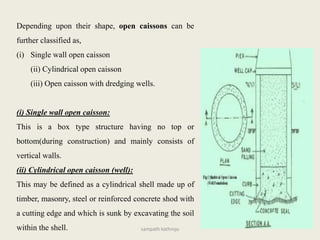
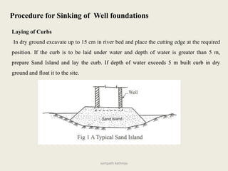
Downloaded 1,511 times

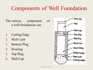
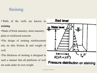
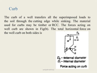
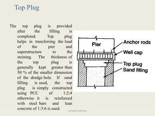
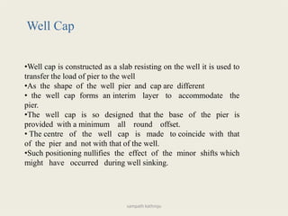
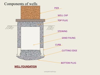
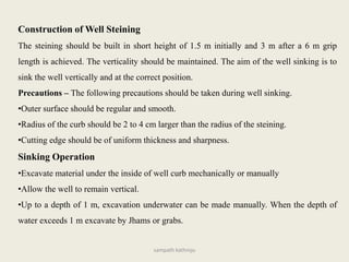
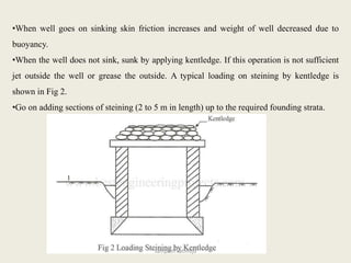

The document discusses different types of well foundations used in construction. It describes the key components of well foundations including the cutting edge, steining, bottom plug, top plug, and well cap. It explains the process of sinking well foundations, which involves excavating material inside the well curb to allow the well to sink vertically into the ground. Precautions like maintaining verticality and limiting tilt and shift are important during well sinking.