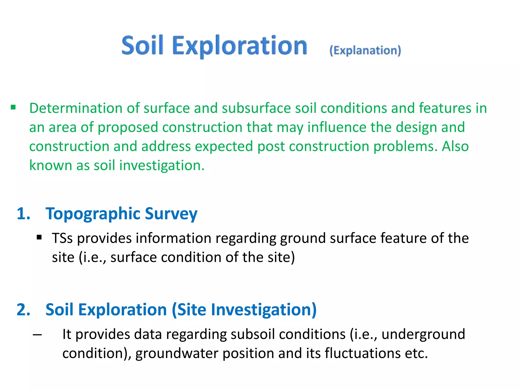
 Determination of surface and subsurface soil conditions and features in
an area of proposed construction that may influence the design and
construction and address expected post construction problems. Also
known as soil investigation.
1. Topographic Survey
 TSs provides information regarding ground surface feature of the
site (i.e., surface condition of the site)
2. Soil Exploration (Site Investigation)
– It provides data regarding subsoil conditions (i.e., underground
condition), groundwater position and its fluctuations etc.
The primary objective of the site investigation is as follows:
1. To assess the sequence, thickness and lateral extent of the soil
strata and, where appropriate, the level of bedrock.
2. To obtain representative samples of the soils (and rock) for
identification and classification to determine the relevant soil
parameters.
3. To determine the position of GWT and limits of its fluctuation
during wet/dry season.
Thus exploration essentially provides information to decide about:
i) The suitability of the site for proposed work ii) To develop
economical design iii) To predict any construction problems along
with their possible remedies.
1. Feasibility Phase (Reconnaissance):
It generally involves collection of background information
about the site. Following information is collected:
– Project Details
• Type of structure, intended use of structure, construction method, etc.
– Surface and Subsurface Conditions of the site
• Study of topographic/geologic maps, aerial photographs, data from previous
investigations, satellite imagery, etc.
– Study of existing structures in the area
2. Preliminary Investigation
– Location of bedrock is established by drilling a few holes. Position
of GWT may also be established.
3. Detailed Investigation
– This phase may include test pits excavation, boreholes, in-situ
testing and collection of both disturbed and undisturbed soil
samples for detailed laboratory testing/analysis. GWT may also be
monitored by installing piezometers.
4. Construction/Post Construction Investigation
– Sometimes monitoring of movement of structure and monitoring
of groundwater fluctuations, both during and after construction,
may be required.
 By amount of exploration is meant to decide about the extent of
investigation i.e., to determine the number, location, and depth
of open excavations (pits, trenches, etc.) and borings/drillings.
The extent of exploration depends upon many factors, major
being the following:
1. Site condition (variability of soil/rock strata and GWT depth at site)
2. Nature and extent of the project. (building, highway, dam, etc.)
3. Availability of time, fund and equipment for exploration.
 The main rule for determining the extent of investigations is that
there is no hard and fast rule for this purpose.
 The methods to determine the sequence, thickness and lateral
extent of the soil strata and, where appropriate the level of
bedrock. The common methods include:
1. Test pits
2. Boring or drilling
 The excavation of test pits is a simple and reliable method.
 The maximum depth is limited to 4-5m only.
 If the pit is to be extend below the GWT, some form of dewatering is
necessary.
 The in-situ conditions are examined visually.
 It is easy to obtain disturbed and undisturbed samples.
 Block samples can be cut by hand tools and tube samples can be taken
from the bottom of the pit.
 Test pits are suitable for investigations in all type of soil, including those
containing cobbles or boulders.
 Walls of the test pit indicate four layers (1) Clayey silt (2) Sandy
silt (3) Clean sand (4) Sandy gravel
 Boring refers to advancing a hole in the ground.
 Boring is required for the following:
 To obtain representative soil and rock samples for laboratory tests.
 To identify the groundwater conditions.
 Performance of in-situ tests to assess appropriate soil characteristics.
 Some of the common types of boring are as follows:
 Auger boring
 Hand Augar
 Mechanical Augar
 Rotary drilling
 Wash boring
 Percussion boring
1. Hand Augar:
• The hand augar (also called post-hole or Iwan augar) is a very simple hand
tool used for drilling into soft soils down to maximum of 5-6m in small
projects.
• Hand-augered holes can be made up to about 20m depth, although depth
greater than about 8-10m is usually not practical.
• For hard soil and soil containing gravels boring with hand auger becomes
difficult.
• The auger is rotated until it is full of soil, then it is withdrawn to remove the
soil and the soil type present at various depths is noted.
• They can be used for soil exploration work for highways and small structures.
• The soil samples collected in this manner are disturbed but they can be used
for classification test in laboratory such as grain-size determination and
Atterberg limits.
• Auger boring may not be possible in very soft clay or coarse sand because the
hole tends to collapse when auger is removed.
a
Continuous Flight Auger
Truck mounted auger boring machine
Hand Augar
a) Plugged while advancing the auger
b) Plug removed and sampler attached
2. Mechanical Augar:
• Mechanical Auger means power operated augers. The power required to rotate the
auger depends on the type and size of auger and the type of soil.
• Downwards pressure can be applied hydraulically, mechanically or by dead weight.
• The diameter of the flight auger usually is between 75 to 300mm, although diameters
up to 1m and bucket augers up to 2m are available.
• Borehole depths up to 50m are possible with continuous-flight augers.
• The most common method is to use continuous flight augers. Continuous flight augers
can be solid stem or hollow stem with internal diameter of 75-150mm.
• Hollow stem augers are used when undisturbed samples are required. Plug is
withdrawn and sampler is lowered down and driven in to the soil below the auger.
• If bed rock is reached drilling can also take place through the hollow stem.
• The presence of cobbles and boulders create problems with small-sized augers.
• There is a possibility that different soil types may become mixed as they rise to the
surface and it may be difficult to determine the depths of changes of strata.
Experienced driller can however detect the change of strata by the change of speed
and the sound of drilling.
 Although primarily intended for investigations in rock, the
method is also used in soils.
 Rotary drilling is a procedure by which rapidly rotating drilling
bits attached to the bottom of drilling rods cut and grind the soil
and advance the borehole down.
 Water or drilling fluid is pumped down the hollow rods and
passes under pressure through narrow holes in the bit or barrel:
this is the same principle as used in wash boring.
Various types of diamond drill
bits for rotary drilling
Rotary Drilling
 There are two forms of rotary drilling, open-hole drilling and core
drilling.
 Open-hole drilling, which is generally used in soils and weak rock, uses a
cutting bit to break down all the material within the diameter of the hole.
Open-hole drilling can thus be used only as a means of advancing the
hole: the drilling rods can then be removed to allow tube samples to be
taken or in-situ tests to be carried out.
 In core drilling, which is used in rocks and hard clays, the diamond bit cuts
an annular hole in the material and an intact core enters the barrel, to be
removed as a sample. However, the natural water content of the material
is liable to be increased due to contact with the drilling fluid.
 Wash boring is another method of advancing a borehole.
 In this method, a casing about 2m to 3m (6 to 10 ft) long is driven
into the ground.
 The soil inside the casing is then removed by means of a
chopping bit that is attached to a drilling rod.
 Water is forced through a drilling rod, and it goes out at a very
high velocity through the holes at the bottom of the chopping
bit.
 The water and the chopped soil particles rise upward in the drill
hole and overflow at the top of the casing through a T-
connection.
 The wash water is then collected in a container.
• Percussion drilling is an alternative
method of advancing a borehole,
particularly through hard soil and rock.
• The boring rig consists of a derrick, a
power unit and a winch carrying a light
steel cable which passes through a
pulley on top of the derrick.
• In this technique, the borehole is
advanced by the percussive action of
the tool which is alternately raised and
dropped (usually over a distance of 1–
2m) by means of the winch unit.
• Borehole diameters can range from 150
to 300mm. The maximum borehole
depth is generally between 50 and
60m.
 This test gives information about soil strength.
 It is carried out at regular intervals during a boring operation or
where change of strata is noted.
 A split-spoon sampler is attached to the drill rods, lowered to the
bottom of boreholes and driven into the ground by repeated
blows of a standard 65kg hammer falling freely through 75cm.
 The number of blows requires to drive the sampler through three
consecutive depths of 15cm (total 45cm) are noted.
 The SPT N value is the number of blows required to drive the
sampler through the last 30cm.
 If, for N > 50, the sampler penetrates less than 2.5cm, refusal is
said to have been reached and the test is discontinued until the
boring advances to a new depth.
Standard Penetration Test (SPT) per ASTM D 1586
 The standard penetration test is very useful for cohesionless soils
and medium clays.
 For gravels and stiff clays the results are not reliable.
 The SPT test is very popular all over the world. It is simple, not
too expensive, reliable, and generally repeatable.
 It is extensively used in problems such as design of foundations,
settlement analysis and liquefaction studies.
 Among the sources of error are that:
 The hammer should freely and through the correct distance
 The sampler should be held vertically
 The drill rods longer than 15m are likely to whip.
 This test provides a continuous record of resistance offered by a soil to a cone
pushed into it.
 The cone usually has a vertex angle of 60 and a base diameter of 50mm, but cones
of different dimensions are also used.
 It is attached to the end of the drill rod and pushed into the borehole by means of
jack.
 The resistance offered and the corresponding depth are recorded. This called a
static cone penetration test.
 In dynamic cone penetration test (DCPT) the cone is driven by the blows of a 65kg
hammer (the same as in the SPT).
 The number of blows required to drive the cone 30cm into the ground is noted.
 The CPT is a useful test for gravel and coarse sand formations, especially below
water table.
 A CPT test is best used to corroborate the results of SPT or other test.
 A sample is said to be representative sample when it truly
represents the characteristics of the stratum from which it is
recovered.
1. Disturbed Sample:
 A disturbed sample is one having the same particle size distribution as the
in-situ soil but in which natural moisture content is disturbed and soil
structure has been significantly damaged or completely destroyed.
 Disturbed samples, which are used mainly for soil classification tests,
visual classification and compaction tests, can be excavated from trial pits.
2. Undisturbed Sample:
 Undisturbed samples are obtained by techniques which aim at
preserving the in-situ structure and water content of the soil.
 It is impossible to obtain a sample that is completely undisturbed, no
matter how elaborate or careful the ground investigation and sampling
technique might be.
 Undisturbed samples are used to determine the shear strength,
compressibility and permeability of the materials.
 All samples should be clearly labelled to show the project name, date,
location, borehole number, depth and method of sampling.
 Special care is required in the handling, transportation and storage of
samples prior to testing.
1. Sampling by Standard Split Spoon
 When the borehole is advanced to a desired depth, the drilling tools are
removed. The split-spoon sampler is attached to the drilling rod and then
lowered to the bottom of the borehole. The sampler is driven into the soil
at the bottom of the borehole by means of hammer blows. The hammer
blows occur at top of the drilling rod. The hammer weighs 63.5kg (140lb).
For each blow, hammer drops a distance of 30in (.76m). The number of
blows required for the driving the sampler through three 6in interval is
recorded. The sum of the number of blows required for driving the last
two 6in interval is referred to as the Standard Penetration Number, N. It
is commonly called the blow count. The interpretation of the standard
penetration number is given in the following table.
Standard Split-spoon Sampler
2. Sampling by Thin Wall Tube
 It is used for obtaining fairly undisturbed soil samples. The thin wall tubes
are made of seamless thin tubes and are commonly referred to as Shelby
Tubes. The sampler is attached to the drilling rod and then lowered to the
bottom of the borehole. After this, it is hydraulically pushed into the soil. It
is then spun to shear off the base and is pulled out. The sampler with the
soil inside is sealed and taken to the laboratory for testing. Most
commonly used thin wall tube samplers have outside diameter of 3in.
 Sample Disturbance
 The degree of disturbance of the sample collected by various method can
be expressed by a term called the area ratio, which is given by
Ar = (Do
2 – Di
2) / Di
2
where Di and Do are inside and outside diameter of sampler respectively.
Geotechnical Engineering II
Slope Stability
Contents
 Introduction
 Types of slope movements
 Concepts of Slope Stability Analysis
 Factor of Safety
 Stability of Infinite Slopes
 Stability of Finite Slopes with Plane Failure Surface
o Culmann’s Method
 Stability of Finite Slopes with Circular Failure Surface
o Mass Method
o Method of Slices
Introduction
What is a Slope?
An exposed ground surface that stands at an angle with the
horizontal.
Why do we need slope stability?
In geotechnical engineering, the topic stability of slopes deals with:
1.The engineering design of slopes of man-made slopes in
advance
(a) Earth dams and embankments,
(b) Excavated slopes,
(c) Deep-seated failure of foundations and retaining walls.
2. The study of the stability of existing or natural slopes of
earthworks and natural slopes.
o In any case the ground not being level results in gravity
components of the weight tending to move the soil from the
high point to a lower level. When the component of gravity is
large enough, slope failure can occur, i.e. the soil mass slide
downward.
o The stability of any soil slope depends on the shear strength of the soil
typically expressed by friction angle (f) and cohesion (c).
Types of Slopes
A. Natural slope
• Hill sides
• Mountains
• River banks
B. Man-made slope
• Fill (Embankment)
• Earth dams
• Canal banks
• Excavation sides
• Trenches
• Highway Embankments
Slopes can be categorized
into two groups:-
• Some of these failure can cause dramatic impact on lives
and environment.
Slope failures cost billions of $
every year in some countries
Case histories of slope failure
Bolivia, 4 March 2003, 14 people killed, 400 houses buried
Central America??
Brazil, January 2003, 8 people killed
o Human activities disturb large volumes of earth materials
in construction of buildings, transportation routes, dams
and reservoirs, canals, and communications systems, and
thus have been a major factor in increases in damages due
to slope failures.
LaConchita California Slump
Slides: Rotational (slump)
Contents
 Introduction
 Types of slope movements
 Concepts of Slope Stability Analysis
 Factor of Safety
 Stability of Infinite Slopes
 Stability of Finite Slopes with Plane Failure Surface
o Culmann’s Method
 Stability of Finite Slopes with Circular Failure Surface
o Mass Method
o Method of Slices
Types of Slope Movements
 Falls
 Topples
 Slides
 Flows
 Creep
 Lateral spreads
 Complex
o Slope instability (movement) can be classified into six
different types:
I. Falls
• Rapidly moving mass of material (rock or soil) that travels mostly through the
air with little or no interaction between moving unit and another.
• As they fall, the mass will roll and bounce into the air with great force and thus
shatter the material into smaller fragments.
• It typically occurs for rock faces and usually does not provide warning.
• Analysis of this type of failure is very complex and rarely done.
• Gravitational effect and shear strength
Gravity has two components of forces:
T driving forces:
N resisting forces (because of friction);
T= W. sin b
N = W. cos b
T
S = N tan f
the interface develop its
resistance from friction (f):
b
A = effective Base Area of sliding block
f = friction
N
S
In terms of stresses:
S/A = N/A tan f
tf = s tan f
or
Boulder
II. Topples
This is a forward rotation of soil and/or rock mass about an axis below the
center of gravity of mass being displaced.
Back-Scrap
Bulging at
Toe
III. Slides
Slides
A. Translational (planar)
o Movements occur along planar failure surfaces that may run
more-or less parallel to the slope. Movement is controlled by
discontinuities or weak bedded planes.
A
Weak bedding
plane
(Planar)
Occur when soil of significantly different
strength is presented
B. Rotational (curved)
This is the downward movement of a soil mass occurring on an
almost circular surface of rupture.
B
Back-Scrap
Bulging
Curved escarpment
(Slumps)
C. Compound (curved)
Soil nails
Reinforcement
‫شدادات‬
Reinforcement
Possible failure
surface
Anchors
o The materials moves like a
viscous fluid. The failure plane
here does not have a specific
shape.
IV. Flows
It can take place in soil
with high water content
or in dry soils. However,
this type of failure is
common in the QUICK
CLAYS, like in Norway.
V. Creep
• It is the very slow movement of slope material that occur
over a long period of time
• It is identified by bent post or trees.
o Lateral spreads usually occur on very gentle slopes or essentially flat terrain,
especially where a stronger upper layer of rock or soil undergoes extension
and moves above an underlying softer, weaker layer.
weaker layer
VI. Lateral spreads
1. Falls
2. Topples
3. Slides
• A. Translational (planar)
• B. Rotational (slumps)
4. Flow
5. Creep
6. Complex
Complex movement is by a combination of one
or more of the other principal types of
movement.
Many slope movements are complex,
although one type of movement generally
dominates over the others at certain areas or
at a particular time.
VII. Complex
Mass Movements: Five Main Types
Factors Affecting Stability of Slopes
Causes of Slope Failure
1. External causes
These which produce increase of shear stress, like steepening
or heightening of a slope, building on the top of the slope
2. Internal causes
These which cause failure without any change in external
conditions, like increase in pore water pressure.
Therefore, slopes fail due either to increase in stress or
reduction in strength.
Concept of Instability
o Instability occurs when the shear stresses t that cause
movement (e.g. gravitational forces W) overcome the
internal shear strength tf of the soil (cohesion C and friction f
between the soil grains) along potential plane of failure.
W
(f ,c)
Stress
Shear
Strength
Shear
safety
of
Factor 
FS
t
t
tf
(f ,c)
tf
(f ,c)
tf
Accordingly, the factors causing
instability may be divided to:
• Factors causing increased Shear
Stresses t
• Factors causing a reduction in
Shear Strength tf
1. Falls
2. Topples
3. Slides
• Translational (planar)
• Rotational (curved)
4. Flows
5. Creep
6. Lateral spreads
7. Complex
Slide is the most common
mode of slope failure, and
it will be our main focus in
this course
Types of Slope Failures Considered in this Course
In general, there are six types of slope failures:
Types of Slide Failure Surfaces
• Failure of slopes generally occur along surfaces known as
failure surfaces. The main types of surfaces are:
• Planar Surfaces: Occurs in
frictional, non cohesive soils
• Rotational surfaces: Occurs in cohesive soils
Circular surface
(homogeneous soil)
Non-circular surface
(non-homogeneous soil)
• Transitional Slip Surfaces:
When there is a hard stratum at a
relatively shallow depth
• Compound Slip Surfaces:
When there is hard stratum at some depth that intersects
with the failure plane
Slides
Translational
(planar)
Infinite
Long plane
failure surface
Finite
Plane failure
surface
Rotational
(curved)
Finite
Above the toe
Through the toe
Deep seated
Failure surface 1
2
3
Types of Failure Surfaces Considered in this Course
Stability of infinite slopes
Stability of finite slopes with plane failure
surfaces
Stability of finite slopes with circular
failure surfaces
1
2
3
Types of slope failures considered in this course
Contents
 Introduction
 Types of slope movements
 Concepts of Slope Stability Analysis
 Factor of Safety
 Stability of Infinite Slopes
 Stability of Finite Slopes with Plane Failure Surface
o Culmann’s Method
 Stability of Finite Slopes with Circular Failure Surface
o Mass Method
o Method of Slices
In general we need to check
o The stability of a given existed slope
o Determine the inclination angle for a slope that we want to build with a
given height
o The height for a slope that we want to build with a given inclination.
Concepts of Slope Stability Analysis
It is a method to expresses the relationship between resisting forces and
driving forces
• Driving forces – forces which move earth materials downslope. Downslope
component of weight of material including vegetation, fill material, or
buildings.
• Resisting forces – forces which oppose movement. Resisting forces include
strength of material
• Failure occurs when the driving forces (component of the
gravity) overcomes the resistance derived from the shear
strength of soil along the potential failure surface.
Methodology of Slope Stability Analysis
1. Assume a probable failure surface
Slope Stability Analysis Procedure
4. Based on the minimum FS, determine whether the slope is safe or not.
3. Repeat steps 1 and 2 to determine the most likely failure surface. The
most likely failure surface is the critical surface that has a minimum
factor of safety.
2. Calculate the factor of safety by determining and comparing the shear
stress developed along the most likely rupture surface to the shear
strength of soil.
The analysis involves determining and comparing the shear stress developed
along the most likely rupture surface to the shear strength of soil.
Methods of Slope Stability Analysis
o Limit equilibrium
o Limit analysis
o Numerical methods
We will consider only the limit equilibrium method, since it is
the oldest and the mostly used method in practice.
Assumptions of Stability Analysis
o The problem is considered in two-dimensions
o The failure mass moves as a rigid body
o The shear strength along the failure surface is isotropic
o The factor of safety is defined in terms of the average shear
stress and average shear strength along the failure surface
Contents
 Introduction
 Types of slope movements
 Concepts of Slope Stability Analysis
 Factor of Safety
 Stability of Infinite Slopes
 Stability of Finite Slopes with Plane Failure Surface
o Culmann’s Method
 Stability of Finite Slopes with Circular Failure Surface
o Mass Method
o Method of Slices
Fs is the ratio of resisting forces to the driving forces, or
Factor of Safety
• The most common analytical methods of slope stability use a factor of
safety FS with respect to the limit equilibrium condition,
FS < 1  unstable
FS ≈ 1  marginal
FS >> 1  stable
Generally, FS ≥ 1.5 is
acceptable for the design of a
stable slope
average shear strength of the soil.
average shear stress developed
along the potential failure surface.
W
(f ,c)
td
tf
(f ,c)
tf
(f ,c)
tf
H
td
Shear stress (driving movement)
Shear strength (resisting movement)
(developed)
(Available)
o If factor safety Fs equal to or less than
1, the slope is considered in a state of
impending failure.
Where:
c’ = cohesion
f’ = angle of internal friction
= cohesion and angle of
friction that develop along
the potential failure surface
d
d
c f
 ,
f
f 


 

 F
F
F
F
F c
s
c then
When
Factor of safety with respect to cohesion
Factor of safety with respect to friction
When the factor of safety with respect to cohesion is equal to the factor of
safety with respect to friction, it gives the factor of safety with respect to
strength, or
Other aspects of factor of safety
Contents
 Introduction
 Types of slope movements
 Concepts of Slope Stability Analysis
 Factor of Safety
 Stability of Infinite Slopes
 Stability of Finite Slopes with Plane Failure Surface
o Culmann’s Method
 Stability of Finite Slopes with Circular Failure Surface
o Mass Method
o Method of Slices
 What is an Infinite slope?
• Slope that extends for a relatively long distance and has
consistent subsurface profile can be considered as infinite
slope.
• Failure plane parallel to slope surface.
• Depth of the failure surface is small compared to the height
of the slope.
• For the analysis, forces acting on a single slice of the sliding
mass along the failure surface is considered and end effects
is neglected.
Stability of Infinite Slopes
Force parallel to the plane AB Ta = W sin b = g LH sin b
I. Infinite slope – no seepage
o we will evaluate the factor of safety against a possible slope failure
along a plane AB located at a depth H below the ground surface.
o Let us consider a slope element abcd that has a unit length
perpendicular to the plane of the section shown.
o The forces, F, that act on the faces ab and cd are equal and opposite and
may be ignored.
The shear stress at the base of the slope element can be given by
The resistive shear stress is given by
…….(#)
The effective normal stress at the base of the slope element is given by
…….(##)
The depth of plane along which critical
equilibrium occurs is obtained by
substituting Fs = 1 and H = Hcr into Eq. (###).
Critical Depth, Hcr
For Granular Soil (i.e., c = 0)
b
f
tan
tan 

s
F
This means that in case of
infinite slope in sand, the
value of Fs is independent of
the height H and the slope is
stable as long as b < f’
…….(###)
Equating R.H.S. of Eqs. (#) and (##) gives
• Case of Granular soil – Derivation From Simple Statics
• Equilibrium of forces on a slice:

FS
Driving Forces
Resisting Forces
L
L
Extra
II. Infinite Slope – With Steady State Seepage
(*)
(**)
Seepage is assumed to be parallel to the slope and
that the ground water level coincides with the ground
surface.
The resistive shear stress developed at the
base of the element is given by
The shear stress at the base of
the slope element can be given
Substituting Eq. (****) Into Eq. (***) and solving for Fs gives
Equating the right-hand sides of Eq. (*) and Eq. (**) yields
b
f
b
b
g tan
tan
tan
cos
H
c
2




s
F
No seepage
(***)
(****)
Recall
𝑭𝑺 =
𝒄′
𝜸. 𝑯 . 𝐜𝐨𝐬 𝜷 . 𝐬𝐢𝐧 𝜷
+ (𝟏 −
𝒖
𝜸. 𝑯. 𝒄𝒐𝒔𝟐 𝜷
)
𝒕𝒂𝒏 𝝋′
𝒕𝒂𝒏 𝜷
𝝉𝒅 =
𝒄′
𝑭𝒔
+ (𝝈 − 𝒖)
𝒕𝒂𝒏 𝝋′
𝑭𝒔
EXTRA
General Case of Seepage
𝝈′ =
𝑵𝒂
𝑨𝒓𝒆𝒂 𝒐𝒇 𝒃𝒂𝒔𝒆
=
𝜸𝑯𝑳.𝒄𝒐𝒔𝟐 𝜷
𝑳
𝑪𝒐𝒔𝜷
=𝐴 = 𝜸𝑯. 𝒄𝒐𝒔𝟐 𝜷
𝝉𝒅 =
𝒄′
𝑭𝒔
+ (𝜸𝑯. 𝒄𝒐𝒔𝟐 𝜷 − 𝒖)
𝒕𝒂𝒏 𝝋′
𝑭𝒔
($)
($$)
Equating R.H.S of ($) and ($$) and rearranging gives The challenge here is to
evaluate the value of u.
We need to go to seepage
problems
If no water (u = 0):
With water seepage:
𝑭𝑺 =
𝒄′
𝜸 . 𝑯 . 𝐜𝐨𝐬 𝜷 . 𝐬𝐢𝐧 𝜷
+ (𝟏 −
𝒖
𝜸. 𝑯. 𝒄𝒐𝒔𝟐 𝜷
)
𝒕𝒂𝒏 𝝋′
𝒕𝒂𝒏 𝜷
H
If no water (u = 0) and
soil is granular (C’=0) :
𝑭𝑺 =
𝒕𝒂𝒏 𝝋′
𝒕𝒂𝒏 𝜷
𝑭𝑺 =
𝒄′
𝜸. 𝒉 . 𝐜𝐨𝐬 𝜷 . 𝐬𝐢𝐧 𝜷
+
𝒕𝒂𝒏 𝝋′
𝒕𝒂𝒏 𝜷
Summary of Stability of Infinite Slopes
(The ground water level coincides
with the ground surface)
𝒖 = 𝜸. 𝑯. 𝒄𝒐𝒔𝟐 𝜷
Extra
From Eq. 15.28
Contents
 Introduction
 Types of slope movements
 Concepts of Slope Stability Analysis
 Factor of Safety
 Stability of Infinite Slopes
 Stability of Finite Slopes with Plane Failure Surface
o Culmann’s Method
 Stability of Finite Slopes with Circular Failure Surface
o Mass Procedure
o Method of Slices
o For simplicity, when analyzing the stability of a finite slope
in a homogeneous soil, we need to make an assumption
about the general shape of the surface of potential failure.
o However, considerable evidence suggests that slope
failures usually occur on curved failure surfaces
,
o The simplest approach is to approximate the surface of
potential failure as a plane.
o Hence most conventional stability analyses of slopes have
been made by assuming that the curve of potential sliding
is an arc of a circle.
Stability of Finite Slopes with Plane Failure Surface
Plane Failure Surface
simple wedge
o Culmann’s analysis is based on the assumption that the failure
of a slope occurs along a plane when the average shearing
stress tending to cause the slip is more than the shear strength
of the soil.
o Also, the most critical plane is the
one that has a minimum ratio of the
average shearing stress that tends
to cause failure to the shear
strength of soil.
o The method gives reasonably
accurate results if the slope is
vertical or nearly vertical.
• Culmann’s method assumes that the critical surface of failure is
a plane surface passing through the toe.
Culmann’s Method
• The forces that act on the mass are shown in the figure, where
trial failure plane AC is inclined at angle q with the horizontal.
• A slope of height H and that rises at an angle b is shown below.
The average shear stress on the
plane AC
Ta
= W Sin q
Similar procedures as for infinite slope, only different
geometry. Also here we made optimization.
t (&)
The average resistive shearing stress (Developed shear strength) developed
along the plane AC also may be expressed as
Na
s’
td (&&)
Equating the R.H.S of Eqs. (&) and (&&) gives
(&&&)
• To determine the critical failure plane, we must use the
principle of maxima and minima (for Fs=1 and for given values
of c’, f’, g, H, b) to find the critical angle q:
Critical failure plane
• The expression in Eq. (&&&) is derived for the trial failure
plane AC.
• Substitution of the value of q = qcr into Eq. (&&&) yields
(&&&&)
• For purely cohesive soils c  0 f = 0.
𝜽𝒄𝒓 =
𝜷
𝟐
𝑯𝒄𝒓 =
𝟒𝒄′
𝜸
𝐬𝐢𝐧 𝜷
𝟏 − 𝐜𝐨𝐬 𝜷
The maximum height of the slope for which critical equilibrium occurs can
be obtained by substituting iinto into Eq. (&&&&)
A cut is to be made in a soil having properties as shown in the figure
below.
If the failure surface is assumed to be finite plane, determine the
followings:
(a) The angle of the critical failure plane.
(b) The critical depth of the cut slope
(c) The safe (design) depth of the cut slope. Assume the factor of safety
(Fs=3)?
Example
H
45o
g = 20 kN/m3
f’=15o
c’=50 kPa
Given equation:
(a) The angle of the critical failure
plane q can be calculated from:
(b) The critical depth of the cut
slope can be calculated from:
H g = 20 kN/m3
f’=15o
c’=50 kPa
45o
Key Solution:
b  45o
f’ 15o
d
(c) The safe (design) depth of the
cut slope.
where: c’d and f’d can be determined from:
III. Given H, b, q, c’ and f’ required factor of safety
I. Given b, c’ and f’ required critical height
II. Given b, Fs, c’ and f’ required height for the given factor of safety
Directly from
• Assume Ff
Possible Cases
• Solve for H
• tan fd = tan f/Ff
• Find Cd
• Fc = C/Cd
• Repeat until Fc = Ff
2nd Midterm Fall 1436-1437H (QUESTION #1)
A cutting is to be excavated in a clay stratum at an angle that is equal to 60o.
The relevant parameters are g= 17 kN/m3
, c = 20 kN/m2 and f = 25o. Assume
the failure mechanism to be planar (i.e. Cullman’s method) and determine:-
a. The height of the excavation that will have a factor of safety of 1.5 against
sliding.
b. The critical height of the excavation.
c. Repeat (b) if the soil is purely cohesive. Compare the answer with the result
of part (b) and comment.
Solution
Mother equation
Contents
 Introduction
 Types of slope movements
 Concepts of Slope Stability Analysis
 Factor of Safety
 Stability of Infinite Slopes
 Stability of Finite Slopes with Plane Failure Surface
o Culmann’s Method
 Stability of Finite Slopes with Circular Failure Surface
o Mass Method
o Method of Slices
• Modes of Failure
Shallow slope
failure
Finite Slopes with Circular Failure Surface
i. Slope failure
• Surface of sliding intersects the slope
at or above its toe.
o The failure circle is referred to as a slope
circle if it passes above the toe of the slope.
• Under certain circumstances, a
shallow slope failure can occur.
o The failure circle is referred to as a toe circle
if it passes through the toe of the slope
ii. Shallow failure
Firm Base
H
iii. Base failure
o The surface of sliding passes
at some distance below the
toe of the slope.
o The circle is called the
midpoint circle because its
center lies on a vertical line
drawn through the midpoint of
the slope.
o For b  53o always toe
o For b < 53o could be toe, slope, or midpoint and that depends on depth
function D where:
Depth function:
Various procedures of stability analysis may, in general, be
divided into two major classes:
2. Method of slices
1. Mass procedure
Types of Stability Analysis Procedures
• In this case, the mass of the soil
above the surface of sliding is
taken as a unit.
• Most natural slopes and many
man-made slopes consist of
more than on soil with different
properties.
• This procedure is useful when
the soil that forms the slope is
assumed to be homogeneous.
• In this case the use of mass
procedure is inappropriate.
• In the method of slices procedure, the soil above the
surface of sliding is divided into a number of vertical parallel
slices. The stability of each slice is calculated separately.
b
2
1
1
2
W
V
E
E
V T
N'
a
h
R
R
O
W
x
a
• It is a general method that can be used for analyzing
irregular slopes in non-homogeneous slopes in which the
values of c’ and f’ are not constant and pore water pressure
can be taken into consideration.
Contents
 Introduction
 Types of slope movements
 Concepts of Slope Stability Analysis
 Factor of Safety
 Stability of Infinite Slopes
 Stability of Finite Slopes with Plane Failure Surface
o Culmann’s Method
 Stability of Finite Slopes with Circular Failure Surface
o Mass Method
o Method of Slices
2. Slopes in Homogeneous clay Soil with c  0 , f = 0
Determining factor of safety using equilibrium equations (Case I)
Mdriving = Md = W1l1 – W2l2
W1 = (area of FCDEF) g
W2 = (area of ABFEA) g
Mresisting = MR = cd (AED) (1) r
= cd r2q
I. Mass Procedure
1.Slopes in purely cohesionless soil with c = 0, f  0
Failure generally does not take place in the form of a circle. So
we will not go into this analysis.
𝑭𝒔 =
𝒓𝟐𝜽𝒄𝒖
𝒘𝟏𝒍𝟏 − 𝒘𝟐𝒍𝟐
W1
W2
l1
l2
𝑭𝒔 =
𝒓𝟐𝜽𝒄𝒖
𝒘𝟏𝒍𝟏 − 𝒘𝟐𝒍𝟐
MR = cu r2q
Mdriving = Md = W1l1 – W2l2
Mresisting = MR = cd r2q
• The minimum value of the factor of safety thus obtained is
the factor of safety against sliding for the slope, and the
corresponding circle is the critical circle.
• The potential curve of sliding, AED, was chosen arbitrarily.
•The critical surface is that for which the ratio of Cu to Cd is a
minimum. In other words, Cdis maximum.
• To find the critical surface for sliding, one must make a
number of trials for different trial circles.
REMARKS
• Fellenius (1927) and Taylor (1937) have analytically solved for
the minimum factor of safety and critical circles.
• They expressed the developed cohesion as
H
or
soil
of
t
unit weigh
γ
slope
of
height
H
number
Stability
m
Where
g
g
d
d
c
m
m
H
c





• We then can calculate the min Fs as
𝑯𝒄𝒓=
𝑪𝒖
𝛄𝒎
𝑭𝒔=
𝑪𝒖
𝜸𝑯𝒎
• The critical height (i.e., Fs 1) of the slope can be
evaluated by substituting H = Hcr and cd = cu (full
mobilization of the undrained shear strength) into the
preceding equation. Thus,
 The results of analytical solution to obtain critical circles was represented
graphically as the variation of stability number, m , with slope angle b.
Toe, Midpoint or slope circles
Toe slope
Firm Stratum
b
m is obtained from this chart depending on angle b.
 Failure Circle
 For a slope angle b > 53°, the critical circle is always a toe circle. The
location of the center of the critical toe circle may be found with the aid of
Figure 15.14.
 For b < 53°, the critical circle may be a toe, slope, or midpoint circle,
depending on the location of the firm base under the slope. This is called
the depth function, which is defined as
(radius)
Figure 15.14
Location of the center of the critical toe circle
The location of the center of the
critical toe circle may be found
with the aid of Figure 15.14
When the critical circle is a midpoint circle (i.e., the
failure surface is tangent to the firm base), its position
can be determined with the aid of Figure 15.15.
Figure 15.15
Firm base
The location of these circles can be
determined with the use of Figure
15.16 and Table 15.1.
Figure 15.16
Note that these critical toe circle are not necessarily the most critical
circles that exist.
Critical toe circles for
slopes with b < 53°
How to use the stability chart?
Given: b  60o, H, g, cu Required: min Fs
m = 0.195
1. Get m from chart
2. Calculate cd from
3. Calculate Fs
m
H
cd g

d
u
s
c
c
F 
How to use the previous chart?
Given: b 30o, H, g, cu, HD (depth to hard stratum) Required: min. Fs
m = 0.178
1. Calculate D = HD/H
2. Get m from the chart
3. Calculate cd from
4. Calculate Fs
m
H
cd g

d
u
s
c
c
F 
D = Distance from the top surface of slope to firm base
Height of the slope
Note that recent investigation put angle b at 58o instead of the 53o value.
Rock layer
D=1.5m
𝑭𝒔=
𝑪𝒖
𝜸𝑯𝒎
 The results of analytical solution to obtain critical circles was represented
graphically as the variation of stability number, m , with slope angle b.
Toe, Midpoint or slope circles
Toe slope
Firm Stratum
b
m is obtained from this chart depending on angle b.
2. Slopes in Homogeneous clay Soil with c  0 , f = 0
o The Friction Circle method (or the f-
Circle Method) is very useful for
homogenous slopes. The method is
generally used when both cohesive and
frictional components are to be used.
3. Slopes in Homogeneous C’ – f’ Soils
o Here the situation is more complicated
than for purely cohesive soils.
o 𝑨𝑪is a trial circular arc that passes
through the toe of the slope, and O
is the center of the circle.
o The pore water pressure is assumed to be zero
o F—the resultant of the normal and
frictional forces along the surface of
sliding. For equilibrium, the line of action
of F will pass through the point of
intersection of the line of action of W
and Cd.
o Several trails must be made to obtain the most critical sliding surface,
(minimum factor of safety or along which the developed cohesion is a
maximum).
(  number
stability
m
f
cd
,
,
,
H





f
q
b
a
g
( 
 
f
q
b
a
g 

 ,
,
,
H f
cd
o The maximum cohesion developed along the critical surface as
o Determination of the magnitude of described previously is based on a
trial surface of sliding.
o The results of analytical solution to obtain minimum Fs was represented
graphically as the variation of stability number, m , with slope angle b for
various values of f’ (Fig. 15.21).
o Solution to obtain the minimum Fs using this graph is performed by trial-
and-error until Fs = Fc’=Ff’
o Since we know the magnitude and direction of W and the direction of Cd and F
we can draw the force polygon to get the magnitude of Cd.
o We can then calculate c’d from
( 
 
f
q
b
a
g 

 ,
,
,
H f
cd
m
H
cd g

Given: H, b, g, c’, f’ Required: Fs
1.Assume fd (Generally start with = f’
i.e. full friction is mobilized)
2. Calculate
3.With fd and b Use Chart to get m
4.Calculate
5.Calculate
6. If Fc’ = Ff’ The overall factor of safety
Fs = Fc’ = Ff’
7. If Fc’≠ Ff’ reassume fd and repeat
steps 2 through 5 until Fc’ = Ff’
Or
Plot the calculated points on Fc versus Fφ
coordinates and draw a curve through the
points. [see next slide]. Then Draw a line
through the origin that represents Fs= Fc = Fφ
m
H
cd g

d
c
c
c
F


Procedures of graphical solution
Taylor’s stability
number
Note: Similar to Culmann procedure for planar mechanism but here Cd is
found based on m. In Culmann’s method Cd is found from analytical
equation.
Hcr means that Fc’ = Ff’ =Fs = 1.0
1. For the given b and f’, use Chart
to get m.
2.Calculate
m
c
Hcr
g


Given: b, g, C ’, f ’ Required: Hcr
Calculation of Critical Height
SUMMARY
f = 0
C- f
Mass Procedure – Rotational mechanism
need only the use of Taylor’s chart.
1
1
1.42
15 m
g = 16 kN/m3
C = 40 kN/m2
f = 15o
2nd Midterm Fall 1436-1437H QUESTION #2
•Using Taylor’s stability chart determine the factor of safety for the slope shown in Fig.1.
•For the same slope height, what slope angle must be used if a factor of safety of 1.5 is
required?
50o
10 m
fd Ff=tan f/tan fd m Cd = g H m Fc = C/Cd
15 1 0.092 14.7 2.70
10 1.52 0.116 18.6 2.20
7.5 2.0 0.125 20 2.0
Solution
a)
Fs = 2.0
b)
Cd = 40/1.5 =26.7 kpa
m
H
cd g

26.7 = 16 X10 X m
m = 0.167
tan fd = tan f/1.5
fd
fd=10.1o
At m = 0.167 and fd=10.1o from chart b =75o
Contents
 Introduction
 Types of slope movements
 Concepts of Slope Stability Analysis
 Factor of Safety
 Stability of Infinite Slopes
 Stability of Finite Slopes with Plane Failure Surface
o Culmann’s Method
 Stability of Finite Slopes with Circular Failure Surface
o Mass Method
o Method of Slices
• It is a general method that can be used for analyzing irregular
slopes in non-homogeneous slopes in which the values of c’
and f ’ are not constant.
g1, c’1, f’1
g2, c’2, f’2
g3, c’3, f’3
Non-homogeneous Slope Irregular Slope
g, c’, f’
b1
b2
Method of Slices
• Because the SWEDISH GEOTECHNCIAL COMMISION used this
method extensively, it is sometimes referred to as the
SWEDISH Method.
• In mass procedure only the moment equilibrium is satisfied.
Here attempt is made to satisfy force equilibrium.
• The soil mass above the trial slip surface is divided into several vertical
parallel slices. The width of the slices need not to be the same (better to have
it equal).
• The base of each slice is assumed to be a straight line.
• The inclination of the base to the horizontal is a. The height measured in the
center line is h.
• The height measured in the center line is h.
• The accuracy of calculation increases if the number of slices is increased.
• The procedure requires that a
series of trial circles are chosen
and analyzed in the quest for
the circle with the minimum
factor of safety.
Tr
For equilibrium of each slice S Mo = 0
Wn r Sin an = Tr r
Wn sin an = Tr
1
sin
)
tan
'
(
)
tan
'
(
1
sin
)
tan
'
(
1




























n
r
r
n
n
n
n
s
n
n
s
n
n
s
n
s
f
n
d
r
L
N
base
slice
of
Area
N
W
L
L
c
F
L
L
c
F
W
L
L
c
F
L
F
L
T
s
a
f
s
f
s
a
f
s
t
t
n
n
r
n
s
W
N
L
c
F
a
f
sin
)
tan
'
( 




Analysis Using the Method of Slices
Extra
Taking moment about O, the sum of the moments of the shear forces Ti on the
failure arc must equal the moment of the soil mass ABC
For clarity Tr and Nr we drop the
subscript n
• Ln is approximately equal to
(bn)/(cos an), where bn the width of
the nth slice.
• The value of an may be either
positive or negative. The value of an
is positive when the slope of the arc
is in the same quadrant as the
ground slope.
Still here we do not have the free body
diagram. In away we have mass
procedure for each slice. When we come
to evaluate Nr we will have free body
diagram for each slice .
To get Nr we have to look at the Forces on each slice.
Wn = weight of slice = g h bn
Nr= normal force at the base
Tr = shear force at base
Pn, Pn+1 = Normal force on sides of slice
Tn, Tn+1 = Shear forces on sides of slice
6 No. of Unknowns  Nr, Tr, Pn, Pn+1, Tn, Tn+1
3 equilibrium equations  SFx =0, SFy =0, S M=0
O
r sinan
The system is statically indeterminate.
Assumptions must be made to solve the problem.
Different assumptions yield different methods.
bn
h
n
n
r
n
s
W
N
L
c
F

 




a
f
sin
)
tan
'
(
For Equilibrium of
all slices
This is exact but approximations are introduced in
determining the force Nr.
Extra
• Varying assumptions regarding the interslice forces have lead
to several different methods of slices, one exception is the
Ordinary or Fellenius Method, which simply ignores the
interslice forces. This method can lead to substantial error and
is no longer commonly used in practice.
• The most common procedures to render the analysis
determinate have involved an assumption regarding the
interslice forces.
• Therefore, some assumptions must be made to achieve a
statically determinate solution.
• The various limit equilibrium methods not only use different
assumptions to make the number of equations equal to the
number of unknowns but also differ with regard to which
equilibrium equations are satisfied.
Extra
Slope Analysis Methods: Rotational Failure Surface
“OMS”
(“Modified Bishop’s”)
Extra
The U.S. Army Corps of Engineers’ Modified Swedish Methods
Nonvellier
Lowe –kara fiath
 Methods that satisfy static equilibrium fully are referred to
as complete equilibrium methods.
Ordinary Method of Slices (OMS) (Fellenius’ Method)
• This method is also referred to as "Fellenius' Method" and the "Swedish
Circle Method".
• The method ignores both shear and normal interslice forces and
considers only moment equilibrium.
• The resultant of Pn and Tn = the resultant of Pn+1 and Tn+1
• The line of action of the resultant coincide.
• Therefore, the interslice forces cancel each other.
• This can be put as:
Nr = Wn cos an (*)
n
n
r
n
s
W
N
L
c
F

 




a
f
sin
)
tan
'
(
(**)
Substituting Eq. (*) into Eq. (**)
From SFvertical = 0
Y’
an
bn
xn
hn
Soil Properties
g
C’
f’
an
Steps for solution using Ordinary Method of Slices
1. Draw the slope to a scale
2. Divide the soil above the sliding surface into slices (choose 5 to 8 slices)
3. Measure bn, xn, hn from the drawing.
4. Fill the following table:
5. Fs = sum of col 12/sum of col 8
Col 1 Col 2 Col 3 Col 4 Col
5
Col 6 Col 7 Col 8 Col 9 Col
10
Col
11
Col 12
Slice
#
bn hn g Wn xn an Wn
sina
Ln c’ f’ c’ Ln + Wn
cosan tan f’
Sin an = xn/r
To find the minimum factor of safety—that is, the factor of safety for
the critical circle—one must make several trials by changing the
center of the trial circle.
Ln= (bn)/(cos an)
Assume there is no
seepage in the slope.
Note that the value of an may be either positive or negative. The value of an is positive when the slope of
the arc is in the same quadrant as the ground slope.
Ordinary Method of Slices (OMS) (Fellenius’ Method)
Nr = Wn cos an
From SFY
’= 0
Y’
Assumption
• Tn = Tn+1
s
n
n
s
n
n
r
n
s
r
s
n
n
r
n
s
r
s
n
n
s
f
n
d
r
n
r
n
r
n
F
s
F
L
c
W
N
F
N
F
L
c
N
W
F
N
F
L
c
L
F
L
T
T
N
W
f
a
a
a
a
f
a
f
t
t
a
a



-
















tan
in
cos
sin
'
sin
)
tan
'
(
cos
)
tan
'
(
sin
cos
n
To get Nr , S Fvertical = 0 ( to avoid Pn & Pn+1 )
o In 1955, Bishop proposed a more refined solution to the ordinary method
of slices. In this method, the effect of forces on the sides of each slice are
accounted for to some degree.
Bishop’s Simplified Method of Slices (BSMS)

 



n
n
r
n
s
W
N
L
c
F
a
f
sin
)
tan
'
(
Recall
Nr = Wn cos an
Recall for OMS
cos
)
tan
in
cos
tan
cos
'
(
sin
1
sin
)
tan
tan
in
cos
sin
'
'
(
n
n
n
n
n
s
n
n
n
n
n
n
s
n
n
s
n
n
s
n
n
n
s
b
L
F
s
W
L
c
W
F
W
F
s
F
L
c
W
L
c
F
a
f
a
a
f
a
a
a
f
f
a
a
a
























-









 



 )
tan
in
cos
tan
'
(
sin
1
n
s
n
n
n
n
n
s
F
s
W
b
c
W
F
f
a
a
f
a
o From the above equations, we can see that Fs is on both sides of
the equation (indeterminate problem). Therefore, a trial-and-
error procedures needs to be adopted to find the value of Fs.
Nr
 In the textbook he set
 Then using the force polygon to
express Nr and at the end
assuming T = 0.
 In our case from the beginning we
put T = 0 and we directly use S
Fy =0.
Note:
1. we assume Fs and insert in RHS of the equation and
calculate Fs in the LHS of the equation.
2. Repeat step 1 until Fs (RHS) = Fs (LHS)
Procedures
o As in the ordinary method of slices, a number of failure
surfaces must be investigated so that we can find the critical
surface that provides the minimum factor of safety.
Mass Method vs. Method of
slices in search for the minimum
factor of safety.
• Example of specialized software:
– Geo-Slope,
– Geo5,
– SVSlope
– Many others
o Bishop’s simplified method is probably the most widely used (but
it has to be incorporated into computer programs).
o The ordinary method of slices is presented in this chapter as a
learning tool only. It is used rarely now because it is too
conservative.
Notes
o It yields satisfactory results in most cases.
o Analyses by more refined methods involving consideration of the
forces acting on the sides of slices show that the Simplified
Bishop Method yields answers for factors of safety which are
very close to the correct answer.
o The Bishop Simplified Method yields factors of safety which are
higher than those obtained with the Ordinary Method of Slices.
o The two methods do not lead to the same critical circle.
o The Fs determined by this method is an underestimate
(conservative) but the error is unlikely to exceed 7% and in most
cases is less than 2%.
o However, for steady-state seepage through slopes, as is the situation in many
practical cases, the pore water pressure must be considered when effective shear
strength parameters are used.
un is the average pore water pressure at the base of the slice:
Stability Analysis by Method of Slices for Steady-state Seepage
o The fundamentals of the ordinary and Bishop’s simplified method of slices were
presented above, assuming the pore water pressure u =0.
The factor of safety becomes:
 For the ordinary method of slices
 For Bishop’s simplified method of slices
Slopes in Homogeneous Clay and Layered Soil with f = 0
Mass procedure
W1
W2
X2
X1
Slopes With Layered Soil – method of slices
o The method of slices can be extended to slopes with layered
soil. The general procedure of stability analysis is the same.
o Only when the factor of safety is calculated, the values of f’ and
c’ will not be the same for all slices.
P
x
Loaded Slopes
+ P . X
Slopes in Homogeneous Clay Soil with f = 0 and tension crack
W1
X1
Berm for increasing stability
Final Exam Fall 36-37 QUESTION #4
Determine the safety factor for the given trial rupture surface shown in
Figure 3. Use Bishop's simplified method of slices with first trial factor of
safety Fs = 1.8 and make only one iteration. The following table can be
prepared; however, only needed cells can be generated “filled”.
Fs = 1.8
Table 1. “Fill only necessary cell for this particular problem”
Slice
No.
(1)
Width
bn
(m)
(2)
Height
hl
(m)
(3)
Height
h2
(m)
(4)
Area
A
(m2)
(5)
Weight
Wn
(kN/m)
(6)
α(n)
(7)
mα(n)
(8)
Wn sin a
(kN/m)
(9)
1 22.4 70
2 294.4 54
3 38
4 435.2 24
5 390 12
6 268.8 0.0
7 66.58 -8
?
The End
Geotechnical Engineering II
Lateral Earth Pressure
Topics
 Introduction
 Coefficient of Lateral Earth Pressure
 Types and Conditions of Lateral Earth Pressures
 Lateral Earth pressure Theories
 Rankine’s Lateral Earth Pressure Theory
 Lateral Earth Pressure Distribution – Cohesionless Soils
 Lateral Earth Pressure Distribution – C – f Soils
 Coulomb’s Lateral Earth Pressure Theory
Cantilever
retaining wall
Braced excavation Anchored sheet pile
Tie rod
Sheet pile
Anchor
Introduction
o Proper design and construction of many structures such as:
• Retaining walls (basements walls, highways and railroads,
platforms, landscaping, and erosion controls)
• Braced excavations
• Anchored bulkheads
• Grain pressure on silo walls and bins
require a thorough knowledge of the lateral forces that act between
the retaining structures and the soil masses being retained.
 The shear strength parameters of the soil being retained,
 The inclination of the surface of the backfill,
 The height and inclination of the retaining wall at the wall–
backfill interface,
 The nature of wall movement under lateral pressure,
 The adhesion and friction angle at the wall–backfill
interface.
The magnitude and distribution of lateral earth pressure
depends on many factors, such as:
o We have to estimate the lateral soil pressures acting on these
structures, to be able to design them.
o These lateral forces are caused by lateral earth pressure.
Extra
sh = K (d gsoil) = K sv
Coefficient of lateral earth pressure
Topics
 Introduction
 Coefficient of Lateral Earth Pressure
 Types and Conditions of Lateral Earth Pressures
 Lateral Earth pressure Theories
 Rankine’s Lateral Earth Pressure Theory
 Lateral Earth Pressure Distribution – Cohesionless Soils
 Lateral Earth Pressure Distribution – C – f Soils
 Coulomb’s Lateral Earth Pressure Theory
Coefficient of Lateral Earth Pressure
GL
In a homogeneous natural soil deposit,
X
s’h
s’v
The ratio sh’/sv’ is a constant known as coefficient of lateral
earth pressure.
In other words, it is the ratio of the effective horizontal stress
(sh’) to the effective vertical stress (sv’); then
𝐾 =
𝜎ℎ
′
𝜎𝑣
′
𝐾 =
𝜎ℎ
𝜎𝑣
Or in terms of total stresses
o All in subsequent derivation we use total stress, in the text book the
effective stress, treatment is the same.
Topics
 Introduction
 Coefficient of Lateral Earth Pressure
 Types and Conditions of Lateral Earth Pressures
 Lateral Earth pressure Theories
 Rankine’s Lateral Earth Pressure Theory
 Lateral Earth Pressure Distribution – Cohesionless Soils
 Lateral Earth Pressure Distribution – C – f Soils
 Coulomb’s Lateral Earth Pressure Theory
Ratio of horizontal stress to vertical stress is
called coefficient of earth pressure at-rest, Ko,
or
Three possible cases may arise concerning the retaining wall;
they are described as follows:
o Case 1 If the wall AB is static—that is, if it does not move either to the
right or to the left of its initial position—the soil mass will be in a state of
static equilibrium. In that case, sh is referred to as the at-rest earth
pressure.
where Ko at-rest earth pressure coefficient.
CASES OF LATERAL EARTH PRESSURE
Earth pressure at-rest
z
σv
σh = Ko σv
A
B
Unit weight of soil = g

s
t tan
c
f 

v
h
o
K
s
s

z
K
K o
v
o
h g
s
s 

This is also the case before construction. The soil in the
field by itself with no external loads.
AB is a frictionless
wall that extends to
an infinite depth
K0 = 1 – sin f’ (Jaky formula)
Coefficient of lateral earth pressure at-rest, K0
o For a dense, compacted sand backfill, may grossly underestimate the
lateral earth pressure at rest.
For normally consolidated clays, K0 = 0.95 – sin f’
From elastic analysis,


-

1
0
K
Fine-grained soils
o Gives good results when the backfill is loose sand.
Distribution of Lateral Earth Pressure at Rest on a Wall
The total force per unit length of the wall, Po
P0 for Partially Submerged Soil
+
=
Example 13.1
4.5
32.92
7.58
5.69
92.75
z
σv
σh
A
B
Plastic equilibrium in soil refers to
the condition where every point in a
soil mass is on the verge of failure.
Unit weight of soil = g

s
t tan
c
f 

v
h
s
s

a
K
Ka = Coefficient of active earth pressure
Case 2: If the frictionless wall rotates sufficiently about its bottom to a
position of A’B, then a triangular soil mass ABC’ adjacent to the wall will
reach a state of plastic equilibrium and will fail sliding down the plane
BC’.
Equally if wall AB is allowed to move away from the soil mass gradually, horizontal
stress will decrease, and the shearing resistance of the soil is mobilized.
In this case the soil is the ACTUATING
ELEMENT
Translation
Rotation
Case 3 :If the frictionless wall rotates sufficiently about its bottom to a
position of A’B’’ then a triangular soil mass ABC’’ adjacent to the wall will
reach a state of plastic equilibrium and will fail sliding upward the plane
BC’’.
The lateral earth pressure, σh, is
called passive earth pressure
v
h
s
s

p
K
Kp = coefficient of passive
earth pressure
z
σv
σh
A
B
Unit weight of soil = g

s
t tan
c
f 

o If the wall is pushed into the soil mass, σh will increase and the shearing
resistance of the soil is mobilized.
In this case the retaining wall is the ACTUATING
ELEMENT and the soil provided the resistance for
maintaining stability
Rotation
Translation
At-Rest
Active
Passive
CASES
Note on Active and Passive
o In the case of active case the soil is the actuating element and
in the case of passive the wall is the actuating element.
o If the lateral strain in the soil is ZERO the corresponding lateral
pressure is called the earth pressure at-rest. This is the case
before construction.
o For either the active or passive states to develop, the wall
must MOVE. If the wall does not move, an intermediate stress
state exists called earth pressure at rest. (i.e. zero lateral
strain).
o For greatest economy, retaining structures are designed only
sufficiently strong to resist ACTIVE PRESSURE. They therefore
must be allowed to move.
o It may at first seem unlikely that a wall ever would be built to
PUSH into the soil and mobilize passive earth pressure.
o Typically passive earth pressure is developed by anchor plates
or blocks, embedded in the soil and where the anchor rod or
cable tension pulls the anchor into/against the soil to develop
passive resistance. Walls are seldom designed for passive
pressure.
Active
Wedge
Passive
Wedge
o In most retaining walls of limited height, movement may
occur by simple translation or, more frequently, by rotation
about the bottom.
Wall Tilt
Earth Pressure, sh
Passive state
Active state K0 state
Passive earth pressure, sp
active earth pressure, sa
La Lp
La/H Lp/H
For the active and passive (Rankine cases), a sufficient yielding of
the wall is necessary for a state of plastic equilibrium to exist.
Movement could be either
rotation or also occur by simple
translation.
Variation of the Magnitude of Lateral Earth Pressure with Wall Tilt
H
Notes
Active or passive condition will
only be reached if the wall is
allowed to yield sufficiently. The
amount of wall necessary
depends on:-
• Soil type (sand vs. clay)
• Soil density (Loose vs. dense)
• Pressure (Active vs. passive)
Topics
 Introduction
 Coefficient of Lateral Earth Pressure
 Types and Conditions of Lateral Earth Pressures
 Lateral Earth pressure Theories
 Rankine’s Lateral Earth Pressure Theory
 Lateral Earth Pressure Distribution – Cohesionless Soils
 Lateral Earth Pressure Distribution – C – f Soils
 Coulomb’s Lateral Earth Pressure Theory
Lateral Earth Pressure Theories
1. Rankine’s Theory (No wall friction)
2. Coulomb’s Theory (With wall friction)
o Since late 17th century many theories of earth of earth
pressure have been proposed by various investigators. Of
the theories the following two are the most popular and
used for computation of active and passive earth
pressures:.
o Those are usually called the classical lateral earth pressure
theories.
o In both theories it is required that the soil mass, or at least
certain parts of the mass, is in a state of PLASTIC
EQUILIBRIUM. The soil mass is on verge of failure. Failure
here is defined to be the state of stress which satisfies the
Mohr-Coulomb criterion.
Topics
 Introduction
 Coefficient of Lateral Earth Pressure
 Types and Conditions of Lateral Earth Pressures
 Lateral Earth pressure Theories
 Rankine’s Lateral Earth Pressure Theory
 Lateral Earth Pressure Distribution – Cohesionless Soils
 Lateral Earth Pressure Distribution – C – f Soils
 Coulomb’s Lateral Earth Pressure Theory
Rankine’s Earth Pressure Theory
Assumptions:
o Vertical wall
o Smooth retaining wall
o Horizontal ground surface
o Homogeneous soil
 Rankine (1857) investigated the stress condition in a soil at a state of
PLASTIC EQUILIBRIUM.
 Developed based on semi infinite “loose granular” soil mass for
which the soil movement is uniform.
 Used stress states of soil mass to determine lateral pressures on a
frictionless wall
Active vs. Passive Earth Pressures
B
A
Wall moves
towards soil
Wall moves
away from soil
smooth wall
Let’s look at the soil elements A and B during the wall movement.
 In most retaining walls of limited height, movement
may occur by simple translation or, more frequently,
by rotation about the bottom.
Granular soils (C = 0)
A
sv
sh
z
• As the wall moves away from the soil,
• Initially, there is no lateral movement.
• sv = gz
sh = K0 sv = K0 gz
• sv remains the same; and
• sh decreases till failure occurs.
Active state
wall movement
sh
Active
state
K0 state
I. Active earth pressure
sh sa
t
s
sv
Decreasing sh
Initially (K0 state)
Failure (Active state)
o As the wall moves away from the soil,
active earth
pressure At-rest earth
pressure
sa
𝜎𝑎 = 𝐾𝑎𝜎𝑣
t
s
f
𝝈𝒂 + 𝝈𝒗
𝟐
𝝈𝒗 − 𝝈𝒂
𝟐
𝝈𝒗 − 𝝈𝒂
𝟐
𝝈𝒗 + 𝝈𝒂
𝟐
𝑺𝒊𝒏 ∅ =
How do we get the expression for Ka ?
𝝈𝒗
𝝈𝒂
𝝈𝒂 =
𝟏 − 𝒔𝒊𝒏∅
𝟏 + 𝒔𝒊𝒏∅
𝝈𝒗
𝝈𝒂 = 𝑲𝒂𝝈𝒗
𝑲𝒂 =
𝟏 − 𝒔𝒊𝒏∅
𝟏 + 𝒔𝒊𝒏∅
Rankine’s coefficient of
active earth pressure
Mohr Circle at failure
t
s
f
A
sv
sa
45 + /2
45+/2
Failure plane is at
45 + f/2 to horizontal
𝝈𝒂 𝝈𝒗
Failure plane
Sliding surface
Orientation of Failure Planes
(45 + f/2)
o From Mohr Circle the failure planes in the soil make  (45 + f/2)-degree
angles with the direction of the major principal plane—that is, the
horizontal.
o These are called potential slip planes.
The distribution of slip
planes in the soil mass.
o Because the slip planes make angles of (45 + f/2) degrees with the
major principal plane, the soil mass in the state of plastic equilibrium is
bounded by the plane BC’. The soil inside the zone ABC’ undergoes the
same unit deformation in the horizontal direction everywhere, which is
equal to La/La.
Why two sets of failure planes?
• Initially, soil is in K0 state.
• As the wall moves towards (pushed into) the soil mass,
• sv remains the same, and
• sh increases till failure occurs.
Passive state
B
sv
sh
wall movement
sh
K0 state
Passive state
Granular soils (C = 0)
II. Passive earth pressure
sh sp
t
s
sv
Initially (K0 state)
Failure (Passive state)
• As the wall moves towards the soil,
increasing sh
passive earth
pressure
At-rest earth
pressure
sp
Rankine’s passive state
t
s
f
𝝈𝒑 + 𝝈𝒗
𝟐
𝝈𝒑 − 𝝈𝒗
𝟐
𝝈𝒑 − 𝝈𝒗
𝟐
𝝈𝒑 + 𝝈𝒗
𝟐
𝑺𝒊𝒏 ∅ =
How do we get the expression for KP ????
𝝈𝒑
𝝈𝒗
𝝈𝒑 =
𝟏 + 𝒔𝒊𝒏∅
𝟏 − 𝒔𝒊𝒏∅
𝝈𝒗
𝝈𝒑 = 𝑲𝒑𝝈𝒗
𝑲𝒑 =
𝟏 + 𝒔𝒊𝒏∅
𝟏 − 𝒔𝒊𝒏∅
Rankine’s coefficient of
passive earth pressure )
2
/
45
(
tan2
f


P
K
sv sp
t
s
f
B
sv
sp
90+f
Failure plane is at
45 - f/2 to horizontal
45 - f/2
Failure plane
(45 - f/2)
Orientation of Failure Planes
• From Mohr Circle the failure planes in the soil make  (45 - f/2)-
degree angles with the direction of the major principal plane—that
is, the horizontal.
• These are called potential slip planes.
o Because the slip planes make angles of (45 - f/2) degrees with the major
principal plane, the soil mass in the state of plastic equilibrium is
bounded by the plane BC’. The soil inside the zone ABC’’ undergoes the
same unit deformation in the horizontal direction everywhere, which is
equal to Lp/L’p.
C – f Soils
I. Active earth pressure
𝝈𝒗
At-rest earth
pressure
Active earth
pressure
𝝈𝒂
𝝈𝒗 − 𝝈𝒂
𝟐
𝝈𝒗 + 𝝈𝒂
𝟐
𝑺𝒊𝒏 ∅ =
𝐂. 𝐂𝐨𝐭 ∅ +
t
s
f
𝜎𝑣 + 𝜎𝑎
2
𝜎𝑣 − 𝜎ℎ
2
C
C. Cot ∅
𝝈𝒉
𝝈𝒗
𝝈𝒂
𝝈𝒂 =
𝟏 − 𝒔𝒊𝒏∅
𝟏 + 𝒔𝒊𝒏∅
𝝈𝒗 − 𝟐
𝟏 − 𝒔𝒊𝒏∅
𝟏 + 𝒔𝒊𝒏∅
𝑪
𝜎𝑎 = 𝐾𝑎𝜎𝑣 − 2 𝐾𝑎𝐶
𝐾𝑎 =
1 − 𝑠𝑖𝑛∅
1 + 𝑠𝑖𝑛∅
t
s
t
s
sv
Initially (K0 state)
Failure (Active state)
increasing sh
passive earth
pressure
At-rest earth
pressure
sp
C – f Soils
II. Passive earth pressure
t
s
f
𝜎𝑝 + 𝜎𝑣
2
𝜎𝑝 − 𝜎𝑣
2
C
C. Cot ∅
𝝈𝒑
𝝈𝒗
𝝈𝒑 − 𝝈𝒗
𝟐
𝝈𝒑 + 𝝈𝒗
𝟐
𝑺𝒊𝒏 ∅ =
𝐂. 𝐂𝐨𝐭 ∅ +
𝝈𝒑 =
𝟏 + 𝒔𝒊𝒏∅
𝟏 − 𝒔𝒊𝒏∅
𝝈𝒗 + 𝟐
𝟏 + 𝒔𝒊𝒏∅
𝟏 − 𝒔𝒊𝒏∅
𝑪
𝝈𝒑 = 𝑲𝒑𝝈𝒗 + 𝟐 𝑲𝒑𝑪
𝑲𝒑 =
𝟏 + 𝒔𝒊𝒏∅
𝟏 − 𝒔𝒊𝒏∅
o Expression for Ka and Kp are found theoretically using
Rankine’s theory or as we see later from Coulomb Theory.
However, K0 is evaluated only empirically. Therefore, the
difficulty for at rest is in the evaluation of K0.
o For active and passive the soil has reached limit state and
we apply the failure theory. However, at-rest we could not
figure out what exactly is the case of the soil.
o Since the at-rest condition does not involve failure of the
soil (it represents a state of elastic equilibrium) the Mohr
circle representing the vertical and horizontal stresses
does not touch the failure envelope and the horizontal
stress cannot be evaluated.
Notes
o What also complicate at-rest condition is the fact that K0 is
not constant but rather change with time.
o K0 is very sensitive to the geologic and engineering stress
history. It can be as low as 0.4 or 0.5 for sedimentary
deposits that have never been preloaded or up to 3.0 or
greater for some very heavily preloaded deposits.
o Ka and Kp are function only of f. C has no effect on them.
o Ka < K0 < Kp
𝟏 − 𝒔𝒊𝒏 ∅
𝟏 + 𝒔𝒊𝒏 ∅
< 𝟏 − 𝒔𝒊𝒏 ∅ <
𝟏 + 𝒔𝒊𝒏 ∅
𝟏 − 𝒔𝒊𝒏 ∅
Notes (cont)
Topics
 Introduction
 Coefficient of Lateral Earth Pressure
 Types and Conditions of Lateral Earth Pressures
 Lateral Earth pressure Theories
 Rankine’s Lateral Earth Pressure Theory
 Lateral Earth Pressure Distribution – Cohesionless Soils
 Lateral Earth Pressure Distribution – C – f Soils
 Coulomb’s Lateral Earth Pressure Theory
Earth Pressure Distribution
sv
sh
H
1. Horizontal Ground Surface
Active Case:
The total Lateral Earth Active force per
unit length of the wall (Pa )
= Area of Earth pressure diagram
= ½ x Ka x g x H2
Point of application of Pa
H/3 from the base
Ka g H
Pa
1
2
I. Cohesionless soils (C=0)
H/3
sv
sh
H
1. Horizontal Ground Surface
Passive Case:
The total Lateral Earth Passive force
per unit length of the wall (Pp )
= Area of Earth pressure diagram
= ½ x Kp x g x H2
Point of application of Pp
H/3 from the base
Kp g H
Pp
g
f
1
2
H/3
The total lateral passive force per unit length of the wall is the
area of the diagram
sv
H
2. Effect of Surcharge
Active Case:
Pa1 = ½ x Ka x g x H2
Pa2 = Ka x q x H
o The resultant Force acting
on the wall
Ra = Pa1 + Pa2
o Point of application of
Resultant
Pa1
q (kN/m2)
Ka(q+ g H)
Pa2
H/2
Ra
Ra
H
Pa
H
Pa
z 2
3
2
1 



1
2
H/3
Z
sv
H
2. Effect of Surcharge
Passive Case:
Pp1 = ½ x Kp x g x H2
Pp2 = Kp x q x H
o The resultant Force acting on
the wall
Rp = Pp1 + Pp2
o Point of application of
Resultant
Pp1
q (kN/m2)
Pp2
H/2
Rp
Z
Rp
H
Pp
H
Pp
z 2
3
2
1 



2
2
H/3
Kp (q + g H)
H1
3. Effect of G.W.T Active Case:
Pa1 = ½ x Ka x g x H1
2
Pa2 = Ka x g x H1 x H2
Pa3 = ½ x Ka x gsub x H2
2
Pw = ½ x gw x H2
2
The resultant Force acting on the wall
Ra = Pa1 + Pa2 + Pa3 + Pw
Ka g H1
Pa3
Pa1
Ra
Z
Ra
H
Pw
H
Pa
H
Pa
H
H
Pa
z 3
3
2
)
3
( 2
2
3
2
2
1
2
1 








Pa2
H2/3
g
f ’
gsat
f ’
H1/3
Ka(g H1 + gsub H2)
Pw
gwH2
Point of application of Resultant
The presence of water will have two effects:
• The use of effective unit weight when calculating the lateral pressure for the
given submerged soil.
• In addition to the lateral force for the soil we add Pw.
The effect of water is the same for at-rest, active, or passive.
H2
GWT
H1
3. Effect of G.W.T
Passive Case:
Same as before except Ka is
replaced with Kp
Kp g H1
Pp3
Pp1
Rp
Z
Pp2
H2/3
g
f ’
gsat
f ’
H1/3
Kp(g H1 + gsub H2)
Pw
gwater H2
H2
GWT
H1
4. Layered Profile
Active Case:
Because of different f, the upper
and lower layer will have
different lateral earth
coefficients.
Pa1 = ½ x Ka1 x g1 x H1
2
Pa2 = Ka2 x g1 x H1 X H2
Pa3 = ½ x Ka2 x g2 x H2
2
The Resultant Force acting on the
wall
Ra = Pa1 + Pa2 + Pa3
Ka1 g1 H1
Pa3
Pa1
H2
Pa2
g1
f1 ’
Ka2 (g1 H1 + g2 H2)
g2
f2 ’
Ka2 g1 H1
H1
4. Layered Profile
Passive Case:
o Same as before except Ka is
replaced with Kp
Kp1 g1 H1
Pp3
Pp1
Pp2
g1
f1 ’
Kp2(g1 H1 + g2 H2)
g2
f2 ’
Kp2 g1 H1
H2
5. Combination of all these cases
o Surcharge + Layered profile
o Surcharge + G.W.T
o Layered profile + G.W.T
o Etc.
o Surcharge + Layered profile + G.W.T.
o Add Pw
o Use g’
o Interface
o Constant
with depth
Example 1:
Draw the pressure diagram on the wall in an active pressure
condition, and find the total resultant F on the wall and its location
with respect to the bottom of the wall.
Ka1 = 0.333
Ka2 = 0.217
=(39.96+8.18)/0.333x0.217
=0.333x(18-9.81)x3
=0.217x(19.6-9.81)x3
o The distribution of lateral pressure will be one triangle (no bends) if:
• K is the same for all layers behind the wall.
• No water or water is at the surface.
• The same g
o If we have K0 (or even Ka and Kp) different, then we calculate the lateral
pressure at the interface of the two layers twice. First we use K of the
upper layer then K of the lower layer. In both we have the same sv, but
since K is different we will have two different lateral pressures.
o Since there can be no lateral transfer of weight if the surface is
horizontal no shear stresses exist on horizontal and vertical planes. The
vertical and horizontal stresses, therefore are principal stresses.
o Rankine’s theory overestimates active pressure and underestimates
passive pressure because it assumes frictionless wall.
Notes
Topics
 Introduction
 Coefficient of Lateral Earth Pressure
 Types and Conditions of Lateral Earth Pressures
 Lateral Earth pressure Theories
 Rankine’s Lateral Earth Pressure Theory
 Lateral Earth Pressure Distribution – Cohesionless Soils
 Lateral Earth Pressure Distribution – C – f Soils
 Coulomb’s Lateral Earth Pressure Theory
ii. C- f Soils
H
1. Horizontal Ground Surface
Active Case:
zo = depth of tension crack
= it is the depth at which active
lateral earth pressure is zero
Earth Pressure force (Pa )
= Area of Earth pressure diagram
For f = 0 Ka = 1
Point of application of Pa
(H-zo)/3 from the base
Pa
2
a
K
c
2
-
H-z
o
a
o
a
o
a
K
c
z
K
c
z
K
g
g
2
2
0

-

Earth Pressure Distribution
zo
𝑲𝒂𝜸H−𝟐𝑪 𝑲𝒂
Pa =
1
2
𝑲𝒂𝜸H −𝟐𝑪 𝑲𝒂 (𝑯 − 𝒛𝟎)
Pa =
1
2
𝜸H −𝟐𝑪 (𝑯 − 𝒛𝟎)
o For calculation of the total active force, common practice is to take
the tensile cracks into account. However, if it is not taken then:
- =
H
2. Horizontal Ground Surface Passive Case:
o No tension cracks
Pp1= 𝟐 𝑲𝑷 𝐜 𝐇
o Earth Pressure force (Pp)
=Area of Earth pressure
diagram
Pp=
𝟏
𝟐
𝑲𝒑𝜸𝑯𝟐 + 𝟐 𝑲𝑷 𝐜 𝐇
o Point of application of PP
Pp2
p
p K
c
H
K
e 2

 g
p
K
c
2
Pp1
Pp2 =
𝟏
𝟐
𝑲𝒑𝜸𝑯𝟐
As done before take moment at
the base
For f = 0, Kp = 1, c =cu
Pp=
𝟏
𝟐
𝜸𝑯𝟐
+𝟐𝒄𝐮𝐇
Example 3: 2nd Midterm Exam-Fall 36-37 QUESTION #3
The soil conditions adjacent to a sheet pile wall are given in Fig. 1 below. A
surcharge pressure of 50 kN/m2 being carried on the surface behind the
wall. For soil 1, a sand above the water table, c′ = 0 kN/m2 and f′ = 38o and
ɣ = 18 KN/m3. For soil 2, a saturated clay, c′ = 10 kN/m2 and f′ = 28o and ɣsat
= 20 KN/m3.
• Calculate Ka and Kp for each of soils (1) and (2).
• Complete the given table for the Rankine active pressure at 6 and 9 m
depth behind the behind the wall shown in Fig.1.
• Complete the given table for the Rankine passive pressure at 1.5 and
4.5 m depth in front of the wall shown in Fig.1.
q= 50 kN/m2
kN/m2
Active
Passive
W.
T
Soil
(2)
Soil
(1)
6.0 m
3.0 m
1.5 m
SOLUTION
Soil 1: Ka = (1-sin 38)/(1+sin 38) = 0.24
Kp = 1/Ka = 4.17
Soil 2: Ka = (1-sin 28)/1+sin 28) = 0.36
Kp = 1/Ka = 2.78
Fig.1
Depth
(meter)
Soil
Active Pressure (kN/m2)
0 1 0.24 x 50 = 12
6 1 0.24 x (50 + 18 x 6) = 37.9
6 2 0.36 x (50 + 18 x 6) - 2 x 𝟎. 𝟑𝟔 x 10 = 44.9
9 2
0.36 x (50 + 18 x 6 + 10.2 x 3) - 2 x 𝟎. 𝟑𝟔 x 10
+ 9.81 x 3
= 85.33
Passive Pressure (kN/m2)
0 1 = 0
1.5 1 4.17 x 18 x 1.5 = 112.6
1.5 2 2.78 x 18 x 1.5 + 2 x 𝟐. 𝟕𝟖 x 10 = 108.4
4.5 2
2.78 x (18 x 1.5 + 10.2 x 3 )+ 2 x 𝟐. 𝟕𝟖 x 10
+ 9.81 x 3
= 222.93
Table 1. Active and passive earth pressures on sheet pile wall shown in Fig. 1.
Example 3:
Plot the Rankine pressure diagram and find the resultant force F and its
location under an active pressure condition.
1. Calculate the appropriate k for each soil
2. Calculate sV at a specified depth
3. Add q if any
4. Multiply the sum of sV + q by the appropriate k (for upper
and lower soil) and subtract (or add for passive) cohesion
part if exists.
5. Calculate water pressure
6. Divide each trapezoidal area into a rectangle and a triangle
7. Calculate areas and that give the lateral forces
8. Locate point of application for each force
9. Find the resultant force
10. Take moments about the base of the wall and find location
of the resultant
Recommended Procedure
I. Horizontal Ground & Inclined Wall Back
• No lower bound (Mohr’s Circle) solution is
available for this case.
• Assume an imaginary vertical wall BC1
• The weight of the wedge of soil (Ws) is added
vectorally to the earth pressure force for
stability analysis.
• Notes
• Same as vertical wall only we consider Ws in
addition to Pa when analysing the stability
of the wall.
• This is only approximate solution.
• Only active case is provided (It is more
practical).
Rankine’s Earth Pressure Theory- Special Cases
Wc
q
Ws = 1/2.g.H2.tan q
II. Inclined Ground & Vertical Wall Back
f
a
a
f
a
a
a
f
a
a
f
a
a
a
2
2
2
2
2
2
2
2
cos
cos
cos
cos
cos
cos
cos
cos
cos
cos
cos
cos
cos
cos
-
-
-


-

-
-

p
a
K
K
o If the backfill is a granular soil with a friction angle f, and C = 0,
For horizontal ground surface a = 0
Ka =
𝟏−𝒔𝒊𝒏 ∅
𝟏+𝒔𝒊𝒏 ∅
o In this case, the direction of Rankine’s active or passive
pressures are no longer horizontal. Rather, they are inclined at
an angle a with the horizontal.
The line of action of the resultant
acts at a distance of H/3 measured
from the bottom of the wall.
KP =
𝟏+𝒔𝒊𝒏 ∅
𝟏−𝒔𝒊𝒏 ∅
f
a
a
f
a
a
a
f
a
a
f
a
a
a
2
2
2
2
2
2
2
2
cos
cos
cos
cos
cos
cos
cos
cos
cos
cos
cos
cos
cos
cos
-
-
-


-

-
-

p
a
K
K
III. Inclined Ground & Inclined Wall Back – Approximate Solution
For horizontal ground surface a = 0
• Assume an imaginary vertical wall BC2
• The weight of the wedge of soil (Ws) is added
vectorally to the earth pressure force for
stability analysis.
Ka =
𝟏−𝒔𝒊𝒏 ∅
𝟏+𝒔𝒊𝒏 ∅
KP =
𝟏+𝒔𝒊𝒏 ∅
𝟏−𝒔𝒊𝒏 ∅
Remarks
o Pa acts parallel to the ground surface
o For stability analysis Ws is vectorally added to Pa
o Plane BC2 is not the minor principal plane.
o This is only an approximate solution. No available lower bound
(Mohr Circle) solution for this case.
o Upper bound solution (kinematic) for this case is given by
Coulomb.
o Rankine kinematic upper bound solutions are special cases or
approximation to Coulomb solution and Coulomb solution is a
generalization of Rankine solution. (Rankine 1857, Coulomb
1776).
o Wall inclination affects the value of H1 and Ws. For vertical
wall, H1 = H, Ws = 0.
o We discussed the Rankine active and passive pressure cases for a
frictionless wall with a vertical back and a horizontal backfill of granular
soil.
o This can be extended to general cases of frictionless wall with
inclined back and inclined backfill (granular soil).
III. Inclined Ground & Inclined Wall Back – Rigorous Solution (Chu, 1991).
Active Case Passive Case
For walls with vertical back face, q = 0,
passive
Topics
 Introduction
 Coefficient of Lateral Earth Pressure
 Types and Conditions of Lateral Earth Pressures
 Lateral Earth pressure Theories
 Rankine’s Lateral Earth Pressure Theory
 Lateral Earth Pressure Distribution – Cohesionless Soils
 Lateral Earth Pressure Distribution – C – f Soils
 Coulomb’s Lateral Earth Pressure Theory
COULOMB’S EARTH PRESSURE THEORY
o In Rankine’s theory one major assumption was that the
wall is frictionless (i.e. d =0). If friction is to be considered,
stress state approach cannot be adopted anymore.
o Coulomb (1776) presented a theory for active and passive
earth pressures against retaining walls.
o We instead go to kinematic approach, i.e. assuming failure plane and
then use limit equilibrium.
o The method is based on the assumption of a failure wedge (
or failure mechanism).
1. Soil is isotropic and homogeneous and has internal friction
(c = 0).
2. The rupture surface is a plane surface and the backfill
surface is planar (it may slope but is not irregularly
shaped).
3. The friction resistance is distributed uniformly along the
rupture surface and the soil-to soil friction coefficient t =
tan f.
4. The failure wedge is a rigid body undergoing translation.
5. There is wall friction, i.e., as the failure wedge moves with
respect to the back face of the wall a friction force
develops between soil and wall. This friction angle is
usually termed δ.
6. Failure is a plane strain problem—that is, consider a unit
interior slice from an infinitely long wall.
Assumptions
W = weight of soil
wedge.
F = reaction from
supporting soil.
Pa = maximum reaction
from wall required for
equilibrium.
I. ACTIVE CASE - Granular Backfill
Recall Chap. 2
b
a
d q
W
pa
II. PASSIVE CASE – Granular Backfill
Pp = ½ x Kp x g x H2
W = weight of soil wedge.
F = reaction from
supporting soil forces.
Pp = minimum reaction
from wall required for
equilibrium
Active Vs Passive
REMARKS ON COULOMB’s THEORY
o d can be determined in the laboratory by means of direct shear test.
o Due to wall friction the shape of the failure surface is curved near the bottom
of the wall in both the active and passive cases but Coulomb theory assumes
plane surface. In the active case the curvature is light and the error involved in
assuming plane surface is relatively small. This is also true in the passive case
for value of d < f/3, but for higher value of d the error becomes relatively large.
o The Coulomb theory is an upper bound plasticity solution. In general the theory
underestimates the active pressure and overestimates the passive pressure.
(Opposite of Rankine’s Theory)
o When d = 0, q =0, and a =0, Coulomb theory gives results identical to those of
the Rankine theory. Thus the solution in this case is exact because the lower
and upper bound results coincide.
o The point of application of the total active thrust is not given by the Coulomb
theory but is assumed to act at a distance of H/3 above the base of the wall.
o In Coulomb solution wall inclination (angle q) enters in Ka and Kp. In Rankine’s
approximate solution q is included into H1 and Ws.
o For inclined ground surface we use H in Coulomb. However, Rankine’s
approximate solution uses H1. Therefore, in Coulomb kinematic solution the
effect of ground inclination enters only in Ka and Kp. In Rankine approximate
solution it enters not only in Ka and Kp but also in H1 and Ws.
o Pa Coulomb at angle d to the normal to the wall (d = angle of friction between
the wall and the backfill). In Rankine’s approximate solution Pa acts parallel to
the slope of the backfill.
o In Coulomb solution wall inclination (angle q) affects the direction of Pa and Pp.
In Rankine’s approximate kinematic solution wall inclination has no effect on
the direction of the lateral force.
H1
H
Lateral Earth Pressures
251
Contents
• Geotechnical applications
• K0, active & passive states
• Rankine’s earth pressure theory
• Design of retaining walls
252
Lateral Support
In geotechnical engineering, it is often necessary to
prevent lateral soil movements.
Cantilever
retaining wall
Braced excavation Anchored sheet pile
Tie rod
Sheet pile
Anchor
253
Lateral Support
We have to estimate the lateral soil pressures acting
on these structures, to be able to design them.
Gravity Retaining
wall
Soil nailing
Reinforced earth wall
254
Soil Nailing
255
Sheet Pile
Sheet piles marked for driving
256
Sheet Pile
Sheet pile wall
257
Sheet Pile
During installation Sheet pile wall
258
Lateral Support
Reinforced earth walls are increasingly becoming popular.
geosynthetics
259
Lateral Support
Crib walls have been used in Queensland.
Interlocking
stretchers
and headers
filled with
soil
Good drainage & allow plant growth.
Looks good.
260
Earth Pressure at Rest
GL
In a homogeneous natural soil deposit,
X
sh’
sv’
the ratio sh’/sv’ is a constant known as
coefficient of earth pressure at rest (K0).
Importantly, at K0 state, there are no lateral
strains.
261
Estimating K0
For normally consolidated clays and granular soils,
K0 = 1 – sin f’
For overconsolidated clays,
K0,overconsolidated = K0,normally consolidated OCR0.5
From elastic analysis,


-

1
0
K Poisson’s
ratio
262
Active/Passive Earth Pressures
- in granular soils
smooth wall
Wall moves
away from soil
Wall moves
towards soil
A
B
Let’s look at the soil elements A and B during the wall
movement.
263
Active Earth Pressure
- in granular soils
A
sv’
sh’
z
As the wall moves away from the soil,
Initially, there is no lateral movement.
sv’ = gz
sh’ = K0 sv’ = K0 gz
sv’ remains the same; and
sh’ decreases till failure occurs.
Active state
264
Active Earth Pressure
- in granular soils
t
s
sv’
decreasing sh’
Initially (K0 state)
Failure (Active state)
As the wall moves away from the soil,
active earth
pressure
265
Active Earth Pressure
- in granular soils
sv’
[sh’]active
t
s
f
'
]
'
[ v
A
active
h K s
s 
)
2
/
45
(
tan
sin
1
sin
1 2
f
f
f
-


-

A
K
Rankine’s coefficient of
active earth pressure
WJM Rankine
(1820-1872)
266
Active Earth Pressure
- in granular soils
sv’
[sh’]active
t
s
f
A
sv’
sh’
45 + /2
90+
Failure plane is at
45 + f/2 to horizontal
267
Active Earth Pressure
- in granular soils
A
sv’
sh’
z
As the wall moves away from the soil,
sh’ decreases till failure occurs.
wall movement
sh’
Active
state
K0 state
268
Active Earth Pressure
- in cohesive soils
Follow the same steps as
for granular soils. Only
difference is that c  0.
A
v
A
active
h K
c
K 2
'
]
'
[ -
 s
s
Everything else the same
as for granular soils.
269
Passive Earth Pressure
- in granular soils
B
sv’
sh’
Initially, soil is in K0 state.
As the wall moves towards the soil,
sv’ remains the same, and
sh’ increases till failure occurs.
Passive state
270
Passive Earth Pressure
- in granular soils
t
s
sv’
Initially (K0 state)
Failure (Active state)
As the wall moves towards the soil,
increasing sh’
passive earth
pressure
271
Passive Earth Pressure
- in granular soils
sv’ [sh’]passive
t
s
f
'
]
'
[ v
P
passive
h K s
s 
)
2
/
45
(
tan
sin
1
sin
1 2
f
f
f


-


P
K
Rankine’s coefficient of
passive earth pressure
272
Passive Earth Pressure
- in granular soils
sv’ [sh’]passive
t
s
f
A
sv’
sh’
90+
Failure plane is at
45 - f/2 to horizontal
45 - /2
273
Passive Earth Pressure
- in granular soils
B
sv’
sh’
As the wall moves towards the soil,
sh’ increases till failure occurs.
wall movement
sh’
K0 state
Passive state
274
Passive Earth Pressure
- in cohesive soils
Follow the same steps as
for granular soils. Only
difference is that c  0.
P
v
P
passive
h K
c
K 2
'
]
'
[ 
 s
s
Everything else the same
as for granular soils.
275
Earth Pressure Distribution
- in granular soils
[sh’]passive
[sh’]active
H
h
KAgH
KPgh
PA=0.5 KAgH2
PP=0.5 KPgh2
PA and PP are the
resultant active
and passive thrusts
on the wall
Wall movement
(not to scale)
sh’
Passive state
Active state
K0 state
277
Rankine’s Earth Pressure Theory
 Assumes smooth wall
 Applicable only on vertical walls
P
v
P
passive
h K
c
K 2
'
]
'
[ 
 s
s
A
v
A
active
h K
c
K 2
'
]
'
[ -
 s
s
278
Retaining Walls - Applications
Road
Train
279
Retaining Walls - Applications
highway
280
Retaining Walls - Applications
basement wall
High-rise building
281
Gravity Retaining Walls
cobbles
cement mortar
plain concrete or
stone masonry
They rely on their self weight to
support the backfill
282
Cantilever Retaining Walls
They act like vertical cantilever,
fixed to the ground
Reinforced;
smaller section
than gravity
walls
283
Design of Retaining Wall
1
1
2 2
3 3
toe
toe
Wi = weight of block i
xi = horizontal distance of centroid of block i from toe
Block no.
- in granular soils
Analyse the stability of this rigid body with
vertical walls (Rankine theory valid)
1
1
2 2
3 3
PA
PA
PP
PP
S
S
toe
toe
R
R
y
y
Safety against sliding along the base
tan
}.
{
A
i
P
sliding
P
W
P
F



d
H
h
soil-concrete friction
angle  0.5 – 0.7 f
to be greater
than 1.5
PP= 0.5 KPgh2 PA= 0.5 KAgH2
1
1
2 2
3 3
PA
PA
PP
PP
S
S
toe
toe
R
R
y
y
Safety against overturning about toe
H/3
}
{
3
/
A
i
i
P
g
overturnin
P
x
W
h
P
F



H
h
to be greater
than 2.0
THE END

sm-1_chap._6_geotechnical_investigation.pptx

  • 1.
     Determination ofsurface and subsurface soil conditions and features in an area of proposed construction that may influence the design and construction and address expected post construction problems. Also known as soil investigation. 1. Topographic Survey  TSs provides information regarding ground surface feature of the site (i.e., surface condition of the site) 2. Soil Exploration (Site Investigation) – It provides data regarding subsoil conditions (i.e., underground condition), groundwater position and its fluctuations etc.
  • 2.
    The primary objectiveof the site investigation is as follows: 1. To assess the sequence, thickness and lateral extent of the soil strata and, where appropriate, the level of bedrock. 2. To obtain representative samples of the soils (and rock) for identification and classification to determine the relevant soil parameters. 3. To determine the position of GWT and limits of its fluctuation during wet/dry season. Thus exploration essentially provides information to decide about: i) The suitability of the site for proposed work ii) To develop economical design iii) To predict any construction problems along with their possible remedies.
  • 3.
    1. Feasibility Phase(Reconnaissance): It generally involves collection of background information about the site. Following information is collected: – Project Details • Type of structure, intended use of structure, construction method, etc. – Surface and Subsurface Conditions of the site • Study of topographic/geologic maps, aerial photographs, data from previous investigations, satellite imagery, etc. – Study of existing structures in the area
  • 4.
    2. Preliminary Investigation –Location of bedrock is established by drilling a few holes. Position of GWT may also be established. 3. Detailed Investigation – This phase may include test pits excavation, boreholes, in-situ testing and collection of both disturbed and undisturbed soil samples for detailed laboratory testing/analysis. GWT may also be monitored by installing piezometers. 4. Construction/Post Construction Investigation – Sometimes monitoring of movement of structure and monitoring of groundwater fluctuations, both during and after construction, may be required.
  • 5.
     By amountof exploration is meant to decide about the extent of investigation i.e., to determine the number, location, and depth of open excavations (pits, trenches, etc.) and borings/drillings. The extent of exploration depends upon many factors, major being the following: 1. Site condition (variability of soil/rock strata and GWT depth at site) 2. Nature and extent of the project. (building, highway, dam, etc.) 3. Availability of time, fund and equipment for exploration.  The main rule for determining the extent of investigations is that there is no hard and fast rule for this purpose.
  • 6.
     The methodsto determine the sequence, thickness and lateral extent of the soil strata and, where appropriate the level of bedrock. The common methods include: 1. Test pits 2. Boring or drilling
  • 7.
     The excavationof test pits is a simple and reliable method.  The maximum depth is limited to 4-5m only.  If the pit is to be extend below the GWT, some form of dewatering is necessary.  The in-situ conditions are examined visually.  It is easy to obtain disturbed and undisturbed samples.  Block samples can be cut by hand tools and tube samples can be taken from the bottom of the pit.  Test pits are suitable for investigations in all type of soil, including those containing cobbles or boulders.
  • 8.
     Walls ofthe test pit indicate four layers (1) Clayey silt (2) Sandy silt (3) Clean sand (4) Sandy gravel
  • 9.
     Boring refersto advancing a hole in the ground.  Boring is required for the following:  To obtain representative soil and rock samples for laboratory tests.  To identify the groundwater conditions.  Performance of in-situ tests to assess appropriate soil characteristics.  Some of the common types of boring are as follows:  Auger boring  Hand Augar  Mechanical Augar  Rotary drilling  Wash boring  Percussion boring
  • 10.
    1. Hand Augar: •The hand augar (also called post-hole or Iwan augar) is a very simple hand tool used for drilling into soft soils down to maximum of 5-6m in small projects. • Hand-augered holes can be made up to about 20m depth, although depth greater than about 8-10m is usually not practical. • For hard soil and soil containing gravels boring with hand auger becomes difficult. • The auger is rotated until it is full of soil, then it is withdrawn to remove the soil and the soil type present at various depths is noted. • They can be used for soil exploration work for highways and small structures. • The soil samples collected in this manner are disturbed but they can be used for classification test in laboratory such as grain-size determination and Atterberg limits. • Auger boring may not be possible in very soft clay or coarse sand because the hole tends to collapse when auger is removed.
  • 11.
    a Continuous Flight Auger Truckmounted auger boring machine Hand Augar a) Plugged while advancing the auger b) Plug removed and sampler attached
  • 12.
    2. Mechanical Augar: •Mechanical Auger means power operated augers. The power required to rotate the auger depends on the type and size of auger and the type of soil. • Downwards pressure can be applied hydraulically, mechanically or by dead weight. • The diameter of the flight auger usually is between 75 to 300mm, although diameters up to 1m and bucket augers up to 2m are available. • Borehole depths up to 50m are possible with continuous-flight augers. • The most common method is to use continuous flight augers. Continuous flight augers can be solid stem or hollow stem with internal diameter of 75-150mm. • Hollow stem augers are used when undisturbed samples are required. Plug is withdrawn and sampler is lowered down and driven in to the soil below the auger. • If bed rock is reached drilling can also take place through the hollow stem. • The presence of cobbles and boulders create problems with small-sized augers. • There is a possibility that different soil types may become mixed as they rise to the surface and it may be difficult to determine the depths of changes of strata. Experienced driller can however detect the change of strata by the change of speed and the sound of drilling.
  • 13.
     Although primarilyintended for investigations in rock, the method is also used in soils.  Rotary drilling is a procedure by which rapidly rotating drilling bits attached to the bottom of drilling rods cut and grind the soil and advance the borehole down.  Water or drilling fluid is pumped down the hollow rods and passes under pressure through narrow holes in the bit or barrel: this is the same principle as used in wash boring.
  • 14.
    Various types ofdiamond drill bits for rotary drilling Rotary Drilling
  • 15.
     There aretwo forms of rotary drilling, open-hole drilling and core drilling.  Open-hole drilling, which is generally used in soils and weak rock, uses a cutting bit to break down all the material within the diameter of the hole. Open-hole drilling can thus be used only as a means of advancing the hole: the drilling rods can then be removed to allow tube samples to be taken or in-situ tests to be carried out.  In core drilling, which is used in rocks and hard clays, the diamond bit cuts an annular hole in the material and an intact core enters the barrel, to be removed as a sample. However, the natural water content of the material is liable to be increased due to contact with the drilling fluid.
  • 16.
     Wash boringis another method of advancing a borehole.  In this method, a casing about 2m to 3m (6 to 10 ft) long is driven into the ground.  The soil inside the casing is then removed by means of a chopping bit that is attached to a drilling rod.  Water is forced through a drilling rod, and it goes out at a very high velocity through the holes at the bottom of the chopping bit.  The water and the chopped soil particles rise upward in the drill hole and overflow at the top of the casing through a T- connection.  The wash water is then collected in a container.
  • 18.
    • Percussion drillingis an alternative method of advancing a borehole, particularly through hard soil and rock. • The boring rig consists of a derrick, a power unit and a winch carrying a light steel cable which passes through a pulley on top of the derrick. • In this technique, the borehole is advanced by the percussive action of the tool which is alternately raised and dropped (usually over a distance of 1– 2m) by means of the winch unit. • Borehole diameters can range from 150 to 300mm. The maximum borehole depth is generally between 50 and 60m.
  • 19.
     This testgives information about soil strength.  It is carried out at regular intervals during a boring operation or where change of strata is noted.  A split-spoon sampler is attached to the drill rods, lowered to the bottom of boreholes and driven into the ground by repeated blows of a standard 65kg hammer falling freely through 75cm.  The number of blows requires to drive the sampler through three consecutive depths of 15cm (total 45cm) are noted.  The SPT N value is the number of blows required to drive the sampler through the last 30cm.  If, for N > 50, the sampler penetrates less than 2.5cm, refusal is said to have been reached and the test is discontinued until the boring advances to a new depth.
  • 20.
    Standard Penetration Test(SPT) per ASTM D 1586
  • 21.
     The standardpenetration test is very useful for cohesionless soils and medium clays.  For gravels and stiff clays the results are not reliable.  The SPT test is very popular all over the world. It is simple, not too expensive, reliable, and generally repeatable.  It is extensively used in problems such as design of foundations, settlement analysis and liquefaction studies.  Among the sources of error are that:  The hammer should freely and through the correct distance  The sampler should be held vertically  The drill rods longer than 15m are likely to whip.
  • 22.
     This testprovides a continuous record of resistance offered by a soil to a cone pushed into it.  The cone usually has a vertex angle of 60 and a base diameter of 50mm, but cones of different dimensions are also used.  It is attached to the end of the drill rod and pushed into the borehole by means of jack.  The resistance offered and the corresponding depth are recorded. This called a static cone penetration test.  In dynamic cone penetration test (DCPT) the cone is driven by the blows of a 65kg hammer (the same as in the SPT).  The number of blows required to drive the cone 30cm into the ground is noted.  The CPT is a useful test for gravel and coarse sand formations, especially below water table.  A CPT test is best used to corroborate the results of SPT or other test.
  • 24.
     A sampleis said to be representative sample when it truly represents the characteristics of the stratum from which it is recovered. 1. Disturbed Sample:  A disturbed sample is one having the same particle size distribution as the in-situ soil but in which natural moisture content is disturbed and soil structure has been significantly damaged or completely destroyed.  Disturbed samples, which are used mainly for soil classification tests, visual classification and compaction tests, can be excavated from trial pits.
  • 25.
    2. Undisturbed Sample: Undisturbed samples are obtained by techniques which aim at preserving the in-situ structure and water content of the soil.  It is impossible to obtain a sample that is completely undisturbed, no matter how elaborate or careful the ground investigation and sampling technique might be.  Undisturbed samples are used to determine the shear strength, compressibility and permeability of the materials.  All samples should be clearly labelled to show the project name, date, location, borehole number, depth and method of sampling.  Special care is required in the handling, transportation and storage of samples prior to testing.
  • 26.
    1. Sampling byStandard Split Spoon  When the borehole is advanced to a desired depth, the drilling tools are removed. The split-spoon sampler is attached to the drilling rod and then lowered to the bottom of the borehole. The sampler is driven into the soil at the bottom of the borehole by means of hammer blows. The hammer blows occur at top of the drilling rod. The hammer weighs 63.5kg (140lb). For each blow, hammer drops a distance of 30in (.76m). The number of blows required for the driving the sampler through three 6in interval is recorded. The sum of the number of blows required for driving the last two 6in interval is referred to as the Standard Penetration Number, N. It is commonly called the blow count. The interpretation of the standard penetration number is given in the following table.
  • 27.
  • 28.
    2. Sampling byThin Wall Tube  It is used for obtaining fairly undisturbed soil samples. The thin wall tubes are made of seamless thin tubes and are commonly referred to as Shelby Tubes. The sampler is attached to the drilling rod and then lowered to the bottom of the borehole. After this, it is hydraulically pushed into the soil. It is then spun to shear off the base and is pulled out. The sampler with the soil inside is sealed and taken to the laboratory for testing. Most commonly used thin wall tube samplers have outside diameter of 3in.  Sample Disturbance  The degree of disturbance of the sample collected by various method can be expressed by a term called the area ratio, which is given by Ar = (Do 2 – Di 2) / Di 2 where Di and Do are inside and outside diameter of sampler respectively.
  • 29.
  • 30.
    Contents  Introduction  Typesof slope movements  Concepts of Slope Stability Analysis  Factor of Safety  Stability of Infinite Slopes  Stability of Finite Slopes with Plane Failure Surface o Culmann’s Method  Stability of Finite Slopes with Circular Failure Surface o Mass Method o Method of Slices
  • 31.
    Introduction What is aSlope? An exposed ground surface that stands at an angle with the horizontal. Why do we need slope stability? In geotechnical engineering, the topic stability of slopes deals with: 1.The engineering design of slopes of man-made slopes in advance (a) Earth dams and embankments, (b) Excavated slopes, (c) Deep-seated failure of foundations and retaining walls. 2. The study of the stability of existing or natural slopes of earthworks and natural slopes.
  • 32.
    o In anycase the ground not being level results in gravity components of the weight tending to move the soil from the high point to a lower level. When the component of gravity is large enough, slope failure can occur, i.e. the soil mass slide downward. o The stability of any soil slope depends on the shear strength of the soil typically expressed by friction angle (f) and cohesion (c).
  • 33.
    Types of Slopes A.Natural slope • Hill sides • Mountains • River banks B. Man-made slope • Fill (Embankment) • Earth dams • Canal banks • Excavation sides • Trenches • Highway Embankments Slopes can be categorized into two groups:-
  • 34.
    • Some ofthese failure can cause dramatic impact on lives and environment. Slope failures cost billions of $ every year in some countries Case histories of slope failure
  • 35.
    Bolivia, 4 March2003, 14 people killed, 400 houses buried
  • 36.
  • 37.
    Brazil, January 2003,8 people killed
  • 38.
    o Human activitiesdisturb large volumes of earth materials in construction of buildings, transportation routes, dams and reservoirs, canals, and communications systems, and thus have been a major factor in increases in damages due to slope failures.
  • 40.
  • 41.
  • 43.
    Contents  Introduction  Typesof slope movements  Concepts of Slope Stability Analysis  Factor of Safety  Stability of Infinite Slopes  Stability of Finite Slopes with Plane Failure Surface o Culmann’s Method  Stability of Finite Slopes with Circular Failure Surface o Mass Method o Method of Slices
  • 44.
    Types of SlopeMovements  Falls  Topples  Slides  Flows  Creep  Lateral spreads  Complex o Slope instability (movement) can be classified into six different types:
  • 45.
    I. Falls • Rapidlymoving mass of material (rock or soil) that travels mostly through the air with little or no interaction between moving unit and another. • As they fall, the mass will roll and bounce into the air with great force and thus shatter the material into smaller fragments. • It typically occurs for rock faces and usually does not provide warning. • Analysis of this type of failure is very complex and rarely done.
  • 46.
    • Gravitational effectand shear strength Gravity has two components of forces: T driving forces: N resisting forces (because of friction); T= W. sin b N = W. cos b T S = N tan f the interface develop its resistance from friction (f): b A = effective Base Area of sliding block f = friction N S In terms of stresses: S/A = N/A tan f tf = s tan f or Boulder
  • 48.
    II. Topples This isa forward rotation of soil and/or rock mass about an axis below the center of gravity of mass being displaced.
  • 49.
    Back-Scrap Bulging at Toe III. Slides Slides A.Translational (planar) o Movements occur along planar failure surfaces that may run more-or less parallel to the slope. Movement is controlled by discontinuities or weak bedded planes. A Weak bedding plane (Planar) Occur when soil of significantly different strength is presented
  • 50.
    B. Rotational (curved) Thisis the downward movement of a soil mass occurring on an almost circular surface of rupture. B Back-Scrap Bulging Curved escarpment (Slumps) C. Compound (curved)
  • 52.
  • 53.
  • 54.
    o The materialsmoves like a viscous fluid. The failure plane here does not have a specific shape. IV. Flows It can take place in soil with high water content or in dry soils. However, this type of failure is common in the QUICK CLAYS, like in Norway.
  • 56.
    V. Creep • Itis the very slow movement of slope material that occur over a long period of time • It is identified by bent post or trees.
  • 57.
    o Lateral spreadsusually occur on very gentle slopes or essentially flat terrain, especially where a stronger upper layer of rock or soil undergoes extension and moves above an underlying softer, weaker layer. weaker layer VI. Lateral spreads
  • 58.
    1. Falls 2. Topples 3.Slides • A. Translational (planar) • B. Rotational (slumps) 4. Flow 5. Creep 6. Complex Complex movement is by a combination of one or more of the other principal types of movement. Many slope movements are complex, although one type of movement generally dominates over the others at certain areas or at a particular time. VII. Complex
  • 59.
  • 60.
  • 61.
    Causes of SlopeFailure 1. External causes These which produce increase of shear stress, like steepening or heightening of a slope, building on the top of the slope 2. Internal causes These which cause failure without any change in external conditions, like increase in pore water pressure. Therefore, slopes fail due either to increase in stress or reduction in strength.
  • 62.
    Concept of Instability oInstability occurs when the shear stresses t that cause movement (e.g. gravitational forces W) overcome the internal shear strength tf of the soil (cohesion C and friction f between the soil grains) along potential plane of failure. W (f ,c) Stress Shear Strength Shear safety of Factor  FS t t tf (f ,c) tf (f ,c) tf Accordingly, the factors causing instability may be divided to: • Factors causing increased Shear Stresses t • Factors causing a reduction in Shear Strength tf
  • 63.
    1. Falls 2. Topples 3.Slides • Translational (planar) • Rotational (curved) 4. Flows 5. Creep 6. Lateral spreads 7. Complex Slide is the most common mode of slope failure, and it will be our main focus in this course Types of Slope Failures Considered in this Course In general, there are six types of slope failures:
  • 64.
    Types of SlideFailure Surfaces • Failure of slopes generally occur along surfaces known as failure surfaces. The main types of surfaces are: • Planar Surfaces: Occurs in frictional, non cohesive soils • Rotational surfaces: Occurs in cohesive soils Circular surface (homogeneous soil) Non-circular surface (non-homogeneous soil)
  • 65.
    • Transitional SlipSurfaces: When there is a hard stratum at a relatively shallow depth • Compound Slip Surfaces: When there is hard stratum at some depth that intersects with the failure plane
  • 66.
    Slides Translational (planar) Infinite Long plane failure surface Finite Planefailure surface Rotational (curved) Finite Above the toe Through the toe Deep seated Failure surface 1 2 3 Types of Failure Surfaces Considered in this Course
  • 67.
    Stability of infiniteslopes Stability of finite slopes with plane failure surfaces Stability of finite slopes with circular failure surfaces 1 2 3 Types of slope failures considered in this course
  • 68.
    Contents  Introduction  Typesof slope movements  Concepts of Slope Stability Analysis  Factor of Safety  Stability of Infinite Slopes  Stability of Finite Slopes with Plane Failure Surface o Culmann’s Method  Stability of Finite Slopes with Circular Failure Surface o Mass Method o Method of Slices
  • 69.
    In general weneed to check o The stability of a given existed slope o Determine the inclination angle for a slope that we want to build with a given height o The height for a slope that we want to build with a given inclination. Concepts of Slope Stability Analysis It is a method to expresses the relationship between resisting forces and driving forces • Driving forces – forces which move earth materials downslope. Downslope component of weight of material including vegetation, fill material, or buildings. • Resisting forces – forces which oppose movement. Resisting forces include strength of material • Failure occurs when the driving forces (component of the gravity) overcomes the resistance derived from the shear strength of soil along the potential failure surface. Methodology of Slope Stability Analysis
  • 70.
    1. Assume aprobable failure surface Slope Stability Analysis Procedure 4. Based on the minimum FS, determine whether the slope is safe or not. 3. Repeat steps 1 and 2 to determine the most likely failure surface. The most likely failure surface is the critical surface that has a minimum factor of safety. 2. Calculate the factor of safety by determining and comparing the shear stress developed along the most likely rupture surface to the shear strength of soil. The analysis involves determining and comparing the shear stress developed along the most likely rupture surface to the shear strength of soil.
  • 71.
    Methods of SlopeStability Analysis o Limit equilibrium o Limit analysis o Numerical methods We will consider only the limit equilibrium method, since it is the oldest and the mostly used method in practice. Assumptions of Stability Analysis o The problem is considered in two-dimensions o The failure mass moves as a rigid body o The shear strength along the failure surface is isotropic o The factor of safety is defined in terms of the average shear stress and average shear strength along the failure surface
  • 72.
    Contents  Introduction  Typesof slope movements  Concepts of Slope Stability Analysis  Factor of Safety  Stability of Infinite Slopes  Stability of Finite Slopes with Plane Failure Surface o Culmann’s Method  Stability of Finite Slopes with Circular Failure Surface o Mass Method o Method of Slices
  • 73.
    Fs is theratio of resisting forces to the driving forces, or Factor of Safety • The most common analytical methods of slope stability use a factor of safety FS with respect to the limit equilibrium condition, FS < 1  unstable FS ≈ 1  marginal FS >> 1  stable Generally, FS ≥ 1.5 is acceptable for the design of a stable slope average shear strength of the soil. average shear stress developed along the potential failure surface. W (f ,c) td tf (f ,c) tf (f ,c) tf H td Shear stress (driving movement) Shear strength (resisting movement) (developed) (Available) o If factor safety Fs equal to or less than 1, the slope is considered in a state of impending failure.
  • 74.
    Where: c’ = cohesion f’= angle of internal friction = cohesion and angle of friction that develop along the potential failure surface d d c f  , f f        F F F F F c s c then When Factor of safety with respect to cohesion Factor of safety with respect to friction When the factor of safety with respect to cohesion is equal to the factor of safety with respect to friction, it gives the factor of safety with respect to strength, or Other aspects of factor of safety
  • 75.
    Contents  Introduction  Typesof slope movements  Concepts of Slope Stability Analysis  Factor of Safety  Stability of Infinite Slopes  Stability of Finite Slopes with Plane Failure Surface o Culmann’s Method  Stability of Finite Slopes with Circular Failure Surface o Mass Method o Method of Slices
  • 76.
     What isan Infinite slope? • Slope that extends for a relatively long distance and has consistent subsurface profile can be considered as infinite slope. • Failure plane parallel to slope surface. • Depth of the failure surface is small compared to the height of the slope. • For the analysis, forces acting on a single slice of the sliding mass along the failure surface is considered and end effects is neglected. Stability of Infinite Slopes
  • 77.
    Force parallel tothe plane AB Ta = W sin b = g LH sin b I. Infinite slope – no seepage o we will evaluate the factor of safety against a possible slope failure along a plane AB located at a depth H below the ground surface. o Let us consider a slope element abcd that has a unit length perpendicular to the plane of the section shown. o The forces, F, that act on the faces ab and cd are equal and opposite and may be ignored. The shear stress at the base of the slope element can be given by The resistive shear stress is given by …….(#)
  • 78.
    The effective normalstress at the base of the slope element is given by …….(##) The depth of plane along which critical equilibrium occurs is obtained by substituting Fs = 1 and H = Hcr into Eq. (###). Critical Depth, Hcr For Granular Soil (i.e., c = 0) b f tan tan   s F This means that in case of infinite slope in sand, the value of Fs is independent of the height H and the slope is stable as long as b < f’ …….(###) Equating R.H.S. of Eqs. (#) and (##) gives
  • 79.
    • Case ofGranular soil – Derivation From Simple Statics • Equilibrium of forces on a slice:  FS Driving Forces Resisting Forces L L Extra
  • 80.
    II. Infinite Slope– With Steady State Seepage (*) (**) Seepage is assumed to be parallel to the slope and that the ground water level coincides with the ground surface. The resistive shear stress developed at the base of the element is given by The shear stress at the base of the slope element can be given
  • 81.
    Substituting Eq. (****)Into Eq. (***) and solving for Fs gives Equating the right-hand sides of Eq. (*) and Eq. (**) yields b f b b g tan tan tan cos H c 2     s F No seepage (***) (****) Recall
  • 82.
    𝑭𝑺 = 𝒄′ 𝜸. 𝑯. 𝐜𝐨𝐬 𝜷 . 𝐬𝐢𝐧 𝜷 + (𝟏 − 𝒖 𝜸. 𝑯. 𝒄𝒐𝒔𝟐 𝜷 ) 𝒕𝒂𝒏 𝝋′ 𝒕𝒂𝒏 𝜷 𝝉𝒅 = 𝒄′ 𝑭𝒔 + (𝝈 − 𝒖) 𝒕𝒂𝒏 𝝋′ 𝑭𝒔 EXTRA General Case of Seepage 𝝈′ = 𝑵𝒂 𝑨𝒓𝒆𝒂 𝒐𝒇 𝒃𝒂𝒔𝒆 = 𝜸𝑯𝑳.𝒄𝒐𝒔𝟐 𝜷 𝑳 𝑪𝒐𝒔𝜷 =𝐴 = 𝜸𝑯. 𝒄𝒐𝒔𝟐 𝜷 𝝉𝒅 = 𝒄′ 𝑭𝒔 + (𝜸𝑯. 𝒄𝒐𝒔𝟐 𝜷 − 𝒖) 𝒕𝒂𝒏 𝝋′ 𝑭𝒔 ($) ($$) Equating R.H.S of ($) and ($$) and rearranging gives The challenge here is to evaluate the value of u. We need to go to seepage problems
  • 83.
    If no water(u = 0): With water seepage: 𝑭𝑺 = 𝒄′ 𝜸 . 𝑯 . 𝐜𝐨𝐬 𝜷 . 𝐬𝐢𝐧 𝜷 + (𝟏 − 𝒖 𝜸. 𝑯. 𝒄𝒐𝒔𝟐 𝜷 ) 𝒕𝒂𝒏 𝝋′ 𝒕𝒂𝒏 𝜷 H If no water (u = 0) and soil is granular (C’=0) : 𝑭𝑺 = 𝒕𝒂𝒏 𝝋′ 𝒕𝒂𝒏 𝜷 𝑭𝑺 = 𝒄′ 𝜸. 𝒉 . 𝐜𝐨𝐬 𝜷 . 𝐬𝐢𝐧 𝜷 + 𝒕𝒂𝒏 𝝋′ 𝒕𝒂𝒏 𝜷 Summary of Stability of Infinite Slopes (The ground water level coincides with the ground surface) 𝒖 = 𝜸. 𝑯. 𝒄𝒐𝒔𝟐 𝜷 Extra
  • 86.
  • 87.
    Contents  Introduction  Typesof slope movements  Concepts of Slope Stability Analysis  Factor of Safety  Stability of Infinite Slopes  Stability of Finite Slopes with Plane Failure Surface o Culmann’s Method  Stability of Finite Slopes with Circular Failure Surface o Mass Procedure o Method of Slices
  • 88.
    o For simplicity,when analyzing the stability of a finite slope in a homogeneous soil, we need to make an assumption about the general shape of the surface of potential failure. o However, considerable evidence suggests that slope failures usually occur on curved failure surfaces , o The simplest approach is to approximate the surface of potential failure as a plane. o Hence most conventional stability analyses of slopes have been made by assuming that the curve of potential sliding is an arc of a circle. Stability of Finite Slopes with Plane Failure Surface
  • 89.
    Plane Failure Surface simplewedge o Culmann’s analysis is based on the assumption that the failure of a slope occurs along a plane when the average shearing stress tending to cause the slip is more than the shear strength of the soil. o Also, the most critical plane is the one that has a minimum ratio of the average shearing stress that tends to cause failure to the shear strength of soil. o The method gives reasonably accurate results if the slope is vertical or nearly vertical. • Culmann’s method assumes that the critical surface of failure is a plane surface passing through the toe. Culmann’s Method
  • 90.
    • The forcesthat act on the mass are shown in the figure, where trial failure plane AC is inclined at angle q with the horizontal. • A slope of height H and that rises at an angle b is shown below. The average shear stress on the plane AC Ta = W Sin q Similar procedures as for infinite slope, only different geometry. Also here we made optimization. t (&) The average resistive shearing stress (Developed shear strength) developed along the plane AC also may be expressed as
  • 91.
    Na s’ td (&&) Equating theR.H.S of Eqs. (&) and (&&) gives (&&&)
  • 92.
    • To determinethe critical failure plane, we must use the principle of maxima and minima (for Fs=1 and for given values of c’, f’, g, H, b) to find the critical angle q: Critical failure plane • The expression in Eq. (&&&) is derived for the trial failure plane AC. • Substitution of the value of q = qcr into Eq. (&&&) yields (&&&&)
  • 93.
    • For purelycohesive soils c  0 f = 0. 𝜽𝒄𝒓 = 𝜷 𝟐 𝑯𝒄𝒓 = 𝟒𝒄′ 𝜸 𝐬𝐢𝐧 𝜷 𝟏 − 𝐜𝐨𝐬 𝜷 The maximum height of the slope for which critical equilibrium occurs can be obtained by substituting iinto into Eq. (&&&&)
  • 94.
    A cut isto be made in a soil having properties as shown in the figure below. If the failure surface is assumed to be finite plane, determine the followings: (a) The angle of the critical failure plane. (b) The critical depth of the cut slope (c) The safe (design) depth of the cut slope. Assume the factor of safety (Fs=3)? Example H 45o g = 20 kN/m3 f’=15o c’=50 kPa Given equation:
  • 95.
    (a) The angleof the critical failure plane q can be calculated from: (b) The critical depth of the cut slope can be calculated from: H g = 20 kN/m3 f’=15o c’=50 kPa 45o Key Solution: b  45o f’ 15o d (c) The safe (design) depth of the cut slope. where: c’d and f’d can be determined from:
  • 96.
    III. Given H,b, q, c’ and f’ required factor of safety I. Given b, c’ and f’ required critical height II. Given b, Fs, c’ and f’ required height for the given factor of safety Directly from • Assume Ff Possible Cases • Solve for H • tan fd = tan f/Ff • Find Cd • Fc = C/Cd • Repeat until Fc = Ff
  • 97.
    2nd Midterm Fall1436-1437H (QUESTION #1) A cutting is to be excavated in a clay stratum at an angle that is equal to 60o. The relevant parameters are g= 17 kN/m3 , c = 20 kN/m2 and f = 25o. Assume the failure mechanism to be planar (i.e. Cullman’s method) and determine:- a. The height of the excavation that will have a factor of safety of 1.5 against sliding. b. The critical height of the excavation. c. Repeat (b) if the soil is purely cohesive. Compare the answer with the result of part (b) and comment. Solution Mother equation
  • 98.
    Contents  Introduction  Typesof slope movements  Concepts of Slope Stability Analysis  Factor of Safety  Stability of Infinite Slopes  Stability of Finite Slopes with Plane Failure Surface o Culmann’s Method  Stability of Finite Slopes with Circular Failure Surface o Mass Method o Method of Slices
  • 99.
    • Modes ofFailure Shallow slope failure Finite Slopes with Circular Failure Surface i. Slope failure • Surface of sliding intersects the slope at or above its toe. o The failure circle is referred to as a slope circle if it passes above the toe of the slope. • Under certain circumstances, a shallow slope failure can occur. o The failure circle is referred to as a toe circle if it passes through the toe of the slope ii. Shallow failure
  • 100.
    Firm Base H iii. Basefailure o The surface of sliding passes at some distance below the toe of the slope. o The circle is called the midpoint circle because its center lies on a vertical line drawn through the midpoint of the slope. o For b  53o always toe o For b < 53o could be toe, slope, or midpoint and that depends on depth function D where: Depth function:
  • 101.
    Various procedures ofstability analysis may, in general, be divided into two major classes: 2. Method of slices 1. Mass procedure Types of Stability Analysis Procedures • In this case, the mass of the soil above the surface of sliding is taken as a unit. • Most natural slopes and many man-made slopes consist of more than on soil with different properties. • This procedure is useful when the soil that forms the slope is assumed to be homogeneous. • In this case the use of mass procedure is inappropriate.
  • 102.
    • In themethod of slices procedure, the soil above the surface of sliding is divided into a number of vertical parallel slices. The stability of each slice is calculated separately. b 2 1 1 2 W V E E V T N' a h R R O W x a • It is a general method that can be used for analyzing irregular slopes in non-homogeneous slopes in which the values of c’ and f’ are not constant and pore water pressure can be taken into consideration.
  • 103.
    Contents  Introduction  Typesof slope movements  Concepts of Slope Stability Analysis  Factor of Safety  Stability of Infinite Slopes  Stability of Finite Slopes with Plane Failure Surface o Culmann’s Method  Stability of Finite Slopes with Circular Failure Surface o Mass Method o Method of Slices
  • 104.
    2. Slopes inHomogeneous clay Soil with c  0 , f = 0 Determining factor of safety using equilibrium equations (Case I) Mdriving = Md = W1l1 – W2l2 W1 = (area of FCDEF) g W2 = (area of ABFEA) g Mresisting = MR = cd (AED) (1) r = cd r2q I. Mass Procedure 1.Slopes in purely cohesionless soil with c = 0, f  0 Failure generally does not take place in the form of a circle. So we will not go into this analysis. 𝑭𝒔 = 𝒓𝟐𝜽𝒄𝒖 𝒘𝟏𝒍𝟏 − 𝒘𝟐𝒍𝟐
  • 105.
    W1 W2 l1 l2 𝑭𝒔 = 𝒓𝟐𝜽𝒄𝒖 𝒘𝟏𝒍𝟏 −𝒘𝟐𝒍𝟐 MR = cu r2q Mdriving = Md = W1l1 – W2l2 Mresisting = MR = cd r2q
  • 106.
    • The minimumvalue of the factor of safety thus obtained is the factor of safety against sliding for the slope, and the corresponding circle is the critical circle. • The potential curve of sliding, AED, was chosen arbitrarily. •The critical surface is that for which the ratio of Cu to Cd is a minimum. In other words, Cdis maximum. • To find the critical surface for sliding, one must make a number of trials for different trial circles. REMARKS
  • 107.
    • Fellenius (1927)and Taylor (1937) have analytically solved for the minimum factor of safety and critical circles. • They expressed the developed cohesion as H or soil of t unit weigh γ slope of height H number Stability m Where g g d d c m m H c      • We then can calculate the min Fs as 𝑯𝒄𝒓= 𝑪𝒖 𝛄𝒎 𝑭𝒔= 𝑪𝒖 𝜸𝑯𝒎 • The critical height (i.e., Fs 1) of the slope can be evaluated by substituting H = Hcr and cd = cu (full mobilization of the undrained shear strength) into the preceding equation. Thus,
  • 108.
     The resultsof analytical solution to obtain critical circles was represented graphically as the variation of stability number, m , with slope angle b. Toe, Midpoint or slope circles Toe slope Firm Stratum b m is obtained from this chart depending on angle b.
  • 109.
     Failure Circle For a slope angle b > 53°, the critical circle is always a toe circle. The location of the center of the critical toe circle may be found with the aid of Figure 15.14.  For b < 53°, the critical circle may be a toe, slope, or midpoint circle, depending on the location of the firm base under the slope. This is called the depth function, which is defined as
  • 110.
    (radius) Figure 15.14 Location ofthe center of the critical toe circle The location of the center of the critical toe circle may be found with the aid of Figure 15.14
  • 111.
    When the criticalcircle is a midpoint circle (i.e., the failure surface is tangent to the firm base), its position can be determined with the aid of Figure 15.15. Figure 15.15 Firm base
  • 112.
    The location ofthese circles can be determined with the use of Figure 15.16 and Table 15.1. Figure 15.16 Note that these critical toe circle are not necessarily the most critical circles that exist. Critical toe circles for slopes with b < 53°
  • 113.
    How to usethe stability chart? Given: b  60o, H, g, cu Required: min Fs m = 0.195 1. Get m from chart 2. Calculate cd from 3. Calculate Fs m H cd g  d u s c c F 
  • 114.
    How to usethe previous chart? Given: b 30o, H, g, cu, HD (depth to hard stratum) Required: min. Fs m = 0.178 1. Calculate D = HD/H 2. Get m from the chart 3. Calculate cd from 4. Calculate Fs m H cd g  d u s c c F  D = Distance from the top surface of slope to firm base Height of the slope Note that recent investigation put angle b at 58o instead of the 53o value.
  • 115.
  • 116.
  • 117.
  • 118.
     The resultsof analytical solution to obtain critical circles was represented graphically as the variation of stability number, m , with slope angle b. Toe, Midpoint or slope circles Toe slope Firm Stratum b m is obtained from this chart depending on angle b. 2. Slopes in Homogeneous clay Soil with c  0 , f = 0
  • 119.
    o The FrictionCircle method (or the f- Circle Method) is very useful for homogenous slopes. The method is generally used when both cohesive and frictional components are to be used. 3. Slopes in Homogeneous C’ – f’ Soils o Here the situation is more complicated than for purely cohesive soils. o 𝑨𝑪is a trial circular arc that passes through the toe of the slope, and O is the center of the circle. o The pore water pressure is assumed to be zero o F—the resultant of the normal and frictional forces along the surface of sliding. For equilibrium, the line of action of F will pass through the point of intersection of the line of action of W and Cd.
  • 120.
    o Several trailsmust be made to obtain the most critical sliding surface, (minimum factor of safety or along which the developed cohesion is a maximum). (  number stability m f cd , , , H      f q b a g (    f q b a g    , , , H f cd o The maximum cohesion developed along the critical surface as o Determination of the magnitude of described previously is based on a trial surface of sliding. o The results of analytical solution to obtain minimum Fs was represented graphically as the variation of stability number, m , with slope angle b for various values of f’ (Fig. 15.21). o Solution to obtain the minimum Fs using this graph is performed by trial- and-error until Fs = Fc’=Ff’ o Since we know the magnitude and direction of W and the direction of Cd and F we can draw the force polygon to get the magnitude of Cd. o We can then calculate c’d from
  • 121.
    (    f q b a g   , , , H f cd m H cd g 
  • 122.
    Given: H, b,g, c’, f’ Required: Fs 1.Assume fd (Generally start with = f’ i.e. full friction is mobilized) 2. Calculate 3.With fd and b Use Chart to get m 4.Calculate 5.Calculate 6. If Fc’ = Ff’ The overall factor of safety Fs = Fc’ = Ff’ 7. If Fc’≠ Ff’ reassume fd and repeat steps 2 through 5 until Fc’ = Ff’ Or Plot the calculated points on Fc versus Fφ coordinates and draw a curve through the points. [see next slide]. Then Draw a line through the origin that represents Fs= Fc = Fφ m H cd g  d c c c F   Procedures of graphical solution Taylor’s stability number
  • 123.
    Note: Similar toCulmann procedure for planar mechanism but here Cd is found based on m. In Culmann’s method Cd is found from analytical equation.
  • 124.
    Hcr means thatFc’ = Ff’ =Fs = 1.0 1. For the given b and f’, use Chart to get m. 2.Calculate m c Hcr g   Given: b, g, C ’, f ’ Required: Hcr Calculation of Critical Height
  • 125.
    SUMMARY f = 0 C-f Mass Procedure – Rotational mechanism need only the use of Taylor’s chart.
  • 126.
  • 131.
  • 132.
    15 m g =16 kN/m3 C = 40 kN/m2 f = 15o 2nd Midterm Fall 1436-1437H QUESTION #2 •Using Taylor’s stability chart determine the factor of safety for the slope shown in Fig.1. •For the same slope height, what slope angle must be used if a factor of safety of 1.5 is required? 50o 10 m
  • 133.
    fd Ff=tan f/tanfd m Cd = g H m Fc = C/Cd 15 1 0.092 14.7 2.70 10 1.52 0.116 18.6 2.20 7.5 2.0 0.125 20 2.0 Solution a) Fs = 2.0 b) Cd = 40/1.5 =26.7 kpa m H cd g  26.7 = 16 X10 X m m = 0.167 tan fd = tan f/1.5 fd fd=10.1o At m = 0.167 and fd=10.1o from chart b =75o
  • 134.
    Contents  Introduction  Typesof slope movements  Concepts of Slope Stability Analysis  Factor of Safety  Stability of Infinite Slopes  Stability of Finite Slopes with Plane Failure Surface o Culmann’s Method  Stability of Finite Slopes with Circular Failure Surface o Mass Method o Method of Slices
  • 135.
    • It isa general method that can be used for analyzing irregular slopes in non-homogeneous slopes in which the values of c’ and f ’ are not constant. g1, c’1, f’1 g2, c’2, f’2 g3, c’3, f’3 Non-homogeneous Slope Irregular Slope g, c’, f’ b1 b2 Method of Slices • Because the SWEDISH GEOTECHNCIAL COMMISION used this method extensively, it is sometimes referred to as the SWEDISH Method. • In mass procedure only the moment equilibrium is satisfied. Here attempt is made to satisfy force equilibrium.
  • 136.
    • The soilmass above the trial slip surface is divided into several vertical parallel slices. The width of the slices need not to be the same (better to have it equal). • The base of each slice is assumed to be a straight line. • The inclination of the base to the horizontal is a. The height measured in the center line is h. • The height measured in the center line is h. • The accuracy of calculation increases if the number of slices is increased. • The procedure requires that a series of trial circles are chosen and analyzed in the quest for the circle with the minimum factor of safety. Tr
  • 137.
    For equilibrium ofeach slice S Mo = 0 Wn r Sin an = Tr r Wn sin an = Tr 1 sin ) tan ' ( ) tan ' ( 1 sin ) tan ' ( 1                             n r r n n n n s n n s n n s n s f n d r L N base slice of Area N W L L c F L L c F W L L c F L F L T s a f s f s a f s t t n n r n s W N L c F a f sin ) tan ' (      Analysis Using the Method of Slices Extra Taking moment about O, the sum of the moments of the shear forces Ti on the failure arc must equal the moment of the soil mass ABC For clarity Tr and Nr we drop the subscript n • Ln is approximately equal to (bn)/(cos an), where bn the width of the nth slice. • The value of an may be either positive or negative. The value of an is positive when the slope of the arc is in the same quadrant as the ground slope. Still here we do not have the free body diagram. In away we have mass procedure for each slice. When we come to evaluate Nr we will have free body diagram for each slice .
  • 138.
    To get Nrwe have to look at the Forces on each slice. Wn = weight of slice = g h bn Nr= normal force at the base Tr = shear force at base Pn, Pn+1 = Normal force on sides of slice Tn, Tn+1 = Shear forces on sides of slice 6 No. of Unknowns  Nr, Tr, Pn, Pn+1, Tn, Tn+1 3 equilibrium equations  SFx =0, SFy =0, S M=0 O r sinan The system is statically indeterminate. Assumptions must be made to solve the problem. Different assumptions yield different methods. bn h n n r n s W N L c F        a f sin ) tan ' ( For Equilibrium of all slices This is exact but approximations are introduced in determining the force Nr. Extra
  • 139.
    • Varying assumptionsregarding the interslice forces have lead to several different methods of slices, one exception is the Ordinary or Fellenius Method, which simply ignores the interslice forces. This method can lead to substantial error and is no longer commonly used in practice. • The most common procedures to render the analysis determinate have involved an assumption regarding the interslice forces. • Therefore, some assumptions must be made to achieve a statically determinate solution. • The various limit equilibrium methods not only use different assumptions to make the number of equations equal to the number of unknowns but also differ with regard to which equilibrium equations are satisfied. Extra
  • 140.
    Slope Analysis Methods:Rotational Failure Surface “OMS” (“Modified Bishop’s”) Extra The U.S. Army Corps of Engineers’ Modified Swedish Methods Nonvellier Lowe –kara fiath  Methods that satisfy static equilibrium fully are referred to as complete equilibrium methods.
  • 141.
    Ordinary Method ofSlices (OMS) (Fellenius’ Method) • This method is also referred to as "Fellenius' Method" and the "Swedish Circle Method". • The method ignores both shear and normal interslice forces and considers only moment equilibrium. • The resultant of Pn and Tn = the resultant of Pn+1 and Tn+1 • The line of action of the resultant coincide. • Therefore, the interslice forces cancel each other. • This can be put as: Nr = Wn cos an (*) n n r n s W N L c F        a f sin ) tan ' ( (**) Substituting Eq. (*) into Eq. (**) From SFvertical = 0 Y’ an
  • 142.
  • 143.
    Steps for solutionusing Ordinary Method of Slices 1. Draw the slope to a scale 2. Divide the soil above the sliding surface into slices (choose 5 to 8 slices) 3. Measure bn, xn, hn from the drawing. 4. Fill the following table: 5. Fs = sum of col 12/sum of col 8 Col 1 Col 2 Col 3 Col 4 Col 5 Col 6 Col 7 Col 8 Col 9 Col 10 Col 11 Col 12 Slice # bn hn g Wn xn an Wn sina Ln c’ f’ c’ Ln + Wn cosan tan f’ Sin an = xn/r To find the minimum factor of safety—that is, the factor of safety for the critical circle—one must make several trials by changing the center of the trial circle. Ln= (bn)/(cos an)
  • 144.
    Assume there isno seepage in the slope.
  • 145.
    Note that thevalue of an may be either positive or negative. The value of an is positive when the slope of the arc is in the same quadrant as the ground slope.
  • 146.
    Ordinary Method ofSlices (OMS) (Fellenius’ Method) Nr = Wn cos an From SFY ’= 0 Y’
  • 147.
    Assumption • Tn =Tn+1 s n n s n n r n s r s n n r n s r s n n s f n d r n r n r n F s F L c W N F N F L c N W F N F L c L F L T T N W f a a a a f a f t t a a    -                 tan in cos sin ' sin ) tan ' ( cos ) tan ' ( sin cos n To get Nr , S Fvertical = 0 ( to avoid Pn & Pn+1 ) o In 1955, Bishop proposed a more refined solution to the ordinary method of slices. In this method, the effect of forces on the sides of each slice are accounted for to some degree. Bishop’s Simplified Method of Slices (BSMS)       n n r n s W N L c F a f sin ) tan ' ( Recall Nr = Wn cos an Recall for OMS
  • 148.
  • 149.
     In thetextbook he set  Then using the force polygon to express Nr and at the end assuming T = 0.  In our case from the beginning we put T = 0 and we directly use S Fy =0. Note:
  • 150.
    1. we assumeFs and insert in RHS of the equation and calculate Fs in the LHS of the equation. 2. Repeat step 1 until Fs (RHS) = Fs (LHS) Procedures o As in the ordinary method of slices, a number of failure surfaces must be investigated so that we can find the critical surface that provides the minimum factor of safety. Mass Method vs. Method of slices in search for the minimum factor of safety.
  • 151.
    • Example ofspecialized software: – Geo-Slope, – Geo5, – SVSlope – Many others
  • 152.
    o Bishop’s simplifiedmethod is probably the most widely used (but it has to be incorporated into computer programs). o The ordinary method of slices is presented in this chapter as a learning tool only. It is used rarely now because it is too conservative. Notes o It yields satisfactory results in most cases. o Analyses by more refined methods involving consideration of the forces acting on the sides of slices show that the Simplified Bishop Method yields answers for factors of safety which are very close to the correct answer. o The Bishop Simplified Method yields factors of safety which are higher than those obtained with the Ordinary Method of Slices. o The two methods do not lead to the same critical circle. o The Fs determined by this method is an underestimate (conservative) but the error is unlikely to exceed 7% and in most cases is less than 2%.
  • 153.
    o However, forsteady-state seepage through slopes, as is the situation in many practical cases, the pore water pressure must be considered when effective shear strength parameters are used. un is the average pore water pressure at the base of the slice: Stability Analysis by Method of Slices for Steady-state Seepage o The fundamentals of the ordinary and Bishop’s simplified method of slices were presented above, assuming the pore water pressure u =0. The factor of safety becomes:  For the ordinary method of slices  For Bishop’s simplified method of slices
  • 154.
    Slopes in HomogeneousClay and Layered Soil with f = 0 Mass procedure W1 W2 X2 X1
  • 155.
    Slopes With LayeredSoil – method of slices o The method of slices can be extended to slopes with layered soil. The general procedure of stability analysis is the same. o Only when the factor of safety is calculated, the values of f’ and c’ will not be the same for all slices.
  • 156.
  • 157.
    Slopes in HomogeneousClay Soil with f = 0 and tension crack W1 X1
  • 158.
  • 159.
    Final Exam Fall36-37 QUESTION #4 Determine the safety factor for the given trial rupture surface shown in Figure 3. Use Bishop's simplified method of slices with first trial factor of safety Fs = 1.8 and make only one iteration. The following table can be prepared; however, only needed cells can be generated “filled”.
  • 160.
    Fs = 1.8 Table1. “Fill only necessary cell for this particular problem” Slice No. (1) Width bn (m) (2) Height hl (m) (3) Height h2 (m) (4) Area A (m2) (5) Weight Wn (kN/m) (6) α(n) (7) mα(n) (8) Wn sin a (kN/m) (9) 1 22.4 70 2 294.4 54 3 38 4 435.2 24 5 390 12 6 268.8 0.0 7 66.58 -8 ?
  • 161.
  • 162.
  • 163.
    Topics  Introduction  Coefficientof Lateral Earth Pressure  Types and Conditions of Lateral Earth Pressures  Lateral Earth pressure Theories  Rankine’s Lateral Earth Pressure Theory  Lateral Earth Pressure Distribution – Cohesionless Soils  Lateral Earth Pressure Distribution – C – f Soils  Coulomb’s Lateral Earth Pressure Theory
  • 164.
    Cantilever retaining wall Braced excavationAnchored sheet pile Tie rod Sheet pile Anchor Introduction o Proper design and construction of many structures such as: • Retaining walls (basements walls, highways and railroads, platforms, landscaping, and erosion controls) • Braced excavations • Anchored bulkheads • Grain pressure on silo walls and bins require a thorough knowledge of the lateral forces that act between the retaining structures and the soil masses being retained.
  • 165.
     The shearstrength parameters of the soil being retained,  The inclination of the surface of the backfill,  The height and inclination of the retaining wall at the wall– backfill interface,  The nature of wall movement under lateral pressure,  The adhesion and friction angle at the wall–backfill interface. The magnitude and distribution of lateral earth pressure depends on many factors, such as: o We have to estimate the lateral soil pressures acting on these structures, to be able to design them. o These lateral forces are caused by lateral earth pressure.
  • 166.
  • 169.
    sh = K(d gsoil) = K sv Coefficient of lateral earth pressure
  • 170.
    Topics  Introduction  Coefficientof Lateral Earth Pressure  Types and Conditions of Lateral Earth Pressures  Lateral Earth pressure Theories  Rankine’s Lateral Earth Pressure Theory  Lateral Earth Pressure Distribution – Cohesionless Soils  Lateral Earth Pressure Distribution – C – f Soils  Coulomb’s Lateral Earth Pressure Theory
  • 171.
    Coefficient of LateralEarth Pressure GL In a homogeneous natural soil deposit, X s’h s’v The ratio sh’/sv’ is a constant known as coefficient of lateral earth pressure. In other words, it is the ratio of the effective horizontal stress (sh’) to the effective vertical stress (sv’); then 𝐾 = 𝜎ℎ ′ 𝜎𝑣 ′ 𝐾 = 𝜎ℎ 𝜎𝑣 Or in terms of total stresses o All in subsequent derivation we use total stress, in the text book the effective stress, treatment is the same.
  • 172.
    Topics  Introduction  Coefficientof Lateral Earth Pressure  Types and Conditions of Lateral Earth Pressures  Lateral Earth pressure Theories  Rankine’s Lateral Earth Pressure Theory  Lateral Earth Pressure Distribution – Cohesionless Soils  Lateral Earth Pressure Distribution – C – f Soils  Coulomb’s Lateral Earth Pressure Theory
  • 173.
    Ratio of horizontalstress to vertical stress is called coefficient of earth pressure at-rest, Ko, or Three possible cases may arise concerning the retaining wall; they are described as follows: o Case 1 If the wall AB is static—that is, if it does not move either to the right or to the left of its initial position—the soil mass will be in a state of static equilibrium. In that case, sh is referred to as the at-rest earth pressure. where Ko at-rest earth pressure coefficient. CASES OF LATERAL EARTH PRESSURE Earth pressure at-rest z σv σh = Ko σv A B Unit weight of soil = g  s t tan c f   v h o K s s  z K K o v o h g s s   This is also the case before construction. The soil in the field by itself with no external loads. AB is a frictionless wall that extends to an infinite depth
  • 174.
    K0 = 1– sin f’ (Jaky formula) Coefficient of lateral earth pressure at-rest, K0 o For a dense, compacted sand backfill, may grossly underestimate the lateral earth pressure at rest. For normally consolidated clays, K0 = 0.95 – sin f’ From elastic analysis,   -  1 0 K Fine-grained soils o Gives good results when the backfill is loose sand.
  • 175.
    Distribution of LateralEarth Pressure at Rest on a Wall The total force per unit length of the wall, Po P0 for Partially Submerged Soil + =
  • 176.
  • 177.
    z σv σh A B Plastic equilibrium insoil refers to the condition where every point in a soil mass is on the verge of failure. Unit weight of soil = g  s t tan c f   v h s s  a K Ka = Coefficient of active earth pressure Case 2: If the frictionless wall rotates sufficiently about its bottom to a position of A’B, then a triangular soil mass ABC’ adjacent to the wall will reach a state of plastic equilibrium and will fail sliding down the plane BC’. Equally if wall AB is allowed to move away from the soil mass gradually, horizontal stress will decrease, and the shearing resistance of the soil is mobilized. In this case the soil is the ACTUATING ELEMENT Translation Rotation
  • 178.
    Case 3 :Ifthe frictionless wall rotates sufficiently about its bottom to a position of A’B’’ then a triangular soil mass ABC’’ adjacent to the wall will reach a state of plastic equilibrium and will fail sliding upward the plane BC’’. The lateral earth pressure, σh, is called passive earth pressure v h s s  p K Kp = coefficient of passive earth pressure z σv σh A B Unit weight of soil = g  s t tan c f   o If the wall is pushed into the soil mass, σh will increase and the shearing resistance of the soil is mobilized. In this case the retaining wall is the ACTUATING ELEMENT and the soil provided the resistance for maintaining stability Rotation Translation
  • 179.
  • 180.
    Note on Activeand Passive o In the case of active case the soil is the actuating element and in the case of passive the wall is the actuating element. o If the lateral strain in the soil is ZERO the corresponding lateral pressure is called the earth pressure at-rest. This is the case before construction. o For either the active or passive states to develop, the wall must MOVE. If the wall does not move, an intermediate stress state exists called earth pressure at rest. (i.e. zero lateral strain). o For greatest economy, retaining structures are designed only sufficiently strong to resist ACTIVE PRESSURE. They therefore must be allowed to move. o It may at first seem unlikely that a wall ever would be built to PUSH into the soil and mobilize passive earth pressure.
  • 181.
    o Typically passiveearth pressure is developed by anchor plates or blocks, embedded in the soil and where the anchor rod or cable tension pulls the anchor into/against the soil to develop passive resistance. Walls are seldom designed for passive pressure. Active Wedge Passive Wedge o In most retaining walls of limited height, movement may occur by simple translation or, more frequently, by rotation about the bottom.
  • 182.
    Wall Tilt Earth Pressure,sh Passive state Active state K0 state Passive earth pressure, sp active earth pressure, sa La Lp La/H Lp/H For the active and passive (Rankine cases), a sufficient yielding of the wall is necessary for a state of plastic equilibrium to exist. Movement could be either rotation or also occur by simple translation. Variation of the Magnitude of Lateral Earth Pressure with Wall Tilt H
  • 183.
    Notes Active or passivecondition will only be reached if the wall is allowed to yield sufficiently. The amount of wall necessary depends on:- • Soil type (sand vs. clay) • Soil density (Loose vs. dense) • Pressure (Active vs. passive)
  • 184.
    Topics  Introduction  Coefficientof Lateral Earth Pressure  Types and Conditions of Lateral Earth Pressures  Lateral Earth pressure Theories  Rankine’s Lateral Earth Pressure Theory  Lateral Earth Pressure Distribution – Cohesionless Soils  Lateral Earth Pressure Distribution – C – f Soils  Coulomb’s Lateral Earth Pressure Theory
  • 185.
    Lateral Earth PressureTheories 1. Rankine’s Theory (No wall friction) 2. Coulomb’s Theory (With wall friction) o Since late 17th century many theories of earth of earth pressure have been proposed by various investigators. Of the theories the following two are the most popular and used for computation of active and passive earth pressures:. o Those are usually called the classical lateral earth pressure theories. o In both theories it is required that the soil mass, or at least certain parts of the mass, is in a state of PLASTIC EQUILIBRIUM. The soil mass is on verge of failure. Failure here is defined to be the state of stress which satisfies the Mohr-Coulomb criterion.
  • 186.
    Topics  Introduction  Coefficientof Lateral Earth Pressure  Types and Conditions of Lateral Earth Pressures  Lateral Earth pressure Theories  Rankine’s Lateral Earth Pressure Theory  Lateral Earth Pressure Distribution – Cohesionless Soils  Lateral Earth Pressure Distribution – C – f Soils  Coulomb’s Lateral Earth Pressure Theory
  • 187.
    Rankine’s Earth PressureTheory Assumptions: o Vertical wall o Smooth retaining wall o Horizontal ground surface o Homogeneous soil  Rankine (1857) investigated the stress condition in a soil at a state of PLASTIC EQUILIBRIUM.  Developed based on semi infinite “loose granular” soil mass for which the soil movement is uniform.  Used stress states of soil mass to determine lateral pressures on a frictionless wall
  • 188.
    Active vs. PassiveEarth Pressures B A Wall moves towards soil Wall moves away from soil smooth wall Let’s look at the soil elements A and B during the wall movement.  In most retaining walls of limited height, movement may occur by simple translation or, more frequently, by rotation about the bottom.
  • 189.
    Granular soils (C= 0) A sv sh z • As the wall moves away from the soil, • Initially, there is no lateral movement. • sv = gz sh = K0 sv = K0 gz • sv remains the same; and • sh decreases till failure occurs. Active state wall movement sh Active state K0 state I. Active earth pressure sh sa
  • 190.
    t s sv Decreasing sh Initially (K0state) Failure (Active state) o As the wall moves away from the soil, active earth pressure At-rest earth pressure sa 𝜎𝑎 = 𝐾𝑎𝜎𝑣
  • 191.
    t s f 𝝈𝒂 + 𝝈𝒗 𝟐 𝝈𝒗− 𝝈𝒂 𝟐 𝝈𝒗 − 𝝈𝒂 𝟐 𝝈𝒗 + 𝝈𝒂 𝟐 𝑺𝒊𝒏 ∅ = How do we get the expression for Ka ? 𝝈𝒗 𝝈𝒂 𝝈𝒂 = 𝟏 − 𝒔𝒊𝒏∅ 𝟏 + 𝒔𝒊𝒏∅ 𝝈𝒗 𝝈𝒂 = 𝑲𝒂𝝈𝒗 𝑲𝒂 = 𝟏 − 𝒔𝒊𝒏∅ 𝟏 + 𝒔𝒊𝒏∅ Rankine’s coefficient of active earth pressure Mohr Circle at failure
  • 192.
    t s f A sv sa 45 + /2 45+/2 Failureplane is at 45 + f/2 to horizontal 𝝈𝒂 𝝈𝒗 Failure plane
  • 193.
    Sliding surface Orientation ofFailure Planes (45 + f/2) o From Mohr Circle the failure planes in the soil make  (45 + f/2)-degree angles with the direction of the major principal plane—that is, the horizontal. o These are called potential slip planes. The distribution of slip planes in the soil mass. o Because the slip planes make angles of (45 + f/2) degrees with the major principal plane, the soil mass in the state of plastic equilibrium is bounded by the plane BC’. The soil inside the zone ABC’ undergoes the same unit deformation in the horizontal direction everywhere, which is equal to La/La.
  • 194.
    Why two setsof failure planes?
  • 195.
    • Initially, soilis in K0 state. • As the wall moves towards (pushed into) the soil mass, • sv remains the same, and • sh increases till failure occurs. Passive state B sv sh wall movement sh K0 state Passive state Granular soils (C = 0) II. Passive earth pressure sh sp
  • 196.
    t s sv Initially (K0 state) Failure(Passive state) • As the wall moves towards the soil, increasing sh passive earth pressure At-rest earth pressure sp Rankine’s passive state
  • 197.
    t s f 𝝈𝒑 + 𝝈𝒗 𝟐 𝝈𝒑− 𝝈𝒗 𝟐 𝝈𝒑 − 𝝈𝒗 𝟐 𝝈𝒑 + 𝝈𝒗 𝟐 𝑺𝒊𝒏 ∅ = How do we get the expression for KP ???? 𝝈𝒑 𝝈𝒗 𝝈𝒑 = 𝟏 + 𝒔𝒊𝒏∅ 𝟏 − 𝒔𝒊𝒏∅ 𝝈𝒗 𝝈𝒑 = 𝑲𝒑𝝈𝒗 𝑲𝒑 = 𝟏 + 𝒔𝒊𝒏∅ 𝟏 − 𝒔𝒊𝒏∅ Rankine’s coefficient of passive earth pressure ) 2 / 45 ( tan2 f   P K
  • 198.
    sv sp t s f B sv sp 90+f Failure planeis at 45 - f/2 to horizontal 45 - f/2 Failure plane
  • 199.
    (45 - f/2) Orientationof Failure Planes • From Mohr Circle the failure planes in the soil make  (45 - f/2)- degree angles with the direction of the major principal plane—that is, the horizontal. • These are called potential slip planes. o Because the slip planes make angles of (45 - f/2) degrees with the major principal plane, the soil mass in the state of plastic equilibrium is bounded by the plane BC’. The soil inside the zone ABC’’ undergoes the same unit deformation in the horizontal direction everywhere, which is equal to Lp/L’p.
  • 200.
    C – fSoils I. Active earth pressure 𝝈𝒗 At-rest earth pressure Active earth pressure 𝝈𝒂 𝝈𝒗 − 𝝈𝒂 𝟐 𝝈𝒗 + 𝝈𝒂 𝟐 𝑺𝒊𝒏 ∅ = 𝐂. 𝐂𝐨𝐭 ∅ + t s f 𝜎𝑣 + 𝜎𝑎 2 𝜎𝑣 − 𝜎ℎ 2 C C. Cot ∅ 𝝈𝒉 𝝈𝒗 𝝈𝒂 𝝈𝒂 = 𝟏 − 𝒔𝒊𝒏∅ 𝟏 + 𝒔𝒊𝒏∅ 𝝈𝒗 − 𝟐 𝟏 − 𝒔𝒊𝒏∅ 𝟏 + 𝒔𝒊𝒏∅ 𝑪 𝜎𝑎 = 𝐾𝑎𝜎𝑣 − 2 𝐾𝑎𝐶 𝐾𝑎 = 1 − 𝑠𝑖𝑛∅ 1 + 𝑠𝑖𝑛∅ t s
  • 201.
    t s sv Initially (K0 state) Failure(Active state) increasing sh passive earth pressure At-rest earth pressure sp C – f Soils II. Passive earth pressure t s f 𝜎𝑝 + 𝜎𝑣 2 𝜎𝑝 − 𝜎𝑣 2 C C. Cot ∅ 𝝈𝒑 𝝈𝒗 𝝈𝒑 − 𝝈𝒗 𝟐 𝝈𝒑 + 𝝈𝒗 𝟐 𝑺𝒊𝒏 ∅ = 𝐂. 𝐂𝐨𝐭 ∅ + 𝝈𝒑 = 𝟏 + 𝒔𝒊𝒏∅ 𝟏 − 𝒔𝒊𝒏∅ 𝝈𝒗 + 𝟐 𝟏 + 𝒔𝒊𝒏∅ 𝟏 − 𝒔𝒊𝒏∅ 𝑪 𝝈𝒑 = 𝑲𝒑𝝈𝒗 + 𝟐 𝑲𝒑𝑪 𝑲𝒑 = 𝟏 + 𝒔𝒊𝒏∅ 𝟏 − 𝒔𝒊𝒏∅
  • 202.
    o Expression forKa and Kp are found theoretically using Rankine’s theory or as we see later from Coulomb Theory. However, K0 is evaluated only empirically. Therefore, the difficulty for at rest is in the evaluation of K0. o For active and passive the soil has reached limit state and we apply the failure theory. However, at-rest we could not figure out what exactly is the case of the soil. o Since the at-rest condition does not involve failure of the soil (it represents a state of elastic equilibrium) the Mohr circle representing the vertical and horizontal stresses does not touch the failure envelope and the horizontal stress cannot be evaluated. Notes
  • 203.
    o What alsocomplicate at-rest condition is the fact that K0 is not constant but rather change with time. o K0 is very sensitive to the geologic and engineering stress history. It can be as low as 0.4 or 0.5 for sedimentary deposits that have never been preloaded or up to 3.0 or greater for some very heavily preloaded deposits. o Ka and Kp are function only of f. C has no effect on them. o Ka < K0 < Kp 𝟏 − 𝒔𝒊𝒏 ∅ 𝟏 + 𝒔𝒊𝒏 ∅ < 𝟏 − 𝒔𝒊𝒏 ∅ < 𝟏 + 𝒔𝒊𝒏 ∅ 𝟏 − 𝒔𝒊𝒏 ∅ Notes (cont)
  • 204.
    Topics  Introduction  Coefficientof Lateral Earth Pressure  Types and Conditions of Lateral Earth Pressures  Lateral Earth pressure Theories  Rankine’s Lateral Earth Pressure Theory  Lateral Earth Pressure Distribution – Cohesionless Soils  Lateral Earth Pressure Distribution – C – f Soils  Coulomb’s Lateral Earth Pressure Theory
  • 205.
    Earth Pressure Distribution sv sh H 1.Horizontal Ground Surface Active Case: The total Lateral Earth Active force per unit length of the wall (Pa ) = Area of Earth pressure diagram = ½ x Ka x g x H2 Point of application of Pa H/3 from the base Ka g H Pa 1 2 I. Cohesionless soils (C=0) H/3
  • 206.
    sv sh H 1. Horizontal GroundSurface Passive Case: The total Lateral Earth Passive force per unit length of the wall (Pp ) = Area of Earth pressure diagram = ½ x Kp x g x H2 Point of application of Pp H/3 from the base Kp g H Pp g f 1 2 H/3 The total lateral passive force per unit length of the wall is the area of the diagram
  • 207.
    sv H 2. Effect ofSurcharge Active Case: Pa1 = ½ x Ka x g x H2 Pa2 = Ka x q x H o The resultant Force acting on the wall Ra = Pa1 + Pa2 o Point of application of Resultant Pa1 q (kN/m2) Ka(q+ g H) Pa2 H/2 Ra Ra H Pa H Pa z 2 3 2 1     1 2 H/3 Z
  • 208.
    sv H 2. Effect ofSurcharge Passive Case: Pp1 = ½ x Kp x g x H2 Pp2 = Kp x q x H o The resultant Force acting on the wall Rp = Pp1 + Pp2 o Point of application of Resultant Pp1 q (kN/m2) Pp2 H/2 Rp Z Rp H Pp H Pp z 2 3 2 1     2 2 H/3 Kp (q + g H)
  • 209.
    H1 3. Effect ofG.W.T Active Case: Pa1 = ½ x Ka x g x H1 2 Pa2 = Ka x g x H1 x H2 Pa3 = ½ x Ka x gsub x H2 2 Pw = ½ x gw x H2 2 The resultant Force acting on the wall Ra = Pa1 + Pa2 + Pa3 + Pw Ka g H1 Pa3 Pa1 Ra Z Ra H Pw H Pa H Pa H H Pa z 3 3 2 ) 3 ( 2 2 3 2 2 1 2 1          Pa2 H2/3 g f ’ gsat f ’ H1/3 Ka(g H1 + gsub H2) Pw gwH2 Point of application of Resultant The presence of water will have two effects: • The use of effective unit weight when calculating the lateral pressure for the given submerged soil. • In addition to the lateral force for the soil we add Pw. The effect of water is the same for at-rest, active, or passive. H2 GWT
  • 210.
    H1 3. Effect ofG.W.T Passive Case: Same as before except Ka is replaced with Kp Kp g H1 Pp3 Pp1 Rp Z Pp2 H2/3 g f ’ gsat f ’ H1/3 Kp(g H1 + gsub H2) Pw gwater H2 H2 GWT
  • 211.
    H1 4. Layered Profile ActiveCase: Because of different f, the upper and lower layer will have different lateral earth coefficients. Pa1 = ½ x Ka1 x g1 x H1 2 Pa2 = Ka2 x g1 x H1 X H2 Pa3 = ½ x Ka2 x g2 x H2 2 The Resultant Force acting on the wall Ra = Pa1 + Pa2 + Pa3 Ka1 g1 H1 Pa3 Pa1 H2 Pa2 g1 f1 ’ Ka2 (g1 H1 + g2 H2) g2 f2 ’ Ka2 g1 H1
  • 212.
    H1 4. Layered Profile PassiveCase: o Same as before except Ka is replaced with Kp Kp1 g1 H1 Pp3 Pp1 Pp2 g1 f1 ’ Kp2(g1 H1 + g2 H2) g2 f2 ’ Kp2 g1 H1 H2
  • 213.
    5. Combination ofall these cases o Surcharge + Layered profile o Surcharge + G.W.T o Layered profile + G.W.T o Etc. o Surcharge + Layered profile + G.W.T. o Add Pw o Use g’ o Interface o Constant with depth
  • 214.
    Example 1: Draw thepressure diagram on the wall in an active pressure condition, and find the total resultant F on the wall and its location with respect to the bottom of the wall. Ka1 = 0.333 Ka2 = 0.217 =(39.96+8.18)/0.333x0.217 =0.333x(18-9.81)x3 =0.217x(19.6-9.81)x3
  • 217.
    o The distributionof lateral pressure will be one triangle (no bends) if: • K is the same for all layers behind the wall. • No water or water is at the surface. • The same g o If we have K0 (or even Ka and Kp) different, then we calculate the lateral pressure at the interface of the two layers twice. First we use K of the upper layer then K of the lower layer. In both we have the same sv, but since K is different we will have two different lateral pressures. o Since there can be no lateral transfer of weight if the surface is horizontal no shear stresses exist on horizontal and vertical planes. The vertical and horizontal stresses, therefore are principal stresses. o Rankine’s theory overestimates active pressure and underestimates passive pressure because it assumes frictionless wall. Notes
  • 218.
    Topics  Introduction  Coefficientof Lateral Earth Pressure  Types and Conditions of Lateral Earth Pressures  Lateral Earth pressure Theories  Rankine’s Lateral Earth Pressure Theory  Lateral Earth Pressure Distribution – Cohesionless Soils  Lateral Earth Pressure Distribution – C – f Soils  Coulomb’s Lateral Earth Pressure Theory
  • 219.
    ii. C- fSoils H 1. Horizontal Ground Surface Active Case: zo = depth of tension crack = it is the depth at which active lateral earth pressure is zero Earth Pressure force (Pa ) = Area of Earth pressure diagram For f = 0 Ka = 1 Point of application of Pa (H-zo)/3 from the base Pa 2 a K c 2 - H-z o a o a o a K c z K c z K g g 2 2 0  -  Earth Pressure Distribution zo 𝑲𝒂𝜸H−𝟐𝑪 𝑲𝒂 Pa = 1 2 𝑲𝒂𝜸H −𝟐𝑪 𝑲𝒂 (𝑯 − 𝒛𝟎) Pa = 1 2 𝜸H −𝟐𝑪 (𝑯 − 𝒛𝟎)
  • 220.
    o For calculationof the total active force, common practice is to take the tensile cracks into account. However, if it is not taken then: - =
  • 221.
    H 2. Horizontal GroundSurface Passive Case: o No tension cracks Pp1= 𝟐 𝑲𝑷 𝐜 𝐇 o Earth Pressure force (Pp) =Area of Earth pressure diagram Pp= 𝟏 𝟐 𝑲𝒑𝜸𝑯𝟐 + 𝟐 𝑲𝑷 𝐜 𝐇 o Point of application of PP Pp2 p p K c H K e 2   g p K c 2 Pp1 Pp2 = 𝟏 𝟐 𝑲𝒑𝜸𝑯𝟐 As done before take moment at the base For f = 0, Kp = 1, c =cu Pp= 𝟏 𝟐 𝜸𝑯𝟐 +𝟐𝒄𝐮𝐇
  • 222.
    Example 3: 2ndMidterm Exam-Fall 36-37 QUESTION #3 The soil conditions adjacent to a sheet pile wall are given in Fig. 1 below. A surcharge pressure of 50 kN/m2 being carried on the surface behind the wall. For soil 1, a sand above the water table, c′ = 0 kN/m2 and f′ = 38o and ɣ = 18 KN/m3. For soil 2, a saturated clay, c′ = 10 kN/m2 and f′ = 28o and ɣsat = 20 KN/m3. • Calculate Ka and Kp for each of soils (1) and (2). • Complete the given table for the Rankine active pressure at 6 and 9 m depth behind the behind the wall shown in Fig.1. • Complete the given table for the Rankine passive pressure at 1.5 and 4.5 m depth in front of the wall shown in Fig.1. q= 50 kN/m2 kN/m2 Active Passive W. T Soil (2) Soil (1) 6.0 m 3.0 m 1.5 m SOLUTION Soil 1: Ka = (1-sin 38)/(1+sin 38) = 0.24 Kp = 1/Ka = 4.17 Soil 2: Ka = (1-sin 28)/1+sin 28) = 0.36 Kp = 1/Ka = 2.78 Fig.1
  • 223.
    Depth (meter) Soil Active Pressure (kN/m2) 01 0.24 x 50 = 12 6 1 0.24 x (50 + 18 x 6) = 37.9 6 2 0.36 x (50 + 18 x 6) - 2 x 𝟎. 𝟑𝟔 x 10 = 44.9 9 2 0.36 x (50 + 18 x 6 + 10.2 x 3) - 2 x 𝟎. 𝟑𝟔 x 10 + 9.81 x 3 = 85.33 Passive Pressure (kN/m2) 0 1 = 0 1.5 1 4.17 x 18 x 1.5 = 112.6 1.5 2 2.78 x 18 x 1.5 + 2 x 𝟐. 𝟕𝟖 x 10 = 108.4 4.5 2 2.78 x (18 x 1.5 + 10.2 x 3 )+ 2 x 𝟐. 𝟕𝟖 x 10 + 9.81 x 3 = 222.93 Table 1. Active and passive earth pressures on sheet pile wall shown in Fig. 1.
  • 224.
    Example 3: Plot theRankine pressure diagram and find the resultant force F and its location under an active pressure condition.
  • 229.
    1. Calculate theappropriate k for each soil 2. Calculate sV at a specified depth 3. Add q if any 4. Multiply the sum of sV + q by the appropriate k (for upper and lower soil) and subtract (or add for passive) cohesion part if exists. 5. Calculate water pressure 6. Divide each trapezoidal area into a rectangle and a triangle 7. Calculate areas and that give the lateral forces 8. Locate point of application for each force 9. Find the resultant force 10. Take moments about the base of the wall and find location of the resultant Recommended Procedure
  • 230.
    I. Horizontal Ground& Inclined Wall Back • No lower bound (Mohr’s Circle) solution is available for this case. • Assume an imaginary vertical wall BC1 • The weight of the wedge of soil (Ws) is added vectorally to the earth pressure force for stability analysis. • Notes • Same as vertical wall only we consider Ws in addition to Pa when analysing the stability of the wall. • This is only approximate solution. • Only active case is provided (It is more practical). Rankine’s Earth Pressure Theory- Special Cases Wc q Ws = 1/2.g.H2.tan q
  • 231.
    II. Inclined Ground& Vertical Wall Back f a a f a a a f a a f a a a 2 2 2 2 2 2 2 2 cos cos cos cos cos cos cos cos cos cos cos cos cos cos - - -   -  - -  p a K K o If the backfill is a granular soil with a friction angle f, and C = 0, For horizontal ground surface a = 0 Ka = 𝟏−𝒔𝒊𝒏 ∅ 𝟏+𝒔𝒊𝒏 ∅ o In this case, the direction of Rankine’s active or passive pressures are no longer horizontal. Rather, they are inclined at an angle a with the horizontal. The line of action of the resultant acts at a distance of H/3 measured from the bottom of the wall. KP = 𝟏+𝒔𝒊𝒏 ∅ 𝟏−𝒔𝒊𝒏 ∅
  • 232.
    f a a f a a a f a a f a a a 2 2 2 2 2 2 2 2 cos cos cos cos cos cos cos cos cos cos cos cos cos cos - - -   -  - -  p a K K III. Inclined Ground& Inclined Wall Back – Approximate Solution For horizontal ground surface a = 0 • Assume an imaginary vertical wall BC2 • The weight of the wedge of soil (Ws) is added vectorally to the earth pressure force for stability analysis. Ka = 𝟏−𝒔𝒊𝒏 ∅ 𝟏+𝒔𝒊𝒏 ∅ KP = 𝟏+𝒔𝒊𝒏 ∅ 𝟏−𝒔𝒊𝒏 ∅
  • 233.
    Remarks o Pa actsparallel to the ground surface o For stability analysis Ws is vectorally added to Pa o Plane BC2 is not the minor principal plane. o This is only an approximate solution. No available lower bound (Mohr Circle) solution for this case. o Upper bound solution (kinematic) for this case is given by Coulomb. o Rankine kinematic upper bound solutions are special cases or approximation to Coulomb solution and Coulomb solution is a generalization of Rankine solution. (Rankine 1857, Coulomb 1776). o Wall inclination affects the value of H1 and Ws. For vertical wall, H1 = H, Ws = 0.
  • 234.
    o We discussedthe Rankine active and passive pressure cases for a frictionless wall with a vertical back and a horizontal backfill of granular soil. o This can be extended to general cases of frictionless wall with inclined back and inclined backfill (granular soil). III. Inclined Ground & Inclined Wall Back – Rigorous Solution (Chu, 1991). Active Case Passive Case
  • 235.
    For walls withvertical back face, q = 0, passive
  • 236.
    Topics  Introduction  Coefficientof Lateral Earth Pressure  Types and Conditions of Lateral Earth Pressures  Lateral Earth pressure Theories  Rankine’s Lateral Earth Pressure Theory  Lateral Earth Pressure Distribution – Cohesionless Soils  Lateral Earth Pressure Distribution – C – f Soils  Coulomb’s Lateral Earth Pressure Theory
  • 237.
    COULOMB’S EARTH PRESSURETHEORY o In Rankine’s theory one major assumption was that the wall is frictionless (i.e. d =0). If friction is to be considered, stress state approach cannot be adopted anymore. o Coulomb (1776) presented a theory for active and passive earth pressures against retaining walls. o We instead go to kinematic approach, i.e. assuming failure plane and then use limit equilibrium. o The method is based on the assumption of a failure wedge ( or failure mechanism).
  • 238.
    1. Soil isisotropic and homogeneous and has internal friction (c = 0). 2. The rupture surface is a plane surface and the backfill surface is planar (it may slope but is not irregularly shaped). 3. The friction resistance is distributed uniformly along the rupture surface and the soil-to soil friction coefficient t = tan f. 4. The failure wedge is a rigid body undergoing translation. 5. There is wall friction, i.e., as the failure wedge moves with respect to the back face of the wall a friction force develops between soil and wall. This friction angle is usually termed δ. 6. Failure is a plane strain problem—that is, consider a unit interior slice from an infinitely long wall. Assumptions
  • 242.
    W = weightof soil wedge. F = reaction from supporting soil. Pa = maximum reaction from wall required for equilibrium. I. ACTIVE CASE - Granular Backfill Recall Chap. 2 b a d q W pa
  • 244.
    II. PASSIVE CASE– Granular Backfill Pp = ½ x Kp x g x H2 W = weight of soil wedge. F = reaction from supporting soil forces. Pp = minimum reaction from wall required for equilibrium
  • 245.
  • 246.
    REMARKS ON COULOMB’sTHEORY o d can be determined in the laboratory by means of direct shear test. o Due to wall friction the shape of the failure surface is curved near the bottom of the wall in both the active and passive cases but Coulomb theory assumes plane surface. In the active case the curvature is light and the error involved in assuming plane surface is relatively small. This is also true in the passive case for value of d < f/3, but for higher value of d the error becomes relatively large. o The Coulomb theory is an upper bound plasticity solution. In general the theory underestimates the active pressure and overestimates the passive pressure. (Opposite of Rankine’s Theory)
  • 247.
    o When d= 0, q =0, and a =0, Coulomb theory gives results identical to those of the Rankine theory. Thus the solution in this case is exact because the lower and upper bound results coincide. o The point of application of the total active thrust is not given by the Coulomb theory but is assumed to act at a distance of H/3 above the base of the wall. o In Coulomb solution wall inclination (angle q) enters in Ka and Kp. In Rankine’s approximate solution q is included into H1 and Ws.
  • 248.
    o For inclinedground surface we use H in Coulomb. However, Rankine’s approximate solution uses H1. Therefore, in Coulomb kinematic solution the effect of ground inclination enters only in Ka and Kp. In Rankine approximate solution it enters not only in Ka and Kp but also in H1 and Ws. o Pa Coulomb at angle d to the normal to the wall (d = angle of friction between the wall and the backfill). In Rankine’s approximate solution Pa acts parallel to the slope of the backfill. o In Coulomb solution wall inclination (angle q) affects the direction of Pa and Pp. In Rankine’s approximate kinematic solution wall inclination has no effect on the direction of the lateral force. H1 H
  • 249.
  • 250.
    251 Contents • Geotechnical applications •K0, active & passive states • Rankine’s earth pressure theory • Design of retaining walls
  • 251.
    252 Lateral Support In geotechnicalengineering, it is often necessary to prevent lateral soil movements. Cantilever retaining wall Braced excavation Anchored sheet pile Tie rod Sheet pile Anchor
  • 252.
    253 Lateral Support We haveto estimate the lateral soil pressures acting on these structures, to be able to design them. Gravity Retaining wall Soil nailing Reinforced earth wall
  • 253.
  • 254.
    255 Sheet Pile Sheet pilesmarked for driving
  • 255.
  • 256.
  • 257.
    258 Lateral Support Reinforced earthwalls are increasingly becoming popular. geosynthetics
  • 258.
    259 Lateral Support Crib wallshave been used in Queensland. Interlocking stretchers and headers filled with soil Good drainage & allow plant growth. Looks good.
  • 259.
    260 Earth Pressure atRest GL In a homogeneous natural soil deposit, X sh’ sv’ the ratio sh’/sv’ is a constant known as coefficient of earth pressure at rest (K0). Importantly, at K0 state, there are no lateral strains.
  • 260.
    261 Estimating K0 For normallyconsolidated clays and granular soils, K0 = 1 – sin f’ For overconsolidated clays, K0,overconsolidated = K0,normally consolidated OCR0.5 From elastic analysis,   -  1 0 K Poisson’s ratio
  • 261.
    262 Active/Passive Earth Pressures -in granular soils smooth wall Wall moves away from soil Wall moves towards soil A B Let’s look at the soil elements A and B during the wall movement.
  • 262.
    263 Active Earth Pressure -in granular soils A sv’ sh’ z As the wall moves away from the soil, Initially, there is no lateral movement. sv’ = gz sh’ = K0 sv’ = K0 gz sv’ remains the same; and sh’ decreases till failure occurs. Active state
  • 263.
    264 Active Earth Pressure -in granular soils t s sv’ decreasing sh’ Initially (K0 state) Failure (Active state) As the wall moves away from the soil, active earth pressure
  • 264.
    265 Active Earth Pressure -in granular soils sv’ [sh’]active t s f ' ] ' [ v A active h K s s  ) 2 / 45 ( tan sin 1 sin 1 2 f f f -   -  A K Rankine’s coefficient of active earth pressure WJM Rankine (1820-1872)
  • 265.
    266 Active Earth Pressure -in granular soils sv’ [sh’]active t s f A sv’ sh’ 45 + /2 90+ Failure plane is at 45 + f/2 to horizontal
  • 266.
    267 Active Earth Pressure -in granular soils A sv’ sh’ z As the wall moves away from the soil, sh’ decreases till failure occurs. wall movement sh’ Active state K0 state
  • 267.
    268 Active Earth Pressure -in cohesive soils Follow the same steps as for granular soils. Only difference is that c  0. A v A active h K c K 2 ' ] ' [ -  s s Everything else the same as for granular soils.
  • 268.
    269 Passive Earth Pressure -in granular soils B sv’ sh’ Initially, soil is in K0 state. As the wall moves towards the soil, sv’ remains the same, and sh’ increases till failure occurs. Passive state
  • 269.
    270 Passive Earth Pressure -in granular soils t s sv’ Initially (K0 state) Failure (Active state) As the wall moves towards the soil, increasing sh’ passive earth pressure
  • 270.
    271 Passive Earth Pressure -in granular soils sv’ [sh’]passive t s f ' ] ' [ v P passive h K s s  ) 2 / 45 ( tan sin 1 sin 1 2 f f f   -   P K Rankine’s coefficient of passive earth pressure
  • 271.
    272 Passive Earth Pressure -in granular soils sv’ [sh’]passive t s f A sv’ sh’ 90+ Failure plane is at 45 - f/2 to horizontal 45 - /2
  • 272.
    273 Passive Earth Pressure -in granular soils B sv’ sh’ As the wall moves towards the soil, sh’ increases till failure occurs. wall movement sh’ K0 state Passive state
  • 273.
    274 Passive Earth Pressure -in cohesive soils Follow the same steps as for granular soils. Only difference is that c  0. P v P passive h K c K 2 ' ] ' [   s s Everything else the same as for granular soils.
  • 274.
    275 Earth Pressure Distribution -in granular soils [sh’]passive [sh’]active H h KAgH KPgh PA=0.5 KAgH2 PP=0.5 KPgh2 PA and PP are the resultant active and passive thrusts on the wall
  • 275.
    Wall movement (not toscale) sh’ Passive state Active state K0 state
  • 276.
    277 Rankine’s Earth PressureTheory  Assumes smooth wall  Applicable only on vertical walls P v P passive h K c K 2 ' ] ' [   s s A v A active h K c K 2 ' ] ' [ -  s s
  • 277.
    278 Retaining Walls -Applications Road Train
  • 278.
    279 Retaining Walls -Applications highway
  • 279.
    280 Retaining Walls -Applications basement wall High-rise building
  • 280.
    281 Gravity Retaining Walls cobbles cementmortar plain concrete or stone masonry They rely on their self weight to support the backfill
  • 281.
    282 Cantilever Retaining Walls Theyact like vertical cantilever, fixed to the ground Reinforced; smaller section than gravity walls
  • 282.
    283 Design of RetainingWall 1 1 2 2 3 3 toe toe Wi = weight of block i xi = horizontal distance of centroid of block i from toe Block no. - in granular soils Analyse the stability of this rigid body with vertical walls (Rankine theory valid)
  • 283.
    1 1 2 2 3 3 PA PA PP PP S S toe toe R R y y Safetyagainst sliding along the base tan }. { A i P sliding P W P F    d H h soil-concrete friction angle  0.5 – 0.7 f to be greater than 1.5 PP= 0.5 KPgh2 PA= 0.5 KAgH2
  • 284.
    1 1 2 2 3 3 PA PA PP PP S S toe toe R R y y Safetyagainst overturning about toe H/3 } { 3 / A i i P g overturnin P x W h P F    H h to be greater than 2.0
  • 285.