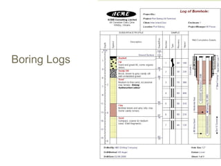
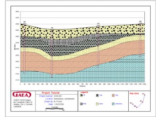
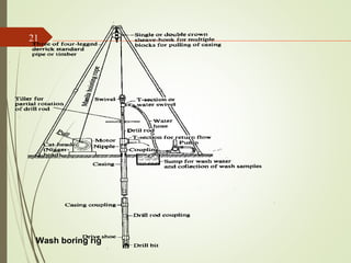
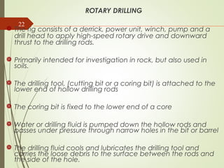
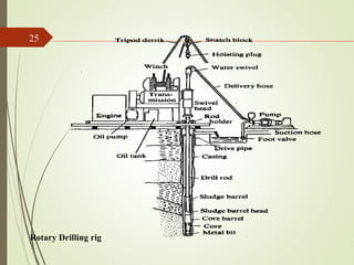
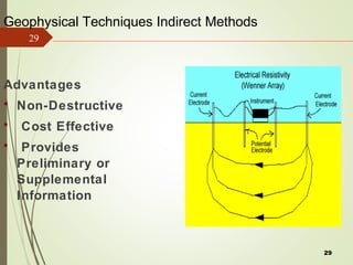
The document discusses various methods for soil exploration including test trenches, auger borings, rotary drilling, and geophysical methods. It also discusses soil sampling techniques for obtaining both disturbed and undisturbed samples. Common stages in a site investigation are described including desk studies, field investigations, laboratory testing, and reporting. The purpose of soil investigations is to determine subsurface soil conditions to influence foundation design and construction.
Bearing capacity of shallow foundations by abhishek sharma ABHISHEK SHARMA
elements you should know about bearing capacity of shallow foundations are included in it. various indian standards are also used. Bearing capacity theories by various researchers are also included. numericals from GATE CE and ESE CE are also included.
A method of testing soils by pressing a cone of standard dimensions into the soil under a known load and measuring the penetration. (extensive investigation and research in construction site).
About Subsurface investigation, Depth of foundation, Significant depth, Types of investigation, Steps involved, Methods of boring, Types of samples and samplers, Core recovery and RQD.
A site investigation simply is the process of the collection of information, the appraisal of data, assessment, and reporting without which the hazards in the ground beneath the site cannot be known
index properties of soil, Those properties of soil which are used in the identification and classification of soil are known as INDEX PROPERTIES
Water content
Specific gravity
In-situ density
Particle size
Consistency
Relative Density
For full course visit our website :
https://www.machenlink.com/course/foundation-engineering/
Description:
This test (IS: 2131 – 1981) is performed in a clean hole, 100 to 150 mm in diameter.
A casing or drilling mud is used to support the sides of the hole.
This test is most commonly used for cohesionless soil which can not be easily sampled.
Useful for determining the relative density and the angle of shear resistance.
It can also be used to determine the unconfined compressive strength of cohesive soil.
The test shall be made,…
At every change in stratum
At intervals not more than 1.5 m
If the number of blows for 150mm exceeds 50 it is taken as a refusal and the test is discontinuous
For full course visit our website :
https://www.machenlink.com/course/foundation-engineering/
Follow #MachenLink
Facebook: https://www.facebook.com/machenLink/
Linkedin: https://www.linkedin.com/company/machenlink/
Twitter: https://twitter.com/MachenLink
VELCITI CONSULTING ENGINEERS (P) LTD was established with the main objective of offering Geo-technical consulting services to the clients on the principles of Quality, Integrity and Speed. Within the short period of inception, the pursuit of excellence has made it possible for the company to be among the field leaders in providing Geo-technical Consulting services
Experimental studies on laterite soil stabilized with cement and aggregateeSAT Journals
Abstract The subgrade must be able to support loads transmitted from pavement structure without excessive deformation under adverse climatic and traffic conditions to increase the life of the pavement. It is a well known fact that, all soils do not possess all the desirable qualities for using it as good quality pavement material. When such soils cannot be replaced, its subgrade performance should be increased by several modification techniques. The place where ground water table is high, the strength of subgrade is adversely affected by moisture infiltration to subgrade and base due to capillary action. The purpose of this paper is to evaluate the use of low contents of cement and aggregate in the modification of a lateritic soil properties concerning the behavior of mixtures to use in the base construction. In the present study an effort is made to obtain the optimum dosage of cement for stabilization of locally available lateritic soil. The study incorporates investigations on basic properties of soil. Then the investigations are carried out to study the effect of addition of 10 mm down aggregates to the soil properties added in addition to the obtained optimum cement content to evaluate the extent of modification on MDD, OMC and CBR of the soil. The experimental investigations shown that there is a tremendous increase in the CBR value of the soil treated with cement-aggregate modification. After conducting all the tests see whether it’s strength is suitable for base coarse. In addition, the field cost analysis is also made to compare the cost of construction for various modifications used. Keywords: lateritic soil 1, Cement 2, Aggregates3, Stabilization4 and CBR5
Una panoramica sulla geofisica. Capitolo 10 - An overview of geophysics. Chap...Franco Mangini
Geofisica planetaria. La struttura interna della terra (ed esempio di interpretazione) - Planetary geophysics. The internal structure of the Earth (and example of interpretation)
1. Site Investgation.pptxDebre Markos University Technology College Departmen...teseraaddis1
Soil Exploration
“ The process of exploring to characterize or define small scale properties of substrata at construction sites is unique to geotechnical engineering.
In other engineering disciplines, material properties are specified during design, or before construction or manufacture, and then controlled to meet the specification. Unfortunately, subsurface properties cannot be specified; they must be deduced through exploration.” Charles H. Dowding (1979).
Class notes of Geotechnical Engineering course I used to teach at UET Lahore. Feel free to download the slide show.
Anyone looking to modify these files and use them for their own teaching purposes can contact me directly to get hold of editable version.
Foundation and its functions
Essential requirements
Sub soil exploration and Site exploration
Methods of site exploration
Settlement of foundations
Causes of failure of foundation and remedial measures
2. 2
Today’s Lecture
Purpose of Soil Exploration
Different methods
1. Test trenches and Pits
2. Auger and Wash Boring
3. Rotary Drilling
4. Geophysical Methods
Soil Sampling (Disturbed and Undisturbed)
3. 3
COMMON STAGES IN SITE INVESTIGATION
Desk Study
Site Reconnaissance
Field Investigations
a) Preliminary Ground Investigation
b) Detailed Ground Investigation
Laboratory Testing
Report Writing
Follow up Investigations during design & construction
Appraisal of performance
4. 4
SOIL INVESTIGATION
Determination of surface and subsurface soil
conditions and features in an area of proposed
construction that may influence the design and
construction and address expected post
construction problems.
SCOPE OF INVESTIGATION
Simple visual examination of soil at the surface or
from shallow test pits.
Detailed study of soil and groundwater to a
reasonable depth (influence zone) by sampling from
bore holes, shafts and audits and in-situ and laboratory
tests.
5. 5PURPOSE OF SOIL INVESTIGATION:
The site investigation provides first hand information for;
Selection of foundation type.
Design of foundations.
Contractors to quote realistic and competitive
tenders.
Planning construction techniques.
Selection of appropriate construction equipment
(especially for excavation and foundations).
Feasibility studies of the site.
Estimating development cost for the site.
Study of environmental impacts of the proposed
construction.
6. 6
Selection of borrow areas for embankments.
Need for any suitable soil improvements.
Requirement of any surface or subsurface drainage.
Selection of the most suitable and economical route for
highways with respect to soil conditions.
Selecting areas (better soil) for engineering structures
where there is flexibility in relocating the structure thus
realizing considerable savings in foundation costs.
The design of extension works to existing structures.
the investigation of the cases where failure has occurred,
to know the causes and design of remedial works.
PURPOSE OF SOIL INVESTIGATION:
6
10. 10
METHODS OF INVESTIGATION
The methods to determine the sequence,
thickness and lateral extent of the soil strata
and, where appropriate the level of
bedrock.
The common methods include
Test pits
Shafts and audits
Boring or drilling
11. 11
Test Pits
The excavation of test pits is a simple and reliable method.
The depth is limited to 4-5m only.
The in-situ conditions are examined visually
It is easy to obtain disturbed and undisturbed samples
Block samples can be cut by hand tools and tube samples can be
taken from the bottom of the pit.
12. 12
12
1
2
3
4
Walls of the test pit indicate four layers (1) Clayey silt (2)
Sandy silt (3) Clean sand (4) Sandy gravel
13. 13
Boring or Drilling
Boring refers to advancing a hole in the ground.
Boring is required for the following:
To obtain representative soil and rock samples for laboratory tests.
To identify the groundwater conditions.
Performance of in-situ tests to assess appropriate soil characteristics.
Some of the common types of boring are as follows
Auger boring
Wash boring
Percussion boring
Rotary drilling
14. 14
Auger Boring
Hand Auger
It is the simplest method of boring used for small projects in soft cohesive
soils.
For hard soil and soil containing gravels boring with hand auger becomes
difficult.
Hand-augered holes can be made upto about 20m depth, although
depth greater than about 8-10m is usually not practical.
The length of the auger blade varies from 0.3-0.5m.
The auger is rotated until it is full of soil, then it is withdrawn to remove the
soil and the soil type present at various depths is noted.
Repeated with drawl of auger for soil removal makes boring difficult
below 8-10m depth.
The soil samples collected in this manner are disturbed samples and can
be used for classification test. Auger boring may not be possible in very
soft clay or coarse sand because the hole tends to collapse when auger
is removed 14
Hand Auger Mechanical Auger
15. 15
a. Helical (worm types) Augers b. Short flight Auger
c. Iwan (posthole) Auger
a
b c
16. 16
Mechanical Auger
Mechanical Auger means power operated augers. The power required
to rotate the auger depends on the type and size of auger and the type
of soil.
Downwards pressure can be applied hydraulically, mechanically or by
dead weight
a
a
b
c d
a. Continuous Flight Auger b. Hallow-stem auger plugged during advancing bore
c. Plug removed and sampler inserted d. Truck mounted auger boring machine
17. 17 The diameter of the flight auger usually is between 75 to 300mm,
although diameters up to 1m and bucket augers up to2m are
available.
Borehole depths up to 50m are possible with continuous-flight
augers.
The most common method is to use continuous flight augers.
Continuous flight augers can be solid stem or hollow stem with
internal diameter of 75-150mm.
Hollow stem augers are used when undisturbed samples are
required. Plug is withdrawn and sampler is lowered down and
driven in to the soil below the auger.
If bed rock is reached drilling can also take place through the
hollow stem.
As the auger acts as a casing it can be used in sand below water
table. The possibility of rising sand in to the stem by hydrostatic
pressure can be avoided by filling the stem with water up to the
water table
17
18. The soil rises to the surface along the helical blades,
obviating the necessity of withdrawal.
They are not suitable for soil bore that require casing,
which demand removal of auger for driving the casing.
The presence of cobbles and boulders create problems
with small-sized augers.
There is a possibility that different soil types may become
mixed as they rise to the surface and it may be difficult
to determine the depths of changes of strata.
Experienced driller can however detect the change of
strata by the change of speed and the sound of drilling.
18
19. 19Wash boring
Water with high pressure pumped through hallow
boring rods is released from narrow holes in a chisel
attach to the lower end of the rods.
The soil is loosened and broken by the water jet and
the up-down moment of the chisel.
The soil particles are carried in suspension to the
surface between the rock and the borehole sites.
The rods are raised and drop for chopping action of
the chisel by means of winch.
Wash boring can be used in most type of soil but the
progress is slow in coarse gravel strata.
19
20. The accurate identification of soil strata is
difficult due to mixing of the material has
they are carried to the surface.
The method is unacceptable for obtaining
soil samples.
It is only used for advancing the borehole to
enable tube sample to be taken or field test
to be carried at the hole bottom.
The advantage is that the soil immediately
below the hole remains relatively un-
disturbed
20
22. 22
ROTARY DRILLING
The rig consists of a derrick, power unit, winch, pump and a
drill head to apply high-speed rotary drive and downward
thrust to the drilling rods.
Primarily intended for investigation in rock, but also used in
soils.
The drilling tool, (cutting bit or a coring bit) is attached to the
lower end of hollow drilling rods
The coring bit is fixed to the lower end of a core
Water or drilling fluid is pumped down the hollow rods and
passes under pressure through narrow holes in the bit or barrel
The drilling fluid cools and lubricates the drilling tool and
carries the loose debris to the surface between the rods and
the side of the hole.
23. The fluid (bentonite slurry) also provides some support to
the sides of the hole if no casing is used
.
There are two forms of rotary drilling, open-hole drilling and
core drilling.
Open- hole drilling, which is generally used in soils and
weak rock, just for advancing the hole
The drilling rods can then be removed to allow tube
samples to be taken or in-situ tests to be carried out.
In core drilling, which is used in rocks and hard clays, the
diamond or tungsten carbide bit cuts an annular hole in
the material and an intact core enters the barrel, to be
removed as a sample. Typical core diameters are 41, 54
and 76mm, but can range up to 165 mm.
23
24. 24
Advantages
The advantage of rotary drilling in soils is that
progress is much faster than with other investigation
methods and disturbance of the soil below the
borehole is slight.
Limitations
The method is not suitable if the soil contains a high
percentage of gravel/cobbles, as they tend to
rotate beneath the bit and are not broken up.
The natural water content of the material is liable to
be increased due to contact with the drilling fluid
26. 26
GEOPHYSICAL METHOD
Although boring and test pits provide definite results but they are time
consuming and expensive.
Subsurface conditions are known only at the bore or test pit location.
The subsurface conditions between the boring need to be interpolated or
estimated.
Geophysical methods are more quick and cheaper.
They provide thorough coverage of the entire area.
The results of Geophysical testing however are less definitive and require
subjective interpretation.
Therefore both methods are important. In case geophysical testing in major
in scope, few borings and sampling will be required for accurate
determination of soil properties.
34. 34
Amount of sampling
Depends upon;
Time constraints
Topography
Cost factors
Reasons for sampling
There are no specific guidelines
Soil Analysis Ch 834
35. 35
Soil Sampling
How many samples do we take?
At least 20 single samples per 10 000m2
must be
taken with an earth boring tool (or spade) and
combined to a mixed sample.
To what depth do we sample?
The usual sampling depth is up to 20 cm in arable
land or 10cm in pasture. Undisturbed soil samples
are obtained with a cutting cylinder with
minimum capacity of 100cm3
.
35
37. Laboratory Testing
Testing by a laboratory accredited to ISO
17025 is an essential part of soil and rock
testing
Competency of staff
Control of test conditions
Accuracy of test measurements
Traceability of measurements to national
standards
Control of test material
Repeatability of results
37
38. Laboratory Testing
Soil and Water testing
Rock Testing
Chemical Testing (for effect on construction materials)
Contamination (Analytical) Testing
38
39. Types of Laboratory Tests
Classification tests
Chemical Tests
Compaction Tests
Shear strength and triaxial tests
Consolidation Tests
Permeability Tests
Specialist Tests
Rock Tests
Contamination Tests
39
40. Structuring the Test Schedule
Design data required and for what purpose
Identification of material characteristics
Identification of contamination levels
Type of sample needed
Minimum mass of sample
Multiple tests on samples
40
40
42. Rock Testing
Classification (moisture, density, porosity,
slake durability)
Point load strength
Uniaxial compressive strength and modulus
Triaxial strength
Permeability
42
42
43. Chemical Tests
To provide design parameters for civil
engineering materials in the ground
pH, sulphate, chloride, carbonate
Organic content and mass loss on
ignition
Special testing (eg SD1)
43
43
44. Compaction Tests
Density/moisture content
relationships
California bearing ratio (CBR)
Moisture condition value tests (MCV)
Maximum/minimum density
Combined relationship testing
44
44
45. Shear Strength and Triaxial Tests
Shear Box
Laboratory vane shear
Quick undrained triaxial test (total stress)
Consolidated undrained triaxial test
(effective stress)
Consolidated drained triaxial test
(effective stress)
Ring shear for residual strength
45
45
This presentation is intended for people specifying:-
geotechnical tests
analytical tests
In the UK accreditation is by external audit undertaken by UKAS.
If a UKAS accredited laboratory is not used – you should audit the laboratory that is used against ISO 17025 before you use it
Data from chemical testing on soils for EA consideration MUST come from MCERTS accredited laboratories
Chemical testing to BS 1377
Contamination testing to EA specified methods
See the ‘AGS Guide to the Selection of Geotechnical Soil Laboratory Testing’ for elaboration
Re-emphasise AGS Guide
NB: It is too late to consider the mass of the sample when scheduling. This should have been addressed at the sampling stage, otherwise some tests will be impossible. eg 3-4kg needed for WAC testing
Why do these tests?
Aid description of materials
Identify expected behaviour of materials
Index to material behaviour and potential use
Practicalities
Ensure sample is suitable for test type
eg
Volume
Type
Disturbed or undisturbed
Why do these tests?
To determine the strength and integrity of rock mass.
Clarify what methods to use, since no British Standard tests
Practicalities
Be clear about the test specification because there is no British Standard (ISRM and ASTM standards are often used)
The first three are routine – the last two are specialist tests
Schedule against specific core depth
Why do these tests?
Age of sample
Issue of conversion (eg sulphur to sulphates)
Practicalities
Refer to BRE Special Digest 1 (NB: must be specific about parameters wanted)
Storage and shelf life of samples
SD1 = BRE document, and ‘analytical methods’ used
Why do these tests?
To obtain information likely to be used very specifically for design and for the construction of earthworks. Therefore quality data is needed that is specific to the construction project and the use to which the data will be put.
Practicalities
Quantity and/or volume of samples
On re-moulded samples need significant sized samples
Specialist tests could include:-
Frost susceptibility
Ring shear
Saturate and moisture content
Chalk crushing value
Why do these tests?
To determine the short term and long term strength of soils for design parameters.
Practicalities
Appropriate samples
Time (NB consolidated triaxial tests take a long time compared to the first 3 tests)
Sample preparation
On undisturbed samples.
If re-moulded then at what moisture content and density
Short and long term tests
‘Effective stress tests’ take longer to do
Why do these tests?
To predict settlement and/or swell
Practicalities
Specify loading stages
What load/unload/re-load cycles
Why do these tests?
To determine the permeability of soils for the design of soakaways, landfill liners, groundwater control, etc
Practicalities
Test conditions
Appropriate sample materials
Time period and test conditions
Market availability
Why do these tests?
To assess contamination in relation to published guidelines to determine
What can be left on site
What treatment might be needed
What to do with material removed from site
Lead by risk assessment and the ultimate use of the site.
Practicalities
Sample size
Containers used
Pretreatment on site
Temperature control
Needs to be scheduled before physical tests (for heath and safety reasons ie to ensure safe to handle)
Total and/or leachate
Check with Project Risk Assessment
Sample pre-treatment and storage
Limits of detection
Seek specialist advice!