Downloaded 336 times
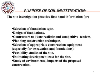
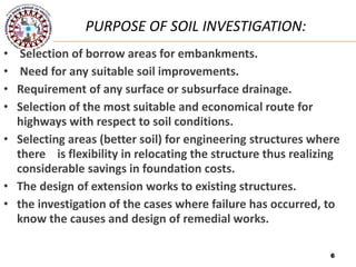
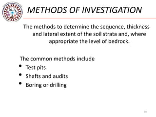
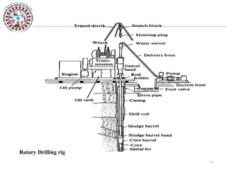

The document discusses various methods for soil exploration including test trenches, auger and wash boring, rotary drilling, and geophysical methods. It describes common stages of site investigation such as desk study, field investigations including preliminary and detailed ground investigation, laboratory testing, and report writing. Various purposes of soil investigation are provided such as selection of foundation type, design of foundations, and planning of construction techniques. Different methods of investigation like test pits, auger boring, wash boring, and rotary drilling are explained. The document also discusses soil sampling methods, laboratory testing, and structuring a test schedule.


![Geotechnical Engineering-II [Lec #9+10: Westergaard Theory]](https://cdn.slidesharecdn.com/ss_thumbnails/9-181020124827-thumbnail.jpg?width=640&height=640&fit=bounds)


![Foundation Eng'g-1, [Lecture Note] on Site Exploration [Chapter One].pptx](https://cdn.slidesharecdn.com/ss_thumbnails/foundationengg-1lecturenoteonsiteexplorationchapterone-251229124058-ecb78644-thumbnail.jpg?width=640&height=640&fit=bounds)


