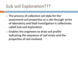
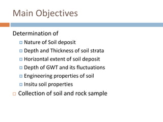
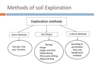
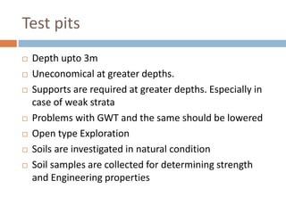
SNPIT & RC,
UMRAKH
Guided By:- Proff. Krunal A. Shah
Subject:- Foundation Engineering
Topic:- Sub Soil Exploration
Nagma Modi
Mrunali Mehta
Prakruti Pathak
Hirvi Vimawala
Sagar Padhiyar
130490106065
130490106064
130490106094
130490106121
140493106015
Prepared by…
SUBSOIL
EXPLORATION
UNIT 1
Sub soil Exploration???
 The process of collection soil data for the
assessment soil properties at a site through series
of laboratory and field investigation is collectively
called Sub-soil Exploration
 Enables the engineers to draw soil profile
indicating the sequence of soil strata and the
properties of soil involved.
Main Objectives
Determination of
 Nature of Soil deposit
 Depth and Thickness of soil strata
 Horizontal extent of soil deposit
 Depth of GWT and its fluctuations
 Engineering properties of soil
 Insitu soil properties
 Collection of soil and rock sample
Introduction
WHAT?
 Attempt at understanding the subsurface conditions such
as:
 Soil and rock profile
 Geological features of the region
 Position and variation of ground water table
 Physical properties of soil and rock
 Contamination, if any
 General data of adjacent structures, hydrological data,
topography, soil maps, seismicity, etc.
 Engineering properties of soil
Introduction
WHY?
 To determine the type of foundation required for
the proposed project at the site, i.e. shallow
foundation or deep foundation.
 To make recommendations regarding the safe
bearing capacity or pile load capacity.
 Ultimately, it is the subsoil that provides the
ultimate support for the structures.
Failures
Leaning Tower of Pisa
and Sinkholes
Introduction
HOW?
 The three important aspect are planning, execution
and report writing.
 Planning
 To minimize cost of explorations and yet give reliable
data.
 Decide on quantity and quality depending on type, size
and importance of project and whether investigation is
preliminary or detailed.
Introduction
 Execution:
 Collection of disturbed and/or
undisturbed samples of
subsurface strata from field.
 Conducting in-situ tests of
subsurface material and obtaining
properties directly or indirectly.
 Study of ground water conditions
and collection of sample for
chemical analysis.
 Geophysical exploration, if
necessary.
 Laboratory testing on samples
Introduction
 Report writing:
 Description of site conditions – topographic features,
hydraulic conditions, existing structures, etc.
supplemented by plans/drawings.
 Description of nature, type and importance of
proposed construction
 Description of field and lab tests carried out.
 Analysis and discussion of data collected
 Preparation of charts, tables, graphs, etc.
 Calculations performed
 Recommendations
Introduction
A complete site investigation will consist of:
 Preliminary work
 Collecting general information and already existing data
such as study of geologic , seismic maps, etc. at or near site.
 Study site history – if previously used as quarry, agricultural
land, industrial unit, etc.
 Site Reconnaissance: Actual site inspection.
 To judge general suitability
 Decide exploration techniques
Introduction
 Exploration
 Preliminary Investigations: Exploratory borings or shallow
test pits, representative sampling, geophysical
investigations, etc
 Detailed Investigations: Deep boreholes, extensive
sampling, in-situ testing, lab testing, etc.
 Depth and spacing: In general, depth of investigation
should be such that any/all strata that are likely to
experience settlement or failure due to loading. Spacing
depends upon degree of variation of surface topography
and subsurface strata in horizontal direction. Refer to Alam
Singh.
14
Boring Logs
15
Methods of soil Exploration
Exploration methods
Direct Methods Semi Direct In Direct Methods
Test pits, Trial
pits, Trenches
Borings
•Auger
•Auger and shell
•Wash Boring
•Percussion drilling
•Rotary Drilling
Sounding or
penetration
Tests and
Geophysical
methods
Test pits
 Depth upto 3m
 Uneconomical at greater depths.
 Supports are required at greater depths. Especially in
case of weak strata
 Problems with GWT and the same should be lowered
 Open type Exploration
 Soils are investigated in natural condition
 Soil samples are collected for determining strength
and Engineering properties
18
1
2
3
4
Walls of the test pit indicate four layers (1) Clayey silt (2)
Sandy silt (3) Clean sand (4) Sandy gravel
Stratigraphy and Finds
Layer Soil Soil Colour Finds Chronology
L1 Sandy soil Gray 7.5YR 5/1 Modern Rubbish (filled soil) 1980s
L2 Sandy soil Pinkish white 7.5YR 8/2 Modern rubbish (filled soil) 1980s
L3 Sandy soil Reddish yellow 7.5YR 7/6 Modern rubbish (filled soil) 1980s
L4 Sandy soil Gray 7.5YR 6/1 Modern rubbish (filled soil) 1980s
L5 Loamy soil Reddish yellow 5YR 6/6 Nil (original decomposed soil)
L6 Loamy soil Reddish yellow 5YR 6/8 Nil (original decomposed soil)
L7 Loamy soil, with
some
decomposed
bed rock texture
Light red 2.5YR 6/8 Nil (original decomposed soil)
Test Pit Wall Photograph
Western Wall Section
Test Pit Wall Drawing
Western Wall Section Drawing
Excavated test pit
Boring
Drilling a hole into the soil strata upto specified
depth is known as boring
1. Auger boring
2. Auger and shell boring
3. Wash boring
4. Percussion drilling
5. Rotary drilling
Auger Boring
 Drilling is made using a device called Soil Auger
 Power driven (upto 3 to 5m) and Hand operated
(Greater than 5m)
 Advancement is made by drilling the auger by
simultaneous rotating and pressing it into the soil
 Dry and unsupported bore holes
 When the auger gets filled with soil same, it is
taken out and the soil sample collected
Soil augers
Auger and Shell Boring
 Casing is provided in case of weak strata
 First the casing is driven and then the auger
 Boring rig is used for power driving (hand rig for depth
upto 25 m)
 Soft rocks are broken using chisel bits
 Sand pumps are used in the case of sandy soils.
Disadvantage:
 Whenever the casing is to be extended, the auger has
to be withdrawn which hinders the quick progress of
the work.
Wash Boring
 Below GWT. May not be used for soils mixed with gravel and
boulders
 Initially, the hole is advanced for a short depth by using an
auger.
 Then a casing pipe is pushed in and driven with a drop
weight. The driving may be with the aid of power.
 A hollow drill bit is screwed to a hollow drill rod connected to
a rope passing over a pulley and supported by a tripod.
 Water jet under pressure is forced through the rod and the
bit into the hole.
 This loosens the soil at the lower end and forces the soil-
water suspension upwards along the annular surface between
the rod and the side of the hole
 This suspension is collected in a settling tank.
 Soil particles are allowed to settle down and water is
allowed to overflow into a sump which is then
recirculated
 Very disturbed sample is obtained. Hence cannot be
used for determining engineering properties.
 whenever a soil sample is required, the chopping bit is
to be replaced by a sampler.
 The change of the rate of progress and change of
colour of wash water indicate changes in soil strata.
Typical set up for Wash boring
Percussion Drilling
 A heavy drill bit called ‘churn bit’ is suspended from a
drill rod or a cable and is driven by repeated blows.
 Water is added to facilitate the breaking of stiff soil or
rock.
 The slurry of the pulverised material is bailed out at
intervals.
Disadvantages
 Cannot be used in loose sand and is slow in plastic clay.
 The formation gets badly disturbed by impact.
Rotary Drilling
 Suitable for rock formations.
 A drill bit, fixed to the lower end of a drill rod, is rotated
 by power while being kept in firm contact with the hole.
 Drilling fluid or bentonite slurry is used under pressure
which brings up the cuttings to the surface.
 Even rock cores may be obtained by using suitable
diamond drill bits.
Disadvantage
 Not used in porous deposits as the consumption of drilling
fluid would be high.
Indirect methods
 Sounding or penetration Tests and
 Geophysical methods
SPT “IS: 2131-1986—
Standard Penetration Test”.
 Generally used for cohesionless soils
 To determine relative density , angle of shearing
resistance, UCC
 A bore hole is made using drilling tools and a
hammer of weight 63.5 falling from the height of
750 mm at the rate of 30 blows/minute
 After reaching the specified depth, the drilling tool
is replaced by a split spoon sampler to collect soil
sample.
 First 150 mm penetration is taken as seating
drive and the no. of blows required for that
penetration is discarded
 No of blows required for next 300mm
penetration after seating drive is taken as
standard penetration number (N)
 No of blows greater than 50 are taken as
refusal and the test is discontinued
 Corrections are applied to the observed N
value
Correction to N value
 Dilatancy Correction
 Overburden correction
Of these, overburden correction is applied first
and to that corrected value, dilatancy Correction is
applied
Dilatancy Correction
Due to the presence of fine sand and silt below
the water table, negative pore pressure develops
which increases, the observed N value. Hence
correction is applied. (If N’<15 or N=15 , N’ = N)
Over burden correction
 Soils having the same relative density will show higher
N value at greater depth due to presence of over
burden.
 Cohesionless soils are greatly affected by confining
pressure. Hence N value is corrected .σ <=280 kN/m2
SPT correlations for cohesionless soil
SPT correlations for Clays
 This method is also used to skin friction values which is
used to determine the length of the piles
 The cone is pushed only by thrust and not by driving
 In order to find out the cone resistance , the cone alone
is pushed
 Later the cone and sleeve is pushed together to find
out the combined frictional and point resistance of the
cone.
 Hydraulic gauges are used for measuring pressure
developed
 Frictional resistance = Combined resistance –
Cone resistance
 Modified Cone penetrometer is known as Refined
Dutch Cone
 Cone penetration resistance is denoted as qc in
kN/m2
 Unlike SPT, this method is also suitable for clayey
deposits
 Unsuitable for gravels and dense sand. For such
soil dynamic Cone penetration is used
Point cone resistance Vs SPT
Correlation
Type of Soil Qc (kN/m2) Vs
SPT ‘N’
Gravel 800 to 1000
Sands 500 to 600
Silty sands 300 to 400
Silts and clayey silts 200
Cone and Friction assembly for SCPT
Cone used for SCPT
Typical Test Set up for SCPT
• The stratification of soils and rocks can be determined by
geophysical methods of exploration which messures changes in
certain physical characteristics of these materials,for example
density,magnetism,electrical resistivity,etc.
The following two geophysical methods are commonly used:
(i)Seismic refraction method
(ii)Electrical resistivity method
(i)Seismic Refraction Method:
The seismic refraction method is based on the principal that
seismic waves have different velocities in different types of soil.
The seismic refraction method is more suited to shallow exploration
for civil engineering purposes.
Geophysical methods:
The electrical resistivity d is given by
ℓ=2*3.14*D*V/I
ℓ=mean resistivity (ohm/m)
D=distance between electrodes (m)
V =potential drop between two inner electrodes (volts)
I=current applied between two outer electrodes
(Amperes)
Limitations:
(i)The methods are capable of detecting only the strata
having different electrical resistivity.
(ii)The services of an expert in the field are needed.
Sub soil exploration

Sub soil exploration

  • 1.
    SNPIT & RC, UMRAKH GuidedBy:- Proff. Krunal A. Shah Subject:- Foundation Engineering Topic:- Sub Soil Exploration Nagma Modi Mrunali Mehta Prakruti Pathak Hirvi Vimawala Sagar Padhiyar 130490106065 130490106064 130490106094 130490106121 140493106015 Prepared by…
  • 2.
  • 3.
    Sub soil Exploration??? The process of collection soil data for the assessment soil properties at a site through series of laboratory and field investigation is collectively called Sub-soil Exploration  Enables the engineers to draw soil profile indicating the sequence of soil strata and the properties of soil involved.
  • 4.
    Main Objectives Determination of Nature of Soil deposit  Depth and Thickness of soil strata  Horizontal extent of soil deposit  Depth of GWT and its fluctuations  Engineering properties of soil  Insitu soil properties  Collection of soil and rock sample
  • 5.
    Introduction WHAT?  Attempt atunderstanding the subsurface conditions such as:  Soil and rock profile  Geological features of the region  Position and variation of ground water table  Physical properties of soil and rock  Contamination, if any  General data of adjacent structures, hydrological data, topography, soil maps, seismicity, etc.  Engineering properties of soil
  • 6.
    Introduction WHY?  To determinethe type of foundation required for the proposed project at the site, i.e. shallow foundation or deep foundation.  To make recommendations regarding the safe bearing capacity or pile load capacity.  Ultimately, it is the subsoil that provides the ultimate support for the structures.
  • 7.
  • 8.
    Leaning Tower ofPisa and Sinkholes
  • 9.
    Introduction HOW?  The threeimportant aspect are planning, execution and report writing.  Planning  To minimize cost of explorations and yet give reliable data.  Decide on quantity and quality depending on type, size and importance of project and whether investigation is preliminary or detailed.
  • 10.
    Introduction  Execution:  Collectionof disturbed and/or undisturbed samples of subsurface strata from field.  Conducting in-situ tests of subsurface material and obtaining properties directly or indirectly.  Study of ground water conditions and collection of sample for chemical analysis.  Geophysical exploration, if necessary.  Laboratory testing on samples
  • 11.
    Introduction  Report writing: Description of site conditions – topographic features, hydraulic conditions, existing structures, etc. supplemented by plans/drawings.  Description of nature, type and importance of proposed construction  Description of field and lab tests carried out.  Analysis and discussion of data collected  Preparation of charts, tables, graphs, etc.  Calculations performed  Recommendations
  • 12.
    Introduction A complete siteinvestigation will consist of:  Preliminary work  Collecting general information and already existing data such as study of geologic , seismic maps, etc. at or near site.  Study site history – if previously used as quarry, agricultural land, industrial unit, etc.  Site Reconnaissance: Actual site inspection.  To judge general suitability  Decide exploration techniques
  • 13.
    Introduction  Exploration  PreliminaryInvestigations: Exploratory borings or shallow test pits, representative sampling, geophysical investigations, etc  Detailed Investigations: Deep boreholes, extensive sampling, in-situ testing, lab testing, etc.  Depth and spacing: In general, depth of investigation should be such that any/all strata that are likely to experience settlement or failure due to loading. Spacing depends upon degree of variation of surface topography and subsurface strata in horizontal direction. Refer to Alam Singh.
  • 14.
  • 15.
  • 16.
    Methods of soilExploration Exploration methods Direct Methods Semi Direct In Direct Methods Test pits, Trial pits, Trenches Borings •Auger •Auger and shell •Wash Boring •Percussion drilling •Rotary Drilling Sounding or penetration Tests and Geophysical methods
  • 17.
    Test pits  Depthupto 3m  Uneconomical at greater depths.  Supports are required at greater depths. Especially in case of weak strata  Problems with GWT and the same should be lowered  Open type Exploration  Soils are investigated in natural condition  Soil samples are collected for determining strength and Engineering properties
  • 18.
    18 1 2 3 4 Walls of thetest pit indicate four layers (1) Clayey silt (2) Sandy silt (3) Clean sand (4) Sandy gravel
  • 19.
    Stratigraphy and Finds LayerSoil Soil Colour Finds Chronology L1 Sandy soil Gray 7.5YR 5/1 Modern Rubbish (filled soil) 1980s L2 Sandy soil Pinkish white 7.5YR 8/2 Modern rubbish (filled soil) 1980s L3 Sandy soil Reddish yellow 7.5YR 7/6 Modern rubbish (filled soil) 1980s L4 Sandy soil Gray 7.5YR 6/1 Modern rubbish (filled soil) 1980s L5 Loamy soil Reddish yellow 5YR 6/6 Nil (original decomposed soil) L6 Loamy soil Reddish yellow 5YR 6/8 Nil (original decomposed soil) L7 Loamy soil, with some decomposed bed rock texture Light red 2.5YR 6/8 Nil (original decomposed soil) Test Pit Wall Photograph Western Wall Section Test Pit Wall Drawing Western Wall Section Drawing
  • 20.
  • 21.
    Boring Drilling a holeinto the soil strata upto specified depth is known as boring 1. Auger boring 2. Auger and shell boring 3. Wash boring 4. Percussion drilling 5. Rotary drilling
  • 22.
    Auger Boring  Drillingis made using a device called Soil Auger  Power driven (upto 3 to 5m) and Hand operated (Greater than 5m)  Advancement is made by drilling the auger by simultaneous rotating and pressing it into the soil  Dry and unsupported bore holes  When the auger gets filled with soil same, it is taken out and the soil sample collected
  • 23.
  • 24.
    Auger and ShellBoring  Casing is provided in case of weak strata  First the casing is driven and then the auger  Boring rig is used for power driving (hand rig for depth upto 25 m)  Soft rocks are broken using chisel bits  Sand pumps are used in the case of sandy soils. Disadvantage:  Whenever the casing is to be extended, the auger has to be withdrawn which hinders the quick progress of the work.
  • 25.
    Wash Boring  BelowGWT. May not be used for soils mixed with gravel and boulders  Initially, the hole is advanced for a short depth by using an auger.  Then a casing pipe is pushed in and driven with a drop weight. The driving may be with the aid of power.  A hollow drill bit is screwed to a hollow drill rod connected to a rope passing over a pulley and supported by a tripod.  Water jet under pressure is forced through the rod and the bit into the hole.  This loosens the soil at the lower end and forces the soil- water suspension upwards along the annular surface between the rod and the side of the hole
  • 26.
     This suspensionis collected in a settling tank.  Soil particles are allowed to settle down and water is allowed to overflow into a sump which is then recirculated  Very disturbed sample is obtained. Hence cannot be used for determining engineering properties.  whenever a soil sample is required, the chopping bit is to be replaced by a sampler.  The change of the rate of progress and change of colour of wash water indicate changes in soil strata.
  • 27.
    Typical set upfor Wash boring
  • 29.
    Percussion Drilling  Aheavy drill bit called ‘churn bit’ is suspended from a drill rod or a cable and is driven by repeated blows.  Water is added to facilitate the breaking of stiff soil or rock.  The slurry of the pulverised material is bailed out at intervals. Disadvantages  Cannot be used in loose sand and is slow in plastic clay.  The formation gets badly disturbed by impact.
  • 30.
    Rotary Drilling  Suitablefor rock formations.  A drill bit, fixed to the lower end of a drill rod, is rotated  by power while being kept in firm contact with the hole.  Drilling fluid or bentonite slurry is used under pressure which brings up the cuttings to the surface.  Even rock cores may be obtained by using suitable diamond drill bits. Disadvantage  Not used in porous deposits as the consumption of drilling fluid would be high.
  • 32.
    Indirect methods  Soundingor penetration Tests and  Geophysical methods
  • 33.
    SPT “IS: 2131-1986— StandardPenetration Test”.  Generally used for cohesionless soils  To determine relative density , angle of shearing resistance, UCC  A bore hole is made using drilling tools and a hammer of weight 63.5 falling from the height of 750 mm at the rate of 30 blows/minute  After reaching the specified depth, the drilling tool is replaced by a split spoon sampler to collect soil sample.
  • 34.
     First 150mm penetration is taken as seating drive and the no. of blows required for that penetration is discarded  No of blows required for next 300mm penetration after seating drive is taken as standard penetration number (N)  No of blows greater than 50 are taken as refusal and the test is discontinued  Corrections are applied to the observed N value
  • 36.
    Correction to Nvalue  Dilatancy Correction  Overburden correction Of these, overburden correction is applied first and to that corrected value, dilatancy Correction is applied
  • 37.
    Dilatancy Correction Due tothe presence of fine sand and silt below the water table, negative pore pressure develops which increases, the observed N value. Hence correction is applied. (If N’<15 or N=15 , N’ = N)
  • 38.
    Over burden correction Soils having the same relative density will show higher N value at greater depth due to presence of over burden.  Cohesionless soils are greatly affected by confining pressure. Hence N value is corrected .σ <=280 kN/m2
  • 39.
    SPT correlations forcohesionless soil
  • 40.
  • 42.
     This methodis also used to skin friction values which is used to determine the length of the piles  The cone is pushed only by thrust and not by driving  In order to find out the cone resistance , the cone alone is pushed  Later the cone and sleeve is pushed together to find out the combined frictional and point resistance of the cone.  Hydraulic gauges are used for measuring pressure developed
  • 43.
     Frictional resistance= Combined resistance – Cone resistance  Modified Cone penetrometer is known as Refined Dutch Cone  Cone penetration resistance is denoted as qc in kN/m2  Unlike SPT, this method is also suitable for clayey deposits  Unsuitable for gravels and dense sand. For such soil dynamic Cone penetration is used
  • 44.
    Point cone resistanceVs SPT Correlation Type of Soil Qc (kN/m2) Vs SPT ‘N’ Gravel 800 to 1000 Sands 500 to 600 Silty sands 300 to 400 Silts and clayey silts 200
  • 45.
    Cone and Frictionassembly for SCPT
  • 46.
  • 47.
    Typical Test Setup for SCPT
  • 48.
    • The stratificationof soils and rocks can be determined by geophysical methods of exploration which messures changes in certain physical characteristics of these materials,for example density,magnetism,electrical resistivity,etc. The following two geophysical methods are commonly used: (i)Seismic refraction method (ii)Electrical resistivity method (i)Seismic Refraction Method: The seismic refraction method is based on the principal that seismic waves have different velocities in different types of soil. The seismic refraction method is more suited to shallow exploration for civil engineering purposes. Geophysical methods:
  • 51.
    The electrical resistivityd is given by ℓ=2*3.14*D*V/I ℓ=mean resistivity (ohm/m) D=distance between electrodes (m) V =potential drop between two inner electrodes (volts) I=current applied between two outer electrodes (Amperes) Limitations: (i)The methods are capable of detecting only the strata having different electrical resistivity. (ii)The services of an expert in the field are needed.

Editor's Notes