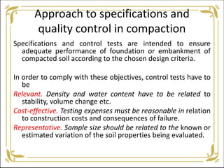
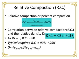
Field Compaction Methods
Prof. S.G.Teggi
Assistant Professor
SRES SCOE Kopargaon
Approach to specifications and
quality control in compaction
Specifications and control tests are intended to ensure
adequate performance of foundation or embankment of
compacted soil according to the chosen design criteria.
In order to comply with these objectives, control tests have to
be
Relevant. Density and water content have to be related to
stability, volume change etc.
Cost-effective. Testing expenses must be reasonable in relation
to construction costs and consequences of failure.
Representative. Sample size should be related to the known or
estimated variation of the soil properties being evaluated.
Suitability of soils as fills
• When high strength and low compressibility are required, but
seepage and erodability are not significant, coarse granular fills are
most suitable.
• As impermeable liners for canals or as core material for dams,
clayey gravels and poorly graded gravel-sand-clay mixtures are
ranked the highest.
• Silty soils and dispersive clays, even if compacted well, are
vulnerable to erosion by surface runoff or internal seepage.
• Soils containing organic matter are unsuitable for engineering fills,
because of their high compressibility under loads and large volume
changes due to environmental influences.
Compaction control tests
• Compaction control tests are essential to check
whether the objectives of compaction are
achieved.
• It is difficult to check the objectives directly and
properties strength and compressibility are
assessed indirectly.
• Control tests in terms of water content, density,
penetration resistance are conducted.
Compaction Control Procedures
Laboratory tests are conducted on samples of the proposed
borrow materials to define the properties required for
design.
• After the earth structure is designed, the compaction
specifications written.
• Field compaction control tests are specified, and the results
of these become the standard for controlling the project.
• These specifications are expected to ensure an expected
level of performance (in terms of shear strength,
compressibility, permeability which are related to bearing
capacity, settlements and drainage and seepage etc)
Types of Specifications
(1) End-product specifications
This specification is used for most highways and building
foundation, as long as the contractor is able to obtain the
specified relative compaction, how he obtains it doesn’t
matter, nor does the equipment he uses.
(2) Method specifications
The type and weight of roller, the number of passes of that
roller, as well as the lift thickness are specified. A maximum
allowable size of material may also be specified.
It is typically used for large compaction project.
Relative Compaction (R.C.)
• Relative compaction or percent compaction
• Correlation between relative compaction(R.C.)
and the relative density Dr
• As Dr = 0, R.C. is 80
• Typical required R.C. = 90% ~ 95%
• Dr=(emax-e)/(emax - emin)
Determine the Relative Compaction in the Field
Where and When
• First, the test site is selected, it should be representative or
typical of the compacted lift and borrow material.
• Typical specifications call for a new field test for every 1000
to 2000m2 or so, or when the borrow material changes
significantly.
• It is also advisable to make the field test at least one or two
compacted lifts below the already compacted ground
surface, especially when sheep foot rollers are used or in
granular soils.
Experience and engineering judgment suggest the approximate
minimum numbers of field density and moisture content tests
are as follows
Determination of Field Density
A few methods are as follows
Destructive methods
•Core cutting method IS 2720 (Part 29)
•Sand replacement method IS 2720 (Part 28)
•Volumenometer method
•Rubber-balloon method
•Proctor-needle method
Non- destructive methods
•Nuclear gauge method
•Impact Tester
Core cutting method
• A steel tubular cutter of 107mm dia X 125mm is driven into
compacted layer using rammer. The sample is retrieved and bulk
density is measured as well as water content is determined.
Sand replacement method
• A hole of 15cm dia is made in the layer in which the test needs to
be conducted. The soil is removed carefully and collected to
determine the weight as well as water content. To determine the
volume of the hole, a known amount of calibrated sand is used.
Based on the relationship between index properties such as bulk
density, dry density and volume, the bulk density of Insitu soil can
be calculated.
Volumenometer method
• Useful for clayey soils. A soil of about 295cc is taken out
from the compacted layer of embankment. It is quoted
with wax and reweighed. The actual volume of the sample
is known by immersing it in volumenometer. A sample cut
from the specimen can be used for water content
determination.
Rubber balloon method (IS 2720)
• In this method, a rubber balloon is used to measure volume
of the hole made in the compacted layer. The volume of the
hole is found out from the difference between the initial
and final water levels in the gas cylinder.
Difficulties with Destructive Methods
The measuring error is mainly from the determination of the volume
of the excavated material.
For example,
• For the sand cone method, the vibration from nearby working
equipment will increase the density of the sand in the hole, which
will gives a larger hole volume and a lower field density.
• If the compacted fill is gravel or contains large gravel particles. Any
kind of unevenness in the walls of the hole causes a significant error
in the balloon method.
• If the soil is coarse sand or gravel, none of the liquid methods works
well, unless the hole is very large and a polyethylene sheet is used
to contain the water or oil.
Non-Destructive methods
Principles
Density
• The Gamma radiation is scattered by the soil particles
and the amount of scatter is proportional to the total
density of the material.
• The Gamma radiation is typically provided by the
radium or a radioactive isotope of cesium.
Water content
• The water content can be determined based on the
neutron scatter by hydrogen atoms. Typical neutron
sources are americium-beryllium isotopes
.
Thank You

Field compaction methods

  • 1.
    Field Compaction Methods Prof.S.G.Teggi Assistant Professor SRES SCOE Kopargaon
  • 23.
    Approach to specificationsand quality control in compaction Specifications and control tests are intended to ensure adequate performance of foundation or embankment of compacted soil according to the chosen design criteria. In order to comply with these objectives, control tests have to be Relevant. Density and water content have to be related to stability, volume change etc. Cost-effective. Testing expenses must be reasonable in relation to construction costs and consequences of failure. Representative. Sample size should be related to the known or estimated variation of the soil properties being evaluated.
  • 24.
    Suitability of soilsas fills • When high strength and low compressibility are required, but seepage and erodability are not significant, coarse granular fills are most suitable. • As impermeable liners for canals or as core material for dams, clayey gravels and poorly graded gravel-sand-clay mixtures are ranked the highest. • Silty soils and dispersive clays, even if compacted well, are vulnerable to erosion by surface runoff or internal seepage. • Soils containing organic matter are unsuitable for engineering fills, because of their high compressibility under loads and large volume changes due to environmental influences.
  • 25.
    Compaction control tests •Compaction control tests are essential to check whether the objectives of compaction are achieved. • It is difficult to check the objectives directly and properties strength and compressibility are assessed indirectly. • Control tests in terms of water content, density, penetration resistance are conducted.
  • 26.
    Compaction Control Procedures Laboratorytests are conducted on samples of the proposed borrow materials to define the properties required for design. • After the earth structure is designed, the compaction specifications written. • Field compaction control tests are specified, and the results of these become the standard for controlling the project. • These specifications are expected to ensure an expected level of performance (in terms of shear strength, compressibility, permeability which are related to bearing capacity, settlements and drainage and seepage etc)
  • 27.
    Types of Specifications (1)End-product specifications This specification is used for most highways and building foundation, as long as the contractor is able to obtain the specified relative compaction, how he obtains it doesn’t matter, nor does the equipment he uses. (2) Method specifications The type and weight of roller, the number of passes of that roller, as well as the lift thickness are specified. A maximum allowable size of material may also be specified. It is typically used for large compaction project.
  • 28.
    Relative Compaction (R.C.) •Relative compaction or percent compaction • Correlation between relative compaction(R.C.) and the relative density Dr • As Dr = 0, R.C. is 80 • Typical required R.C. = 90% ~ 95% • Dr=(emax-e)/(emax - emin)
  • 29.
    Determine the RelativeCompaction in the Field Where and When • First, the test site is selected, it should be representative or typical of the compacted lift and borrow material. • Typical specifications call for a new field test for every 1000 to 2000m2 or so, or when the borrow material changes significantly. • It is also advisable to make the field test at least one or two compacted lifts below the already compacted ground surface, especially when sheep foot rollers are used or in granular soils.
  • 30.
    Experience and engineeringjudgment suggest the approximate minimum numbers of field density and moisture content tests are as follows
  • 31.
    Determination of FieldDensity A few methods are as follows Destructive methods •Core cutting method IS 2720 (Part 29) •Sand replacement method IS 2720 (Part 28) •Volumenometer method •Rubber-balloon method •Proctor-needle method Non- destructive methods •Nuclear gauge method •Impact Tester
  • 33.
    Core cutting method •A steel tubular cutter of 107mm dia X 125mm is driven into compacted layer using rammer. The sample is retrieved and bulk density is measured as well as water content is determined. Sand replacement method • A hole of 15cm dia is made in the layer in which the test needs to be conducted. The soil is removed carefully and collected to determine the weight as well as water content. To determine the volume of the hole, a known amount of calibrated sand is used. Based on the relationship between index properties such as bulk density, dry density and volume, the bulk density of Insitu soil can be calculated.
  • 34.
    Volumenometer method • Usefulfor clayey soils. A soil of about 295cc is taken out from the compacted layer of embankment. It is quoted with wax and reweighed. The actual volume of the sample is known by immersing it in volumenometer. A sample cut from the specimen can be used for water content determination. Rubber balloon method (IS 2720) • In this method, a rubber balloon is used to measure volume of the hole made in the compacted layer. The volume of the hole is found out from the difference between the initial and final water levels in the gas cylinder.
  • 36.
    Difficulties with DestructiveMethods The measuring error is mainly from the determination of the volume of the excavated material. For example, • For the sand cone method, the vibration from nearby working equipment will increase the density of the sand in the hole, which will gives a larger hole volume and a lower field density. • If the compacted fill is gravel or contains large gravel particles. Any kind of unevenness in the walls of the hole causes a significant error in the balloon method. • If the soil is coarse sand or gravel, none of the liquid methods works well, unless the hole is very large and a polyethylene sheet is used to contain the water or oil.
  • 37.
    Non-Destructive methods Principles Density • TheGamma radiation is scattered by the soil particles and the amount of scatter is proportional to the total density of the material. • The Gamma radiation is typically provided by the radium or a radioactive isotope of cesium. Water content • The water content can be determined based on the neutron scatter by hydrogen atoms. Typical neutron sources are americium-beryllium isotopes
  • 39.