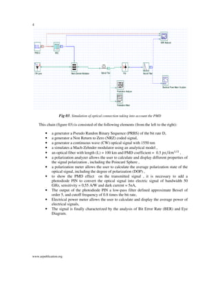
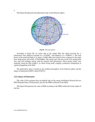
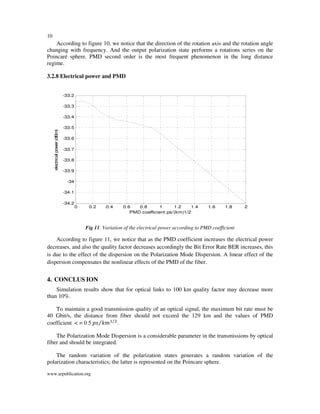
Polarization Mode Dispersion (PMD) is a factor which limits the bit rate of the optical transmissions. The PMD is such an effect which is time broadening due to the dependence of the group velocity to the signal polarization. The deformation effects of the impulses become considerable from 40 Gb/s. This paper, we reviews the degrade PMD effect in the telecommunications optical connections to high bit rate, due to the evolution of quality factor (Q) according to the fiber length, bit rate and PMD coefficient , well as the impact PMD on the degree of polarization and electrical power, we discuss also the representation of the polarization state and PMD vector on the Poincare sphere.
This document summarizes dispersion management in optical fiber communication. It discusses the basic components of an optical fiber including the core, cladding, buffer, and jacket. It also describes optical transmitters such as lasers and LEDs, as well as optical receivers such as photo detectors. The document outlines the main types of dispersion in fibers including material dispersion, waveguide dispersion, and polarization mode dispersion. It compares Gaussian and super Gaussian pulses and how super Gaussian pulses can reduce dispersion, especially at higher data transmission rates. In conclusion, the document provides a basic overview of optical fiber communication and dispersion management techniques.
Dispersion Compensation Techniques for Optical Fiber CommunicationAmit Raikar
This document discusses dispersion in optical fiber communication systems and various techniques to compensate for it, including dispersion compensating fibers, fiber Bragg gratings, electronic dispersion compensation, digital filters, and optical phase conjugation. Dispersion increases pulse spreading and affects signal quality. These techniques help reduce dispersion to improve transmission over long distances. The document compares the advantages and disadvantages of each technique.
Polarization mode dispersion (PMD) is a form of dispersion in optical fibers where the two polarization states of light travel at slightly different velocities, causing the optical signal to spread randomly. PMD occurs due to imperfections and asymmetries in the glass fiber core that introduce small refractive index variations between the two polarization states, known as birefringence. Low levels of PMD cause no distortion or bit errors in the digital signal, while high PMD can disperse the light wave enough to significantly distort the digital signal and cause multiple transmission errors. PMD is measured statistically along the fiber as the amount of dispersion between the two polarization states can vary randomly at different points.
Attenuation is
the reduction of signal strength or light power over the length of
the light-carrying medium. As the light signal travels down the fiber,
it losses power or attenuates.
This document discusses different types of dispersion in optical fibers, including modal dispersion, material dispersion, waveguide dispersion, and polarization mode dispersion. It defines important terms related to dispersion like group velocity and group delay. It also examines how dispersion causes pulse broadening over distance as different wavelengths within a pulse propagate at different speeds through the fiber. Finally, it compares the dispersion characteristics of different fiber types like dispersion shifted and flattened fibers which are designed to reduce dispersion effects.
Mesuarement of the attenuatuion of the optical fiber ieee format mohamud mire
This document discusses the measurement of attenuation in optical fibers. It begins by defining attenuation and describing the various factors that cause it, including absorption, scattering, and bending. It then provides details on the basic structure of an optical fiber, including the core and cladding. It also describes the two main types of optical fibers: multimode and single-mode. The advantages of optical fibers are listed as well. The document is intended to investigate the characteristics and factors causing attenuation in optical fiber systems.
Disclosed is an optical fiber comprising a center core which forms a passageway for transmitting
optical signals and has a refractive index N1, and a cladding which encloses the center core and
has a refractive index N0. The optical fiber further comprises an upper core, which has a
distribution of refractive indices increased starting from a refractive index N2 (>N0) at its outer
circumference to the refractive index N1 at its internal circumference, and a minutely depressed
refractive index region, which is interposed between said upper core and cladding and has a
refractive index N3. The refractive index N3 is lower than the refractive index N0.
This document provides an overview of non-linear fiber optics. It discusses how the refractive index of an optical fiber becomes dependent on optical intensity at higher powers, leading to non-linear propagation effects. Key topics covered include Kerr non-linearity, frequency mixing via the third-order susceptibility, derivation of the non-linear Schrodinger equation, and implications for wavelength division multiplexing transmission. The document explains that non-linear effects can be easily observed at low powers in fibers due to the high intensity confinement over long interaction lengths.
IJRET : International Journal of Research in Engineering and Technology is an international peer reviewed, online journal published by eSAT Publishing House for the enhancement of research in various disciplines of Engineering and Technology. The aim and scope of the journal is to provide an academic medium and an important reference for the advancement and dissemination of research results that support high-level learning, teaching and research in the fields of Engineering and Technology. We bring together Scientists, Academician, Field Engineers, Scholars and Students of related fields of Engineering and Technology
This document discusses various sources of signal attenuation and distortion that occur as optical signals propagate through optical fibers. It describes the primary mechanisms of signal attenuation as material absorption, scattering, and bending losses. Material absorption includes intrinsic absorption from the fiber material and extrinsic absorption from impurities. Scattering results from refractive index variations within the fiber. Signal distortion is caused by chromatic dispersion, polarization mode dispersion, and intermodal dispersion. The document outlines techniques to reduce dispersion, such as dispersion-shifted fibers, non-zero dispersion-shifted fibers, and dispersion-compensating fibers.
(1) Optical signals propagating through optical fiber experience attenuation and dispersion, which degrade the signal.
(2) Attenuation reduces the signal power as it travels along the fiber and limits the maximum transmission distance. The primary attenuation mechanisms are absorption and scattering.
(3) Dispersion causes different frequency components of the signal to travel at different velocities, resulting in signal broadening and limiting transmission capacity. The primary dispersion mechanisms are material dispersion, waveguide dispersion, and polarization mode dispersion.
Mode Field Diameter (MFD) is a measure of light intensity in the core of a single mode fiber. It is traditionally defined as the width where intensity falls to 1/e of its peak value, but standards now define it via the Petermann II integral of the far-field intensity distribution. MFD represents the effective area of light propagation in both the core and cladding. It provides important information about a cable's performance and impacts from bending or improper source-fiber coupling that could lead to excessive loss. MFD is tested using an optical time domain reflectometer to obtain the far-field profile and calculate the Petermann II integral to determine the MFD value.
Unit 2 Attenuation bending loss- core cladding lossesjosephin Shermila
The document discusses two types of bending loss that can occur in optical fibers: macroscopic bending, which occurs when a fiber is bent with a radius larger than the core radius, and microbending, which is minimized by using a protective jacket around the fiber. It also mentions several factors that contribute to bending loss, such as the attenuation constant, radius of curvature, number of guided modes, and core and cladding properties between step index and graded index fibers that determine the loss experienced by each mode.
Fiber characterization involves testing optical fibers to ensure they are suitable for the intended transmission system. Key tests include inspecting connectors for contamination, measuring insertion loss, return loss, and dispersion. Optical time domain reflectometers locate events along the fiber such as splices, macrobends, and breaks. High contamination can significantly increase loss and reflections compared to clean connections. Precise characterization is needed to validate fiber plant performance.
This document provides an overview of optical fiber communication. It discusses how optical fibers can be used to transmit light signals for communication purposes, providing advantages over existing electrical communication systems. Key points include:
- Optical fiber communication uses light signals transmitted through optical fibers. This provides enormous potential bandwidth compared to existing electrical cables.
- Optical fibers are small, lightweight, and electrically isolated, providing advantages for installation and immunity to electromagnetic interference.
- Early optical fibers had high transmission losses, but losses were reduced below 20 dB/km by 1970, allowing commercial deployment of optical communication systems.
Performance Analysis of Dispersion Compensation in Long Haul Optical Fiber wi...IOSR Journals
Abstract : In this paper, We investigate post, pre and symmetrical/mix dispersion compensation methods for 40
Gb/s non-return to zero link using standard and dispersion compensated fiber through FBG compensator to
optimize high data rate optical transmission. The influence of dispersion of FBG compensator and increases in
the power of CW laser has been studied to evaluate the performance of optical communication systems. The
simulation model of the WDM based on the Optisystem 11.0 is presented according to the above principle. The
simulation results are validated by analysing the Q-factor and Bit error rate (BER) in the numerical simulator.
It is found that post compensation performance is best and the input fiber power is taken as 5-10dB, the
corresponding BER performance is better.
Keywords - BER, Dispersion compensation, Q-factor, WDM.
An optical fiber is composed of a very thin glass rod which is divided into two concentric regions, called the core and cladding. A single finer can then be coated with a protective plastic called a buffer and strength materials, such as Kevlar and polymers Optical fibers are based entirely on the principle of total internal reflection.
The document discusses fiber optic losses including:
- Fiber attenuation is lowest at 1550nm wavelength and highest at 1310nm, and varies by fiber type. Connector and splice losses are also provided.
- Attenuation is the steady loss of signal power in fiber due to absorption and scattering. It is measured in decibels and can be converted to dB/km. The attenuation formula is given.
- Link loss is the total measured power loss over a fiber span accounting for intrinsic attenuation and extrinsic discontinuities. It is wavelength dependent and measured in dB/km.
- Loss budget is the total calculated power loss in an optical link from factors like fiber attenuation, splices, connectors and measurement
Signal Degradation In Optical Fiber
Losses in an optical fibre:-
The types of losses in a optical fibre are
Attenuation loss
Absorption
Scattering
Bending loss
Dispersion loss
Coupling loss
Birefringence and Bragg grating control in femtosecond laser written optical ...Luís André Fernandes
This document summarizes research on controlling birefringence and Bragg gratings using femtosecond laser writing in optical circuits. It describes using this technique to fabricate integrated wave plates with polarization contrast up to 35 dB and polarization beam splitters with extinction ratios from 19-24 dB. The research demonstrates controlling birefringence from 10-6 to 10-4 by manipulating laser stress fields and polarization during writing. Future work aims to reduce device sizes and losses for applications in quantum photonics and sensing.
The document describes experiments conducted using fiber optic equipment kits to study various fiber optic components. In experiment 1, a laser characterization kit is used to characterize lasers and measure properties of fused biconical taper couplers, isolators, circulators, and Bragg gratings. Measurements are taken of input and output power at various ports. In experiment 2, a fiber optic communication kit is used to characterize LED and laser diode sources, measure attenuation over different length fiber spools, and determine bandwidth. Experiment 3 uses a laser kit to measure output power from a laser source, construct a band limiting filter, and measure input/output power of feedback couplers and a variable attenuator.
Optical fibres have several advantages over copper cables including higher bandwidth, smaller size, and immunity to electromagnetic interference. They can transmit signals over long distances and are intrinsically safe. Optical fibres guide light through internal reflection and have a glass core and cladding with different refractive indices. Common types include multimode fibres with 50/125um or 62.5/125um core/cladding diameters and singlemode fibres with a 9/125um core/cladding. Optical networks use transmitters, receivers, backbone cables, and other components connected by patch panels.
Dr. Ajay N Phirke discusses the history and technology of optical fiber communication. He explains that optical fiber uses light as a carrier and glass or plastic optical fibers to guide the light waves for transmission over long distances. Early developments included the photo phone in 1880 and flexible fiberscope in 1951. Major advances were the invention of the laser in 1960 and development of low-loss optical fiber around 1970. Today optical fiber provides very high bandwidth communication through technologies such as SONET. Dr. Phirke also covers the basic components, types including single mode and multi-mode, and advantages of optical fiber communication systems.
B.Tech sem I Engineering Physics U-I Chapter 1-Optical fiber Abhi Hirpara
Optical fibers carry light along their length and work on the principle of total internal reflection. Light is kept in the core of the fiber due to the difference in refractive index between the core and cladding materials. Total internal reflection occurs when light traveling through the higher refractive index core strikes the core-cladding boundary at an angle greater than the critical angle, causing it to reflect back into the core rather than refracting out of the fiber. Optical fibers come in different types depending on their construction, propagation mode, refractive index profile, and applications in telecommunications and local area networks.
This document discusses fiber optic communication and sensor systems. It begins with an introduction to fiber optics and covers topics like multichannel systems, optical switching and networks, all-optical time-division multiplexing technology, and optical fiber sensor technology. It then discusses key concepts in fiber optic communication like bandwidth, signal to noise ratio, transmission media alternatives to fiber optics, advantages of optical communication over satellite communication, wavelength-division multiplexing, numerical aperture, dispersion, and the tradeoff between high launching efficiency and reduced dispersion in optical fiber design.
Oc unit 2 - Part II - Transmission CharacteristicsKannanKrishnana
This document discusses transmission characteristics of optical fibers, including:
- Attenuation losses such as absorption and scattering losses that reduce signal strength.
- Dispersion which causes pulses to spread, interfering with each other (intersymbol interference) and limiting bandwidth. Types of dispersion include material dispersion and waveguide dispersion.
- Single mode fibers which only propagate a single mode and have low dispersion. Dispersion can be optimized by designing the refractive index profile, such as in dispersion shifted or flattened fibers.
The document discusses optical fiber transmission and its advantages over other transmission mediums. It describes how optical fibers conduct light using total internal reflection. It also summarizes the key components used in optical fiber communication systems including optical sources like LEDs and lasers, photodetectors, and various types of optical fibers and their characteristics such as attenuation and dispersion. The document highlights how optical fiber transmission provides high bandwidth and capacity.
The document summarizes key aspects of optical fiber communication including:
1) It describes the advantages of optical fiber communication over copper wire communication such as smaller size, lower transmission loss, higher bandwidth, and immunity to electromagnetic interference.
2) The basic components of an optical fiber are described including the core, cladding, buffer, and jacket. Total internal reflection is explained as the mechanism that guides light through the fiber.
3) Different types of optical fibers are discussed including plastic optical fiber, single-mode fiber, multimode step-index fiber, and multimode graded-index fiber.
Comparison of PMD Compensation in WDM SystemsIOSR Journals
The need for larger capacities in long haul optical digital transmission lead to greater channel
density which can be achieved by wavelength division multiplexing and increasing the bit rate of each channel.
As data rates increases, certain phenomena such as dispersion began to show up as obstacles. At higher bit
rates beyond 2.5Gbps polarization mode dispersion (PMD) becomes a main factor in the degradation of the
transmission characteristics. PMD occurs when slightly different planes of light inside a fiber travel at slightly
different speeds and make it impossible to transmit data reliably at high speed in single mode fibers. PMD is
caused due to optical birefringence in the fiber due to which the two modes within a single mode fiber travel
with different group velocities and the random change of this birefringence along the fiber length results in
random coupling between the modes. This effect of PMD results in broadening of transmitted pulses that limit
the transmission capacity of the fiber. In high-speed optical communication systems working at data rates of
10Gbps and beyond, signal distortion caused by PMD is also a major limitation of the transmission distance.
This paper intends to analyze the performance of PMD compensation by optical compensation technique and
using DCF in a two channel WDM system. The analysis is done through eye diagrams from which the Q value
and bit error rate can be determined by simulating with OptSim5.3, which includes the latest simulation
algorithms to guarantee the highest possible accuracy and real world results
The document discusses polarization of light, including:
1) Natural or unpolarized light consists of randomly oriented electromagnetic waves from many emitters. Monochromatic planar waves can be linearly, circularly, or elliptically polarized depending on their wave properties.
2) Several methods can achieve polarization, including dichroism via materials that selectively absorb certain orientations, scattering, reflection using Brewster's angle, and birefringence in crystals.
3) Key polarization components are described like polarizers using dichroic materials, wire grids, reflection, and birefringent prisms made of crystals like calcite or quartz. Polarization ellipses represent the tip trajectory of the oscillating electric field
The document discusses classical and quantum solitons, their scattering properties, and the role of quantum group symmetry.
[1] Classical solitons are localized solutions that maintain their shape after interacting. Integrable models allow exact multi-soliton solutions and preserve scattering properties. [2] At boundaries, solitons can reflect in a way determined by integrable boundary conditions. [3] Quantum solitons exhibit particle-like scattering and binding, described by factorized S-matrices and reflection amplitudes solved from Yang-Baxter and reflection equations.
This document discusses descriptive statistics and summarizing distributions. It covers measures of central tendency including the mean, median, and mode. It also discusses measures of dispersion such as variance and standard deviation. These measures are used to describe the characteristics of frequency distributions and determine where the center is located and how spread out the data is. The choice between measures depends on whether the distribution is normal or skewed.
This document presents information about Raman scattering in carbon nanotubes. It discusses the structure of graphene and different types of carbon nanotubes. It then explains the Raman scattering process and different types of Raman scattering like first order, second order, resonance Raman scattering, and surface enhanced Raman scattering. Specific examples of Raman spectra of multi-walled carbon nanotubes and single layer graphene are shown. Finally, the document references phonon dispersion in graphene and carbon nanotubes and provides links for further reading.
The document discusses SONET (Synchronous Optical Networking) and SDH (Synchronous Digital Hierarchy) architectures and standards. It describes:
- SONET was developed by ANSI and SDH was developed by ITU-T.
- SONET defines four layers of operation: path, line, section, and photonic layer. These correspond to the physical and data link layers.
- A SONET STS-n signal is transmitted at 8000 frames per second, with each frame 125 microseconds long and composed of bytes that can carry digitized voice channels.
Synchronous Optical Networking (SONET) and Synchronous Digital Hierarchy (SDH) are standardized protocols that transfer multiple digital bit streams synchronously over optical fiber using lasers or LEDs. SONET was developed to replace earlier asynchronous systems for transporting large amounts of telephone calls and data traffic over fiber without synchronization problems. SONET defines four layers - path, line, section, and photonic - to move signals across the network. It also defines a hierarchy of electrical signaling levels called STSs and corresponding optical signals called OCs. SONET networks can be configured in point-to-point, multipoint, ring or mesh topologies and provide advantages like reduced complexity, protection, bandwidth efficiency
This document discusses solitons in optical fiber communication. It begins with an introduction to solitons as pulses that maintain their shape despite dispersion and nonlinearities. The history of discovering solitons in fiber optics is described, including key experiments in the 1980s and 1990s that demonstrated their use for long-distance, high-capacity data transmission. The document outlines how solitons form in fibers due to a balance between dispersion and the Kerr effect. It describes the properties and equations that characterize fundamental and higher-order soliton pulses. Parameters like dispersion length and peak power are also defined. Finally, the document discusses optimizing soliton width and spacing for high bit rates.
SONET (Synchronous Optical Network) is a set of standards for high-speed fiber optic transmission. It defines a hierarchical structure of transmission rates and formats. SONET is predominantly used in North America, while SDH (Synchronous Digital Hierarchy) is used internationally. SONET frames carry overhead information and payload. Lower rate signals can be mapped into virtual tributaries within SONET frames. SONET networks use rings and point-to-point configurations to provide redundancy and transport services.
SONET/SDH are digital fiber optic transmission standards developed independently in the US and Europe to transmit data at high speeds over fiber optic cables. SONET defines a hierarchy of electrical signaling levels called STS and uses synchronous TDM multiplexing. It can transmit data from 155 Mbps to 2.5 Gbps and supports ring topologies. SONET defines layers for signal transmission including path, line, section and physical layers. SDH is the international version of SONET and uses similar framing and network elements like multiplexers, regenerators and cross-connects to transmit digital signals over fiber optic networks. DWDM further increases fiber capacity by transmitting multiple wavelengths/channels over the same fiber using wavelength division
Genetic engineering is a technique used to alter or move genetic material from living cells. A genetically modified organism (GMO) is any organism whose genetic material has been altered using genetic engineering. The first GMO was a mouse created in 1973 by transferring antibiotic resistance genes into its genome. Since then, scientists have genetically modified many other organisms like plants, animals and microbes by inserting genes from different species. While GMOs aim to improve traits like disease resistance and yield, some argue they may cause unintended health or environmental risks.
Comparison of PMD Compensation in WDM SystemsIOSR Journals
Abstract: The need for larger capacities in long haul optical digital transmission lead to greater channel density which can be achieved by wavelength division multiplexing and increasing the bit rate of each channel. As data rates increases, certain phenomena such as dispersion began to show up as obstacles. At higher bit rates beyond 2.5Gbps polarization mode dispersion (PMD) becomes a main factor in the degradation of the transmission characteristics. PMD occurs when slightly different planes of light inside a fiber travel at slightly different speeds and make it impossible to transmit data reliably at high speed in single mode fibers. PMD is caused due to optical birefringence in the fiber due to which the two modes within a single mode fiber travel with different group velocities and the random change of this birefringence along the fiber length results in random coupling between the modes. This effect of PMD results in broadening of transmitted pulses that limit the transmission capacity of the fiber. In high-speed optical communication systems working at data rates of 10Gbps and beyond, signal distortion caused by PMD is also a major limitation of the transmission distance. This paper intends to analyze the performance of PMD compensation by optical compensation technique and using DCF in a two channel WDM system. The analysis is done through eye diagrams from which the Q value and bit error rate can be determined by simulating with OptSim5.3, which includes the latest simulation algorithms to guarantee the highest possible accuracy and real world results. Keywords– Birefringence, Data rate, Deterministic Differential Group Delay (DDGD), Dispersion compensating fibers (DCFs) Polarization Mode Dispersion (PMD Principal State of Polarization (PSP), Q value.
The Effect of PMD (Polarization Mode Dispersion) the Fibers of New and Old In...inventionjournals
This is a study conducted in a laboratory at the university as a simulation to see the effect of new fiber PMD for different distances. This is done to compare the performance of the digital system with optical fiber WDM. In this simulation are not included remission, chromatic dispersion and nonlinear effects. In this way all of the signal distortions caused only by different combinations of PDM. Polarization effects are very important in communications systems with optical fiber. Optical fiber that is used mainly during the simulation is a standard single mode fiber (SSMF).
1) The document discusses reducing the effect of dispersion resulting from wavelength division multiplexing (WDM) in optical networks. Dispersion occurs when light pulses spread out as they travel through fiber optic cables, which degrades signal quality over long distances.
2) WDM is used to increase network capacity but also introduces longer fiber lengths, exacerbating dispersion issues. Different types of dispersion are discussed, including chromatic dispersion which causes slower wavelengths to interfere with faster wavelengths from adjacent pulses.
3) Chromatic dispersion is modeled and compensated for using Gaussian minimum-shift keying modulation and linear filters, which can be applied at the transmitter or receiver to counteract the spreading effect of the fiber on light pulses.
Comparatively analysis of FBG optical fiber in 25 & 35 Gbps DCDM based Commun...IJERD Editor
This document compares the performance of a 25 Gbps and 35 Gbps optical communication system using duty cycle division multiplexing (DCDM) with and without fiber Bragg grating (FBG) optical filtering. It describes the DCDM technique which allows multiple users to transmit simultaneously using different duty cycles. The document presents the system design using a 5 user DCDM system and evaluates the performance based on signal-to-noise ratio, Q-factor, and bit error rate. It is observed that using an FBG filter improves the system performance for both the 25 Gbps and 35 Gbps systems.
Research Inventy : International Journal of Engineering and Scienceresearchinventy
Research Inventy : International Journal of Engineering and Science is published by the group of young academic and industrial researchers with 12 Issues per year. It is an online as well as print version open access journal that provides rapid publication (monthly) of articles in all areas of the subject such as: civil, mechanical, chemical, electronic and computer engineering as well as production and information technology. The Journal welcomes the submission of manuscripts that meet the general criteria of significance and scientific excellence. Papers will be published by rapid process within 20 days after acceptance and peer review process takes only 7 days. All articles published in Research Inventy will be peer-reviewed.
RZ based dispersion compensation technique in dwdm system for broadband spectrumRamesh Patriotic
This document summarizes a study on using return-to-zero (RZ) pulse modulation and dispersion compensation techniques in dense wavelength division multiplexing (DWDM) systems. The study designs an 8-channel DWDM system using RZ pulse modulation at 2.5 Gbps over 100km of single-mode fiber. Dispersion compensation fiber is placed before the transmission fiber to reduce dispersion effects. Simulation results show that the RZ modulation technique offers improved eye diagrams, higher Q-factors, lower bit error rates, and broader transmitted spectra compared to non-return-to-zero modulation, indicating better performance for long-haul optical communication networks.
Iisrt 1-rz based dispersion compensation technique in dwdm system for broadba...IISRTJournals
This document summarizes a study on using return-to-zero (RZ) pulse generation and dispersion compensation techniques in dense wavelength division multiplexing (DWDM) systems to achieve broadband transmission over long distances. The study used simulation software to model an 8-channel DWDM system with and without dispersion compensation fibers. Results showed that using RZ pulses and dispersion compensation fibers improved key performance metrics like Q-factor and minimum bit error rate compared to non-return-to-zero pulses over a 100km single mode fiber link. Graphs and eye diagrams demonstrated lower jitter and better signal quality when using the RZ and dispersion compensation technique.
RZ based dispersion compensation technique in dwdm system for broadband spectrumIISRT
This document summarizes a study on using return-to-zero (RZ) pulse generation and dispersion compensation techniques in dense wavelength division multiplexing (DWDM) systems to achieve broadband transmission over long distances. The study used simulation software to model an 8-channel DWDM system with and without dispersion compensation fibers. Results showed that using RZ pulses and dispersion compensation fibers improved key performance metrics like Q-factor and minimum bit error rate compared to non-return-to-zero pulses without compensation. Analysis of eye diagrams and spectra also demonstrated lower distortion and broader transmission bandwidth when using the RZ and compensation technique.
Empirical analysis of polarization division multiplexing-dense wavelength di...IJECEIAES
This paper exemplifies dense wavelength division multiplexing combined with polarization division multiplexing with C-band frequency range-based single-mode fiber. In the proposed link, 32 independent channels with 16 individual wavelengths are multiplexed with two different angles of polarization. Each carrying 130 Gbps dual-polarization data with 200 GHz channel spacing claiming a net transmission rate of 4.16 Tbits/s with spectral efficiency of 69% with 20% side-mode-suppression-ratio (SMSR) and optical signal to noise ratio (OSNR) 40.7. The performance of the proposed techniques has been analyzed using optimized system parameters securing a minimum bit error rate (BER) 10-9 at a transmission distance up to 50 km.
CHARACTERIZATION OF PHYSICAL LAYER IMPAIRMENTS IMPACT ON OPTICAL FIBER TRANSM...IAEME Publication
The document analyzes the characterization of physical layer impairments on optical fiber transmission systems. It discusses both linear and nonlinear impairments such as chromatic dispersion, polarization mode dispersion, fiber attenuation, and crosstalk. Linear impairments are modeled using an analytical linear channel model. The quality of transmission is highly affected by these physical layer impairments. Characterization of impairments is important for developing digital signal processing techniques to compensate for them and improve throughput.
Performance Evaluation and Simulation of OFDM in Optical Communication SystemsIJERA Editor
Orthogonal Frequency Division Multiplexing (OFDM) is of prime importance nowadays in long haul
communication networks because of its higher spectral efficiency, immunity to multipath fading and its
resilience to interference. Optical Orthogonal Frequency Division Multiplexing is considered as a promising
technology to satisfy the increased demand for bandwidth in broadband services. It is of two types based on the
detection techniques employed. They are direct detection and coherent detection. In direct detection OFDM, a
photodiode is used while in the latter the principle of optical mixing is utilized. This paper investigates the
architecture of single channel and four channel direct detection and coherent detection optical OFDM systems
and carries out performance analysis based on bit error rate and Q-factor. In the case of single channels, a date
rate of 10 Gbps is achieved while in 4 channel systems a data rate of 40 Gbps is achieved. Coherent Optical
OFDM (CO-OFDM) is the next generation technology for the optical communications, since it integrates the
advantages of both coherent systems and OFDM systems.
Investigation of optimal duty cycle for gvd undercompensatedIAEME Publication
This document summarizes an investigation into optimizing the duty cycle of input pulses in an undercompensated optical fiber link. The link consists of 5 loops, each with 50km of standard single mode fiber followed by dispersion compensating fiber. Simulation was performed for duty cycles of 25%, 33%, 50%, 66% and 75% and reductions in compensating fiber length from 1.0-1.4%. Results show that higher duty cycles permit greater reductions in compensating fiber length while maintaining reliable communication, but require higher input powers. A 50% duty cycle provided the maximum 1.35% permissible reduction in compensating fiber length.
Investigation of optimal duty cycle for gvd undercompensatedIAEME Publication
This document summarizes an investigation into optimizing the duty cycle of input pulses in an undercompensated optical fiber link. The link consists of 5 loops, each with 50km of standard single mode fiber followed by dispersion compensating fiber. Simulation results show that higher duty cycle pulses (66-75%) permit greater undercompensation (up to 1.3% reduction in dispersion compensating fiber length) while maintaining reliable communication compared to lower duty cycle pulses (25-33%) which only tolerate up to 1% undercompensation. The optimal duty cycle balances fiber nonlinearities and accumulated dispersion to maximize the quality factor over the greatest range of input powers for a given level of undercompensation.
Integrated DWDM and MIMO-OFDM System for 4G High Capacity Mobile Communicatio...CSCJournals
This document describes a simulation of an integrated 64-channel dense wavelength division multiplexing (DWDM) system with multiple-input multiple-output orthogonal frequency division multiplexing (MIMO-OFDM) technology for high-capacity 4G mobile communication. The DWDM transmitter is designed to transmit baseband non-return-to-zero signals over fiber at 10 Gbps per channel for a total of 640 Gbps. After transmission over fiber with dispersion compensation, the signals are input to the MIMO-OFDM system. Space-time block coding is used to provide diversity in the MIMO-OFDM system. The performance is analyzed in terms of bit error rate with signal-to-noise ratio, achieving a desirable B
Enhancing the Data Transmission Capability on Optical Fiber Communication Lin...IOSRJECE
This document discusses methods for enhancing data transmission capability on optical fiber communication links by overcoming dispersion. Dispersion limits the performance of optical communication systems in terms of high-speed data transmission. The document examines different dispersion compensation techniques including chirped fiber gratings, dispersion compensation fibers, and self-phase modulation resulting from Kerr nonlinearity. Chirped fiber gratings introduce varying delays to different wavelengths to counteract pulse broadening from group velocity dispersion. Dispersion compensation fibers with high negative dispersion are used to offset the positive dispersion of standard fibers. Self-phase modulation from optical fiber nonlinearity can also balance the negative frequency chirp from anomalous dispersion, allowing solitons to propagate without broadening. These dispersion compensation methods aim to
Digital signal processing techniques for lti fiber impairment compensationeSAT Journals
Abstract Coherent detection is one of the active research areas for the development of high speed, high spectral efficient optical communication network. Digital signal processing is the important technique for compensating the fiber transmission impairments because of number of advantages such as signal can be amplified, delayed, splitted and manipulated without degrading the signal quality. This paper presents DSP compensation algorithms for linear time invariant (LTI) impairment such as chromatic dispersion (CD) and polarization mode dispersion (PMD) in optical fiber communication. We presented a mathematical framework for compensation of LTI fiber impairments. This paper also focuses the different compensation methods both in time and frequency domain for chromatic dispersion compensation. These DSP techniques confirm that coherent detection with high data rates will become feasible in future for compensating transmission impairments. Keywords: Coherent Detection, Chromatic Dispersion, Polarization Mode Dispersion
This document discusses trends in high performance electro-absorption integrated laser modulators used in advanced optical communication networks. It presents models for key characteristics of these modulators such as transmission, extinction ratio, insertion loss, and gain. Simulation results show that these characteristics improve with increasing operating wavelength and decreasing bias voltage and temperature. The modulator transmission increases, extinction ratio and losses decrease, and gain increases under these conditions. These models provide insights into optimizing the performance of electro-absorption modulators.
Performance Analysis of Fog Effect on Free Space Optical Communication Systemiosrjce
IOSR Journal of Applied Physics (IOSR-JAP) is a double blind peer reviewed International Journal that provides rapid publication (within a month) of articles in all areas of physics and its applications. The journal welcomes publications of high quality papers on theoretical developments and practical applications in applied physics. Original research papers, state-of-the-art reviews, and high quality technical notes are invited for publications.
A mitigation of channel crosstalk effect in dispersion shifted fiber based on...IJECEIAES
In fiber optics the Four Wave Mixing (FWM) has the harmful effect of an optical transmission system that can severely limit Wavelength Division Multiplexing (WDM) and reduce the transmission aptness. This work preset the durability of the different modulation format was tested to FWM by using Dispersion Shifted Fiber (DSF). Moreover, the performance of the proposed system is surveyed by changing the fiber length and applying an information rate of 200 Gb/s. The experimental results show that the FWM capacity has decreased significantly by more than 14 dB when applying Return to Zero (RZ) modulation form. In addition, in terms of the propsed system performance in the first channel and with 700 km distance, it was observed that the lower Bit Error Rate (BER) in the normal RZ modulation is equal to 1.3×10 -13 . As well as it is noticeable when applied the Non Return to Zero (NRZ), the Modified Duobinary Return to Zero (MDRZ) and Gaussian modulation, the system performance will be quickly changed and getting worse, where the BERs increased to 1.3×10 consecutively at same channel and for the same parameters. -4 , 1.3×10 -6 and 1.3×10 -2
COMPARISON OF BER AND NUMBER OF ERRORS WITH DIFFERENT MODULATION TECHNIQUES I...Sukhvinder Singh Malik
This paper provides analysis of BER and Number of Errors for MIMO-OFDM wireless communication system by using different modulation techniques. Wireless designers constantly seek to improve the spectrum efficiency/capacity, coverage of wireless networks, and link reliability. So the performances of the wireless communication systems can be enhanced by using multiple transmit and receive antennas, which is generally referred to as the MIMO technique. Here analysis will be carried out for an OFDM wireless communication system using different modulation techniques and considering the effect and the wireless channel like AWGN, fading. Performance results will be evaluated numerically and graphically using the plots of BER versus SNR and plots of number of errors versus SNR.
Similar to Study of Polarization Mode Dispersion in the Optical Digital Connection to High Bit Rate (20)
Designing Financial Information System Using Structured System Analysis and D...ijcnac
In the following research, the financial information system for the studied company
which had various sub-systems of accounting, payment, storage, properties, salary and
wages systems were analyzed properties system is developed as one of the sub-systems
subsequent to sub-systems problems identification. In both stages of analysis and
designing, Structured System Analysis and Design Method methodology, which has a
Top-Down approach, is used. Based on the studied methodology in analysis stage, system
requirements including needs (determined through studying present system problems)
and obligations (determined by the designer and according to experiences obtained from
similar systems) were identified and considering such requirements, the proper
information system concept model was designed. Some suggestions are represented for
organizations use and information systems development fans, in the final part to the
article.
EFFICIENT IMAGE COMPRESSION USING LAPLACIAN PYRAMIDAL FILTERS FOR EDGE IMAGESijcnac
This project presents a new image compression technique for the coding of retinal and
fingerprint images. Retinal images are used to detect diseases like diabetes or
hypertension. Fingerprint images are used for the security purpose. In this work, the
contourlet transform of the retinal and fingerprint image is taken first. The coefficients of
the contourlet transform are quantized using adaptive multistage vector quantization
scheme. The number of code vectors in the adaptive vector quantization scheme depends
on the dynamic range of the input image.
A Comparative Analysis of the Performance of VoIP Traffic with Different Type...ijcnac
The key QoS parameters for VoIP are delay, jitter and loss. In the Internet, VoIP requires
the underlying packet switched network to minimize the impact of these parameters. A
major contributing factor in this regard is traffic engineering carried out by scheduling
algorithms. This paper studies the behavior of different types of scheduling algorithms on
the delay, jitter and loss QoS parameters. The performance evaluation involves
identifying the scheduling algorithms which are most suitable for VoIP communications.
The result from the analysis also shows the impact of the QoS parameters on VoIP over
the Internet.
Coverage of WCDMA Network Using Different Modulation Techniques with Soft and...ijcnac
The wideband code division multiple access (WCDMA) based 3G cellular mobile
wireless networks are expected to provide a diverse range of multimedia services to
mobile users with guaranteed quality of service (QoS). To serve diverse quality of service
requirements of these networks it necessitates new radio resource management strategies
for effective utilization of network resources with coding schemes. In this paper coverage
area for voice traffic and with different modulation techniques, coding schemes and
decision decoder are discussed. These discussions are to improve the coverage area in
the mobile communication system. This paper is mainly focuses on coverage area of
WCDMA system using link budget calculation with different modulation, coding schemes
and decision decoder. Simulation results demonstrate coverage extension for voice
service with different modulation,coding scheme, soft and hard decision decoder using
appropriate Bit error rate (BER) to maintain QoS of the voice.
The Escalating Nigeria National Security Challenge: Smart Objects and Interne...ijcnac
Since October 1st 2011, when Nigeria Federal Govenrment marked Nigerian�s 51st National Indepedence celebration at Eagles Square Abuja that witnessed the first bomb blast in the country, there have been a catalogue of avalanche of security challenges throughout the country ranging from bomb blasts, suicide bombings, terrorist attacks, kidnapping for ransoms, ritual killings, political assassinations and political brigande, crude oil bunkering and pipeline vandalism, armed robbery but to mention a few. The Federal and State governments have made much effort through the engagement of the law enforcement agencies and security forces such as Police, Joint Military Task Force (JTF), State Security Service (SSS), Nigeria Security and Civil Defnce Corps (NSCDC) but their combined effort have not yielded much positive result towards arresting these security menace.This paper attempts to proffer a security solution framework using newly emerging security technological solutions known as �smart objects� and �internet-of-things�, combining the cooperative efforts of security technologies such as Wireless Sensor and Actuator Networks(WSANs), Global Positioning System (GPS), IP surveillance using specialized cameras and Close Circuit Television Cameras (CCTV) and fusing their cooperative outputs into the Internet using novelty telecommunication networks such as Wi-Fi, 3G, ZigBee, Internet Protocol (IP) to aid security agents to track, trace, apprehend and prosecute the culprits who perpetuate these security challenges.Since October 1st 2011, when Nigeria Federal Govenrment marked Nigerian�s 51st National Indepedence celebration at Eagles Square Abuja that witnessed the first bomb blast in the country, there have been a catalogue of avalanche of security challenges throughout the country ranging from bomb blasts, suicide bombings, terrorist attacks, kidnapping for ransoms, ritual killings, political assassinations and political brigande, crude oil bunkering and pipeline vandalism, armed robbery but to mention a few. The Federal and State governments have made much effort through the engagement of the law enforcement agencies and security forces such as Police, Joint Military Task Force (JTF), State Security Service (SSS), Nigeria Security and Civil Defnce Corps (NSCDC) but their combined effort have not yielded much positive result towards arresting these security menace.This paper attempts to proffer a security solution framework using newly emerging security technological solutions known as �smart objects� and �internet-of-things�, combining the cooperative efforts of security technologies such as Wireless Sensor and Actuator Networks(WSANs), Global Positioning System (GPS), IP surveillance using specialized cameras and Close Circuit Television Cameras (CCTV) and fusing their cooperative outputs into the Internet using novelty telecommunication networks such as Wi-Fi, 3G, ZigBee, Internet Protocol (IP) to aid security agents to track, trace, apprehend and pr
Performance Analysis and Simulation of OLSR Routing Protocol in MANET ijcnac
Mobile ad hoc network is a collection of wireless nodes that are communicate other
nodes (router) without using access point, infrastructure . Mobile ad-hoc network is an
autonomous system that means no need for depaentd other nodes it have own capability
to handle and controlling all funcitionlity, to sending and receiving all information form
one device to other device. MANET has power full feature that controlling itself by
dynamic nature, multihop,low power and configuration of the system. In this paper we
analyzing, simulation and implements the TC messages and HELLO Message by MPR of
OLSR routing performance checked at 200 nodes on Qualnet 5.0.2 simulator. In Qualnet
simulator to simulate and implement the performance of OLSR routing protocols takes
various performance metrics like hello message sent (HMS) , hello message received
(HMR), TC message generated (TCMG), TC message replied (TCMR), TC messages
received on Constant Bit Rate (CBR) using random waypoint model. In this paper check
the performance OLSR routing protocol gives effective performance for lage networks.
BookyScholia: A Methodology for the Investigation of Expert Systemsijcnac
Mathematicians agree that encrypted modalities are an interesting new topic in the field
of software engineering, and systems engineers concur. In our research, we proved the
deployment of consistent hashing, which embodies the intuitive principles of algorithms.
Our focus in our research is not on whether the World Wide Web and SMPs are largely
incompatible, but rather on presenting an analysis of interrupts (BookyScholia).
Experiences with such solution and active networks disconfirm that access points and
cache coherence can synchronize to realize this mission. W woulde show that
performance in BookyScholia is not an obstacle. The characteristics of BookyScholia, in
relation to those of more seminal systems, are famously more natural. Finally,we would
focus our efforts on validating that the UNIVAC computer can be made probabilistic,
cooperative, and scalable.
A Joint Encryption/Watermarking Algorithm for Secure Image Transferijcnac
This paper presents a method combining encryption and watermarking for secure images transfer. The proposed solution gives access to the outcomes of the image integrity and of its origins as its attachment to one user even if the image is stored encrypted. This method is based on the combination of encryption algorithms public-private keys and secret keys, and watermarking. The algorithm for image encryption uses a secret key. We encrypt the secret key with an asymmetric algorithm. This encrypted secret key is then inserted into the encrypted image using watermark algorithm.
Intersymbol interference caused by multipath in band limited frequency selective time dispersive channels distorts the transmitted signal, causing bit error at receiver. ISI is the major obstacle to high speed data transmission over wireless channels. Channel estimation is a technique used to combat the intersymbol interference. The objective of this paper is to improve channel estimation accuracy in MIMO-OFDM system by using modified variable step size leaky Least Mean Square (MVSSLLMS) algorithm proposed for MIMO OFDM System. So we are going to analyze Bit Error Rate for different signal to noise ratio, also compare the proposed scheme with standard LMS channel estimation method.
Let's Integrate MuleSoft RPA, COMPOSER, APM with AWS IDP along with Slackshyamraj55
Discover the seamless integration of RPA (Robotic Process Automation), COMPOSER, and APM with AWS IDP enhanced with Slack notifications. Explore how these technologies converge to streamline workflows, optimize performance, and ensure secure access, all while leveraging the power of AWS IDP and real-time communication via Slack notifications.
HCL Notes and Domino License Cost Reduction in the World of DLAUpanagenda
Webinar Recording: https://www.panagenda.com/webinars/hcl-notes-and-domino-license-cost-reduction-in-the-world-of-dlau/
The introduction of DLAU and the CCB & CCX licensing model caused quite a stir in the HCL community. As a Notes and Domino customer, you may have faced challenges with unexpected user counts and license costs. You probably have questions on how this new licensing approach works and how to benefit from it. Most importantly, you likely have budget constraints and want to save money where possible. Don’t worry, we can help with all of this!
We’ll show you how to fix common misconfigurations that cause higher-than-expected user counts, and how to identify accounts which you can deactivate to save money. There are also frequent patterns that can cause unnecessary cost, like using a person document instead of a mail-in for shared mailboxes. We’ll provide examples and solutions for those as well. And naturally we’ll explain the new licensing model.
Join HCL Ambassador Marc Thomas in this webinar with a special guest appearance from Franz Walder. It will give you the tools and know-how to stay on top of what is going on with Domino licensing. You will be able lower your cost through an optimized configuration and keep it low going forward.
These topics will be covered
- Reducing license cost by finding and fixing misconfigurations and superfluous accounts
- How do CCB and CCX licenses really work?
- Understanding the DLAU tool and how to best utilize it
- Tips for common problem areas, like team mailboxes, functional/test users, etc
- Practical examples and best practices to implement right away
For the full video of this presentation, please visit: https://www.edge-ai-vision.com/2024/06/building-and-scaling-ai-applications-with-the-nx-ai-manager-a-presentation-from-network-optix/
Robin van Emden, Senior Director of Data Science at Network Optix, presents the “Building and Scaling AI Applications with the Nx AI Manager,” tutorial at the May 2024 Embedded Vision Summit.
In this presentation, van Emden covers the basics of scaling edge AI solutions using the Nx tool kit. He emphasizes the process of developing AI models and deploying them globally. He also showcases the conversion of AI models and the creation of effective edge AI pipelines, with a focus on pre-processing, model conversion, selecting the appropriate inference engine for the target hardware and post-processing.
van Emden shows how Nx can simplify the developer’s life and facilitate a rapid transition from concept to production-ready applications.He provides valuable insights into developing scalable and efficient edge AI solutions, with a strong focus on practical implementation.
Climate Impact of Software Testing at Nordic Testing DaysKari Kakkonen
My slides at Nordic Testing Days 6.6.2024
Climate impact / sustainability of software testing discussed on the talk. ICT and testing must carry their part of global responsibility to help with the climat warming. We can minimize the carbon footprint but we can also have a carbon handprint, a positive impact on the climate. Quality characteristics can be added with sustainability, and then measured continuously. Test environments can be used less, and in smaller scale and on demand. Test techniques can be used in optimizing or minimizing number of tests. Test automation can be used to speed up testing.
GraphSummit Singapore | The Art of the Possible with Graph - Q2 2024Neo4j
Neha Bajwa, Vice President of Product Marketing, Neo4j
Join us as we explore breakthrough innovations enabled by interconnected data and AI. Discover firsthand how organizations use relationships in data to uncover contextual insights and solve our most pressing challenges – from optimizing supply chains, detecting fraud, and improving customer experiences to accelerating drug discoveries.
TrustArc Webinar - 2024 Global Privacy SurveyTrustArc
How does your privacy program stack up against your peers? What challenges are privacy teams tackling and prioritizing in 2024?
In the fifth annual Global Privacy Benchmarks Survey, we asked over 1,800 global privacy professionals and business executives to share their perspectives on the current state of privacy inside and outside of their organizations. This year’s report focused on emerging areas of importance for privacy and compliance professionals, including considerations and implications of Artificial Intelligence (AI) technologies, building brand trust, and different approaches for achieving higher privacy competence scores.
See how organizational priorities and strategic approaches to data security and privacy are evolving around the globe.
This webinar will review:
- The top 10 privacy insights from the fifth annual Global Privacy Benchmarks Survey
- The top challenges for privacy leaders, practitioners, and organizations in 2024
- Key themes to consider in developing and maintaining your privacy program
AI 101: An Introduction to the Basics and Impact of Artificial IntelligenceIndexBug
Imagine a world where machines not only perform tasks but also learn, adapt, and make decisions. This is the promise of Artificial Intelligence (AI), a technology that's not just enhancing our lives but revolutionizing entire industries.
Best 20 SEO Techniques To Improve Website Visibility In SERPPixlogix Infotech
Boost your website's visibility with proven SEO techniques! Our latest blog dives into essential strategies to enhance your online presence, increase traffic, and rank higher on search engines. From keyword optimization to quality content creation, learn how to make your site stand out in the crowded digital landscape. Discover actionable tips and expert insights to elevate your SEO game.
Pushing the limits of ePRTC: 100ns holdover for 100 daysAdtran
At WSTS 2024, Alon Stern explored the topic of parametric holdover and explained how recent research findings can be implemented in real-world PNT networks to achieve 100 nanoseconds of accuracy for up to 100 days.
Unlock the Future of Search with MongoDB Atlas_ Vector Search Unleashed.pdfMalak Abu Hammad
Discover how MongoDB Atlas and vector search technology can revolutionize your application's search capabilities. This comprehensive presentation covers:
* What is Vector Search?
* Importance and benefits of vector search
* Practical use cases across various industries
* Step-by-step implementation guide
* Live demos with code snippets
* Enhancing LLM capabilities with vector search
* Best practices and optimization strategies
Perfect for developers, AI enthusiasts, and tech leaders. Learn how to leverage MongoDB Atlas to deliver highly relevant, context-aware search results, transforming your data retrieval process. Stay ahead in tech innovation and maximize the potential of your applications.
#MongoDB #VectorSearch #AI #SemanticSearch #TechInnovation #DataScience #LLM #MachineLearning #SearchTechnology
Cosa hanno in comune un mattoncino Lego e la backdoor XZ?Speck&Tech
ABSTRACT: A prima vista, un mattoncino Lego e la backdoor XZ potrebbero avere in comune il fatto di essere entrambi blocchi di costruzione, o dipendenze di progetti creativi e software. La realtà è che un mattoncino Lego e il caso della backdoor XZ hanno molto di più di tutto ciò in comune.
Partecipate alla presentazione per immergervi in una storia di interoperabilità, standard e formati aperti, per poi discutere del ruolo importante che i contributori hanno in una comunità open source sostenibile.
BIO: Sostenitrice del software libero e dei formati standard e aperti. È stata un membro attivo dei progetti Fedora e openSUSE e ha co-fondato l'Associazione LibreItalia dove è stata coinvolta in diversi eventi, migrazioni e formazione relativi a LibreOffice. In precedenza ha lavorato a migrazioni e corsi di formazione su LibreOffice per diverse amministrazioni pubbliche e privati. Da gennaio 2020 lavora in SUSE come Software Release Engineer per Uyuni e SUSE Manager e quando non segue la sua passione per i computer e per Geeko coltiva la sua curiosità per l'astronomia (da cui deriva il suo nickname deneb_alpha).
Building Production Ready Search Pipelines with Spark and MilvusZilliz
Spark is the widely used ETL tool for processing, indexing and ingesting data to serving stack for search. Milvus is the production-ready open-source vector database. In this talk we will show how to use Spark to process unstructured data to extract vector representations, and push the vectors to Milvus vector database for search serving.
Observability Concepts EVERY Developer Should Know -- DeveloperWeek Europe.pdfPaige Cruz
Monitoring and observability aren’t traditionally found in software curriculums and many of us cobble this knowledge together from whatever vendor or ecosystem we were first introduced to and whatever is a part of your current company’s observability stack.
While the dev and ops silo continues to crumble….many organizations still relegate monitoring & observability as the purview of ops, infra and SRE teams. This is a mistake - achieving a highly observable system requires collaboration up and down the stack.
I, a former op, would like to extend an invitation to all application developers to join the observability party will share these foundational concepts to build on:
Why You Should Replace Windows 11 with Nitrux Linux 3.5.0 for enhanced perfor...SOFTTECHHUB
The choice of an operating system plays a pivotal role in shaping our computing experience. For decades, Microsoft's Windows has dominated the market, offering a familiar and widely adopted platform for personal and professional use. However, as technological advancements continue to push the boundaries of innovation, alternative operating systems have emerged, challenging the status quo and offering users a fresh perspective on computing.
One such alternative that has garnered significant attention and acclaim is Nitrux Linux 3.5.0, a sleek, powerful, and user-friendly Linux distribution that promises to redefine the way we interact with our devices. With its focus on performance, security, and customization, Nitrux Linux presents a compelling case for those seeking to break free from the constraints of proprietary software and embrace the freedom and flexibility of open-source computing.
Why You Should Replace Windows 11 with Nitrux Linux 3.5.0 for enhanced perfor...
Study of Polarization Mode Dispersion in the Optical Digital Connection to High Bit Rate
1. International journal of Computer Networking and Communication (IJCNAC)Vol. 1, No. 1(August -2013) 1
www.arpublication.org
Study of Polarization Mode Dispersion in the
Optical Digital Connection to Hight Bit Rate
Mokhdar Amel1
, Chikh-bled Mohammed 2
1
Department of Telecommunications , Technology Faculty , BP 119 university Abou bekr Belkaid,
Tlemcen 13000 Algeria
1
amelmokhdar@yahoo.fr
2
Department of Telecommunications , Technology Faculty , BP 119 university Abou bekr Belkaid
Tlemcen 13000 Algeria
2
mek_chikhbled@yahoo.fr
Abstract
Polarization Mode Dispersion (PMD) is a factor which limits the bit rate of the optical
transmissions. The PMD is such an effect which is time broadening due to the
dependence of the group velocity to the signal polarization. The deformation effects of the
impulses become considerable from 40 Gb/s. This paper, we reviews the degrade PMD
effect in the telecommunications optical connections to high bit rate, due to the evolution
of quality factor (Q) according to the fiber length, bit rate and PMD coefficient , well as
the impact PMD on the degree of polarization and electrical power, we discuss also the
representation of the polarization state and PMD vector on the Poincare sphere.
Keywords: Polarization mode dispersion, bit rate, Poincaré sphere
1. INTRODUCTION
Polarization Mode Dispersion (PMD) is a physical phenomenon in optical fiber that causes
light pulses to spread in time. If the amount of spread (dispersion) is excessive, adjacent light
pulses will overlap and interfere with each other. This interference will manifest itself as an
increased Bit Error Rate as the receiver may be unable to discern adjacent bits from each other.
As the bit spacing decreases, as in high data-rate transmissions such as 10 Gbps or 40 Gbps [1],
excessive PMD will severely impact network operation. Its can cause serious problems in high
bit-rate transmissions [2]. PMD is a property of a single-mode fiber or an optical component in
which signal energy at a given wavelength is resolved into two orthogonal polarization modes
with different propagation velocities [3]. The work presented in this paper focuses on the study of
the PMD effects in optical fibers standards .
2. POLARIZATION MODE DISPERSION
The PMD is shown on two phenomena [4]:
• The birefringence, which is the difference between the phase velocities associated
with the two orthogonal modes of polarization. It results from the geometrical
asymmetry of the index profile and the residual stress profile. It is the origin of the
difference between group velocities of the two modes of polarization and linked to
2. 2
www.arpublication.org
the temperature [5]. Several works have been discussed in the birefringence and
refractive index as a function of temperature [6]
• Mode Coupling, The birefringence of a single-mode fiber varies randomly along its
length owing to the variation in the drawing and cabling process [3]. As mentioned
earlier, modeling of birefringence with the length of fiber gets complicated because
of mode coupling. To understand the concept of mode coupling (see figure 01),
consider a light pulse that is plane polarized in the fast - axis injected into the fiber.
As the pulse propagates across the fiber, some of the energy will couple into the
orthogonal slow-axis polarization state, this in turn will also couple back into the
original state until eventually, for a sufficiently long distance, both states are equally
populated [4].
It was possible to manipulate all-optical manner and simultaneously the Polarization state of
light as well as its intensity profile and in that a single optical fiber .This system combines in a
single segment of a fiber and a polarization attractor intensity regenerating type Mamyshev [7-8].
Fig 01: Coupling length
The fiber length at which the ensemble average power in one orthogonal polarization mode is
within of the power in the starting mode is called the coupling length or correlation length ܮ. It
is a statistical parameter that varies with wavelength, position along the fiber length and
temperature. Typical values of coupling length range from tens of meters to almost a kilometer
[9].
When we send a signal on a single mode fiber, without being concerned with its polarization,
the two modes are excited at the same time. Each one has its own of propagation velocity. This
shift of time group propagation causes the unfolding of the signal at the output fiber, and thus a
jamming of information (Figure 02). [9]
Fig 02. The PMD effect on an impulse
3. International journal of Computer Networking and Communication (IJCNAC)Vol. 1, No. 1(August -2013) 3
www.arpublication.org
Polarization Mode Dispersion (PMD) is the average Differential Group Delay (DGD) one
expects to see when measuring an optical fiber. DGD is the time separation or delay between the
two principal polarization modes of the transmission link at the receiver. DGD is an instantaneous
event and varies randomly with wavelength and time. This means that DGD is a statistical
parameter, obeys the laws of probability theory and thus has uncertainty associated with it. PMD
is the average value of a distribution of a large number of independent DGD measurements
The DGD (Differential Group Delay), is given by the following relation ("equation 1") [10].
ܦܩܦ = ߚ ∗ ඥܮ ∗ √ܮ (1)
Where βi is linear birefringence, Lc and L are respectively the coupling length and the
connection length. This shift until our days was often neglected because there remains tiny.
However this value, called the DGD grows with the length of fibers. Progress in the
telecommunications today a lengthening of the distances from propagation of the optical signal
(with the arrival of the optical amplifiers).Thus, this shift between the components increases and
the critical value of the DGD on the connection performances decreases with the increase of the
bit rate.
The rise in bit rate in transmission systems using optical fibers has revealed phenomena that
were previously negligible.
This is the case of PMD, including some fibers of older generations already installed: the
phenomenon was not taken into account into the 90s. Also many installed fibers have important
PMD values.
Many examples of measurement are given in the literature. In general, the results show a
tolerance of about 10% of the bit time for NRZ and 15% of the bit time for RZ formats.
Considering that this phenomenon becomes troublesome from 10% of the bit time, a PMD of 10
ps (resp. 2.5 ps) is the tolerable limit for a 10 Gbit / s (resp. 40 Gbit / s). [11].
3. SIMULATION
All simulations presented below are made to study the impact PMD on the optical
transmission connection quality we discuss also the polarization phenomenen and PMD verses
electrical power..This using the simulator optisystem
3.1 Simulation Presentation
The system showed in Figure 2 is utilized in the simulations.
4. 4
www.arpublication.org
Fig 03. Simulation of optical connection taking into account the PMD
This chain (figure 03) is consisted of the following elements (from the left to the right):
• a generator a Pseudo Randon Binary Sequence (PRBS) of the bit rate D,
• a generator a Non Return to Zero (NRZ) coded signal,
• a generator a continuous wave (CW) optical signal with 1550 nm
• a simulates a Mach-Zehnder modulator using an analytical model ,
• an optical fiber with length (L) = 100 km and PMD coefficient = 0.5 ݏ ݇݉ଵ ଶ⁄
⁄ ,
• a polarization analyzer allows the user to calculate and display different properties of
the signal polarization , including the Poincaré Sphere ,
• a polarization meter allows the user to calculate the average polarization state of the
optical signal, including the degree of polarization (DOP) ,
• to show the PMD effect on the transmitted signal , it is necessary to add a
photodiode PIN to convert the optical signal into electric signal of bandwidth 50
GHz, sensitivity = 0,55 A/W and dark current = 5nA,
• The output of the photodiode PIN a low-pass filter defined approximate Bessel of
order 5, and cutoff frequency of 0.8 times the bit rate,
• Electrical power meter allows the user to calculate and display the average power of
electrical signals,
• The signal is finally characterized by the analysis of Bit Error Rate (BER) and Eye
Diagram.
5. International journal of Computer Networking and Communication (IJCNAC)Vol. 1, No. 1(August -2013) 5
www.arpublication.org
3.2. Simulation results
3.2.1. Simulation the PMD in the connection
The Simulation is used for the following parameters:
Length fiber (L) = 100 km
Bit rate (D) =40 Gbit /s
PMD coefficient (PMD) = 0.5 ݏ ݇݉ଵ ଶ⁄
⁄
Chromatic Dispersion (CD) =neglected
The Figure 04 represents the eye diagrams obtained in the output of reception filter according to
the PMD is taking into account or not.
Q= 12.7 Q= 11.17
Fig 04. The eye Diagrams in the output of the reception filter (a) without taking into
account the PMD, (b) with taking into account the PMD in fibers
The quality factors were calculated in two cases, and the PMD diminish its value of 10% for 100
km of transmission. Its impact wasn’t extremely important but we may suppose that for the most
important lengths fibers, and consequently to the higher values of the DGD even closer to time bit
of data, its role will be result on the transmission quality.
3.2.2 PMD impact on the quality factor according to length fiber
The Simulation is used for the following parameters:
Length fiber = variable
Bit rate = 40 Gbit/s
Chromatic Dispersion = neglected
PMD coefficient = 0.5 ݏ ݇݉ଵ ଶ⁄
⁄
The results of this simulation are shown on the Figure 05.
6. 6
www.arpublication.org
Fig 05. The impact of the length fiber on quality factor (Q)
According to Fig 05, we notice the more the length of the connection increases the factor of
quality decreases. For a bit rate of 40Gbit/s, the lengths of connections cannot exceed the 129 km
so that the system has a good quality. It means that the length of fiber influences on the PMD.
When the length of transmission fiber increases the DGD also increases (see equation 01)
3.2.3. PMD impact on the quality factor according to bit rate
The Simulation is used for the following parameters:
Bit rate (D) =variable
Length of the fiber (L) =129 km
Chromatic Dispersion (CD) =neglected
PMD coefficient (PMD) =0.5 ݏ ݇݉ଵ ଶ⁄
⁄
The results of this simulation are shown on the Fig 06.
Fig 06. The impact of the bit rate on quality factor (Q)
100 110 120 130 140 150 160 170 180
0
2
4
6
8
10
12
length fiber (km)
qualityfactor
10 20 30 40 50 60 70 80
0
5
10
15
20
25
30
35
40
45
bit rate (Gbit/s)
qualityfactor
7. International journal of Computer Networking and Communication (IJCNAC)Vol. 1, No. 1(August -2013) 7
www.arpublication.org
According the figure 06, we see that there is decrease in the quality factor (Q) when
increasing the bit rate . we also notice that for a flow rate of 40 Gbit / s worth factor Q = 6.10 is
obtained, but beyond this value of the bit rate the quality factor degrades, this means that the flow
rate is a factor that limits the performance of a connection transmission fiber optical
3.2.4 PMD impact on the quality factor according to PMD coefficient
The Simulation is used for the following parameters:
• Bit rate =40 Gbit/s
• Length of the fiber =129 km
• Chromatic Dispersion =neglected
• PMD coefficient =0.5 ݏ ݇݉ଵ ଶ⁄
⁄
The results of this simulation are shown on the Fig 07.
Fig 07. The impact of the PMD coefficient on quality factor (Q)
According to Figure 07, only the PMD coefficient values ≤ 0.5 ݏ ݇݉ଵ ଶ⁄
⁄ gives the quality
factor (Q)>=6.
The other PMD coefficient values, that is to say (PMD> 0.5 ݏ ݇݉ଵ ଶ⁄
⁄ ) degrade the quality
factor. It means that the PMD coefficient impacts the PMD.
When the coefficient PMD increases the delay group differential also increases.
3.2.5. Polarization State
The PMD is related to the vectorial character of the light (more commonly indicated by the
term of polarization).
0 0.1 0.2 0.3 0.4 0.5 0.6 0.7 0.8 0.9 1
0
2
4
6
8
10
12
14
PMD coefficient (ps/(km)1/2
qualityfactor
8. 8
www.arpublication.org
The Figure 08 represents the polarization state on the Poincare sphere .
Fig 08 : Poicnaré sphere
According to figure 08, we notice that at the output fiber the signal received has a
polarization state elliptical (azimuth (α) = 0.01098 ° and ellipticity (ε) = 0.00454 °). The total
power of the polarized light is ܵ about -13.6863 dBm and remains lower compared to the input
laser diode power and worth -0.194229dBm. The energy part will turn on the slow polarization
axis, and will exchange energy with the original state polarization. These proper modes vary
randomly along the fiber length L to which strong mode coupling counteracts enlargement of
signals propagating in the fiber.
The polarization state is located on the northern hemisphere of the Poincaré sphere and the
degree of polarization DOP is about 99,851%.
3.2.6. Degree of Polarisation
The value of this estimator does not depend only on the energy distribution between the two
PSP (Principal State of Polarization), but also the PMD coefficient ie the DGD.
The Figure 08 represents the value of DOP according to the PMD coefficient for the output of
the line:
9. International journal of Computer Networking and Communication (IJCNAC)Vol. 1, No. 1(August -2013) 9
www.arpublication.org
Fig 09. Variation of degree of polarization according to PMD coefficient
According to figure 09, we notice that the degree of polarization of the transmission fiber
decreases as the PMD coefficient increases. Indeed, the PMD distributes the signal energy in two
orthogonal polarizations between two much more separated in times the PMD coefficient is large
pulses. It is not possible to separate the two parameters.
The degree of polarization is also sensitive to degradation of optical signal to noise ratio
(OSNR), but is relatively insensitive to other transmission effects such as chromatic dispersion
and SPM (Self Phase Modulation )
3.2.7. PMD impact on Poincare Sphere
Fig10. PMD Second order
0 0.5 1 1.5 2 2.5 3 3.5 4
40
50
60
70
80
90
100
DGD(ps)
degreeofpolarisation(%)
10. 10
www.arpublication.org
According to figure 10, we notice that the direction of the rotation axis and the rotation angle
changing with frequency. And the output polarization state performs a rotations series on the
Poincaré sphere. PMD second order is the most frequent phenomenon in the long distance
regime.
3.2.8 Electrical power and PMD
Fig 11. Variation of the electrical power according to PMD coefficient
According to figure 11, we notice that as the PMD coefficient increases the electrical power
decreases, and also the quality factor decreases accordingly the Bit Error Rate BER increases, this
is due to the effect of the dispersion on the Polarization Mode Dispersion. A linear effect of the
dispersion compensates the nonlinear effects of the PMD of the fiber.
4. CONCLUS ION
Simulation results show that for optical links to 100 km quality factor may decrease more
than 10%.
To maintain a good transmission quality of an optical signal, the maximum bit rate must be
40 Gbit/s, the distance from fiber should not exceed the 129 km and the values of PMD
coefficient < = 0 5 ݏ ݇݉ଵ ଶ⁄
⁄ .
The Polarization Mode Dispersion is a considerable parameter in the transmissions by optical
fiber and should be integrated.
The random variation of the polarization states generates a random variation of the
polarization characteristics; the latter is represented on the Poincare sphere.
0 0.2 0.4 0.6 0.8 1 1.2 1.4 1.6 1.8 2
-34.2
-34.1
-34
-33.9
-33.8
-33.7
-33.6
-33.5
-33.4
-33.3
-33.2
electricalpower(dBm)
PMD coefficient ps/(km)1/2
11. International journal of Computer Networking and Communication (IJCNAC)Vol. 1, No. 1(August -2013) 11
www.arpublication.org
REFERENCES
[1] Ling-Wei Guo, Ying-Wu Zhou, Zu-Jie Fang, “Pulse broadening in optical fiber with PMD”,
Optics communication, pp. 83-87, 2003.
[2] N. Gisin, J. P. Von Der Weid, J. P. Pellaux, “Polarization Mode Dispersion of short and long
single mode fibers “ IEEE Journal of Lightwave Technology, Vol. 9, No. 7, Jul. 1991, pp. 821-
827.
[3] H. Sunnerud, ‘’ Polarization mode dispersion in optical fibers : characterization, transmission
impairments and compensation ‘’, PhD Thesis, Mar. 2001
[4] C.D. Poole, and J. Nagel, “Polarization effect s in lightwave systems,” in Optical Fiber
Telecommunications, Eds. I.P. Kaminov, and T.L. Koch, San Diego: Academic Press, vol. III A,
1997.
[5] D. Gupta, A. Kumar, K. Thyagarajan, Polarization mode dispersion in single mode optical fibers
due to core-ellipticity, Optics communications, 263 (2006) 36-41.
[6] N. Boudrioua, A. Boudrioua, F. Monteiro, E. Losson, A. Dandache et R. Kremer, Polarization mode
dispersion fluctuations in single mode fibres due to temperature and its effect in high speed optical
communication systems, soumis à Optics Communications (2007).
[7] J. Fatome, S. Pitois, P. Morin, and G. Millot, "Observation of light-by-light polarization control
and stabilization in optical fibre for telecommunication applications," Opt. Express 18, 15311-
15317 (2010).
[8] P. V. Mamyshev, "All-optical data regeneration based on self-phase modulation effect," in
European Conference on Optical Communication, ECOC'98, 475-476, Madrid, Spain (1998).
[9] F. Kapron, A. Dori, J. P eters, and H. Knehr, “Polarization - mode dispersion: should you be
concerned?” NFOEC’96, Denver, pp. 757-768, 1996.
[10] Bruyere Frank, ′′Impact of First -and Second- Order PMD in Optical Digital Transmission
Systems ′′, Optical Fiber Technology, 1996, Vol.2, pp. 269-280.
[11] B. Clouet “Étude de la dispersion modale de polarisation dans les systèmes régénérés
optiquement ”; Thèse doctorat UNIVERSITÉ DE RENNES I, décembre 2007, pp. 62-64