1) The document discusses reducing the effect of dispersion resulting from wavelength division multiplexing (WDM) in optical networks. Dispersion occurs when light pulses spread out as they travel through fiber optic cables, which degrades signal quality over long distances.
2) WDM is used to increase network capacity but also introduces longer fiber lengths, exacerbating dispersion issues. Different types of dispersion are discussed, including chromatic dispersion which causes slower wavelengths to interfere with faster wavelengths from adjacent pulses.
3) Chromatic dispersion is modeled and compensated for using Gaussian minimum-shift keying modulation and linear filters, which can be applied at the transmitter or receiver to counteract the spreading effect of the fiber on light pulses.
![IOSR Journal of Engineering (IOSRJEN) www.iosrjen.org
ISSN (e): 2250-3021, ISSN (p): 2278-8719
Vol. 04, Issue 10 (October. 2014), ||V2|| PP 19-24
International organization of Scientific Research 19 | P a g e
Reducing The Effect Of Dispersion Resulting From The Introduction Of Wave Length Division Multiplex (WDM) Due To External Pressure In Optical Network *1C.O. Ezeagwu; 2I.C. Oshuoha; 3J.Eke;4G.N.Onoh 1Department of Electrical & Computer Engineering, Nnamdi Azikiwe University, Awka, Anambra State, 2Department of Mechanical Engineering, University of Agriculture Makurdi, Benue State, 3,4Department of Electrical &Electronics Engineering, Enugu State University of Science & Technology, Enugu, Enugu State, Abstract: - Dispersion decreases the bandwidth carrying-capacity of the reliable transmission medium of fibre optics with all its advantages over other orthodox media of copper, coaxial etc .It is inherent in the wave length method integrated into the system, to enable long haulage of modulated signal for propagation. It is a cost effective means of increasing the capacity of long haulage optical transmission system, however it limits the rate at which the intelligent signal can be received through the channel at the required bit error rate (BER). Pressure is a catalyst that facilitates the broadening of signals at the receiver. The utilisation of Guassian Minimum Shift Keying (GMSK) simulation factors are the gear system employed in resolving the problems of dispersion, attenuation bending losses etc Poor installation of optic fibre network system equally gives room for external pressure and temperature effect on the fibre.
I. INTRODUCTION
To expand the capacity of optic fibre transmission medium, two methods are available namely: i. To provide and install a higher capacity of the fibre core there by abandoning the existing fibre core or add a core fibre that will double the existing fibre core on the route; ii. to introduce the wave length multiplexer (WDM) technique to improve the capacity-carrying of the existing fibre core. The first method is an economic waste and; additionally there must be a designed combiner at the receiving end to combine the two circuits before de-multiplexing. The second option is a better one, since the idea of this manner is to increase the capacity of the system [4]. This system uses transponder to adapt the signals for transmission in the system .In practice, transponders modulates individual signals, into distinct wave length around the 1550nm window .A transponder is a device that integrates a receiver (Rx),an electronic regenerator, a transmitter (Tx), beside the generation function a transponder can implement the adaptation of signal characteristics, such as wave length , optical power ,modulation format e.g. OOK, RZ, NRZ etc and transmission formats e.g. adding forward error correction code(FEC) .Once the adaptation is executed, the wavelengths are multiplexed to form a composite signal, which is amplified before being propagated through the fibre network. At the receive side, the signals are pre-amplified and de-multiplexed. The signals are being amplified by regenerative methods at intervals of about 100km, using majorly Erbium doped amplifiers or Raman amplifiers.
II. DISPERSION
Dispersion occurs when a wave interacts with a medium or passes through an inhomogeneous geometry. It causes pulses to spread (broadening),in optics fibre degrading signals over long distances [1].In fact this is a phenomenon that occurs as a result of spreading of the transmission of binary digits of 1”s and 0”s (ON and OFF) of light pulses that convey digital information Fig 1 .It is similar to the rainbows in which the white light is caused to diffract into components of different wavelengths due to spatial separation of the white light. Dispersion develops in various forms, but suffices to state that they all lead to pulse spreading in the network. Polarisation mode dispersion, (PMD), group velocity dispersion,(GVD), wave guide dispersion, Intermodal and Intermodal dispersion, material dispersion ,birefringence, and Chromatic dispersion.](https://image.slidesharecdn.com/c041021924-141106003343-conversion-gate01/85/C041021924-1-320.jpg)
![IOSR Journal of Engineering (IOSRJEN) www.iosrjen.org
ISSN (e): 2250-3021, ISSN (p): 2278-8719
Vol. 04, Issue 10 (October. 2014), ||V2|| PP 19-24
International organization of Scientific Research 19 | P a g e
Reducing The Effect Of Dispersion Resulting From The Introduction Of Wave Length Division Multiplex (WDM) Due To External Pressure In Optical Network *1C.O. Ezeagwu; 2I.C. Oshuoha; 3J.Eke;4G.N.Onoh 1Department of Electrical & Computer Engineering, Nnamdi Azikiwe University, Awka, Anambra State, 2Department of Mechanical Engineering, University of Agriculture Makurdi, Benue State, 3,4Department of Electrical &Electronics Engineering, Enugu State University of Science & Technology, Enugu, Enugu State, Abstract: - Dispersion decreases the bandwidth carrying-capacity of the reliable transmission medium of fibre optics with all its advantages over other orthodox media of copper, coaxial etc .It is inherent in the wave length method integrated into the system, to enable long haulage of modulated signal for propagation. It is a cost effective means of increasing the capacity of long haulage optical transmission system, however it limits the rate at which the intelligent signal can be received through the channel at the required bit error rate (BER). Pressure is a catalyst that facilitates the broadening of signals at the receiver. The utilisation of Guassian Minimum Shift Keying (GMSK) simulation factors are the gear system employed in resolving the problems of dispersion, attenuation bending losses etc Poor installation of optic fibre network system equally gives room for external pressure and temperature effect on the fibre.
I. INTRODUCTION
To expand the capacity of optic fibre transmission medium, two methods are available namely: i. To provide and install a higher capacity of the fibre core there by abandoning the existing fibre core or add a core fibre that will double the existing fibre core on the route; ii. to introduce the wave length multiplexer (WDM) technique to improve the capacity-carrying of the existing fibre core. The first method is an economic waste and; additionally there must be a designed combiner at the receiving end to combine the two circuits before de-multiplexing. The second option is a better one, since the idea of this manner is to increase the capacity of the system [4]. This system uses transponder to adapt the signals for transmission in the system .In practice, transponders modulates individual signals, into distinct wave length around the 1550nm window .A transponder is a device that integrates a receiver (Rx),an electronic regenerator, a transmitter (Tx), beside the generation function a transponder can implement the adaptation of signal characteristics, such as wave length , optical power ,modulation format e.g. OOK, RZ, NRZ etc and transmission formats e.g. adding forward error correction code(FEC) .Once the adaptation is executed, the wavelengths are multiplexed to form a composite signal, which is amplified before being propagated through the fibre network. At the receive side, the signals are pre-amplified and de-multiplexed. The signals are being amplified by regenerative methods at intervals of about 100km, using majorly Erbium doped amplifiers or Raman amplifiers.
II. DISPERSION
Dispersion occurs when a wave interacts with a medium or passes through an inhomogeneous geometry. It causes pulses to spread (broadening),in optics fibre degrading signals over long distances [1].In fact this is a phenomenon that occurs as a result of spreading of the transmission of binary digits of 1”s and 0”s (ON and OFF) of light pulses that convey digital information Fig 1 .It is similar to the rainbows in which the white light is caused to diffract into components of different wavelengths due to spatial separation of the white light. Dispersion develops in various forms, but suffices to state that they all lead to pulse spreading in the network. Polarisation mode dispersion, (PMD), group velocity dispersion,(GVD), wave guide dispersion, Intermodal and Intermodal dispersion, material dispersion ,birefringence, and Chromatic dispersion.](https://image.slidesharecdn.com/c041021924-141106003343-conversion-gate01/75/C041021924-1-2048.jpg)
![Reducing The Effect Of Dispersion Resulting From The Introduction Of Wave Length Division
International organization of Scientific Research 20 | P a g e
Fig. 1 Pulse spreading causing information distortion as a result of Chromatic Dispersion.
III. CHROMATIC DISPERSION
It must be realised that the introduction of the wavelength division multiplex (WDM) creates room for the longer fibre length hence the introduction of dispersion, which includes the chromatic dispersion. Fig.2 Polychromatic Incident Light in Single Mode Fibre (Source)
It is a known fact that Light within a medium travels at a slower speed than in vacuum. The speed at which light travels is determined by the medium’s refractive index. In an ideal situation, the refractive index would not depend on the wavelength of the light. Since, this is not the same case, different components have different wavelengths and speeds within an optical fibre.CD in single-mode fibre Laser sources is spectrally thin, but not monochromatic [3]. This means that the input pulse contains several wavelength components, travelling at different speeds, causing the pulse to spread, Fig 2. The detrimental effects of chromatic dispersion results in the slower wavelengths of one pulse intermixing with the faster wavelengths of an adjacent pulse, causing inter-symbol interference. The Chromatic Dispersion of a fibre is expressed in ps/(nm*km), representing the differential delay, or time. Due to the fact, that the effect of dispersion increases with the length of the fibre the transmission system is often characterised by its bandwidth-distance product usually expressed in MHz/km. The value of bandwidth- distance product of 500MHz, could carry a 500MHz signal for 1km or 1000MHz for 0.5km. Each fibre can carry many independent channels and each using a different wavelength of light (wavelength division multiplex WDM) The net data rate without over head byte per fibre is the pre-channel data rate reduced by the Forward Error Correction (FEC) over head multiplied by the number of channels (Usually up to 80 channels in common different Dense wave division multiplex in SONET/SDH [2]. For modern glass optical fibre, the maximum transmission distance is limited not by direct material absorption but by several types of dispersion or spreading of optical pulses as they travel along the fibre, Fig. 2. Dispersion in optical fibre is caused by a variety of factors. Intermodal dispersion is caused by different axial speed of different transverse modes. It limits the performance of multimode fibre, because single mode fibre supports only one transverse mode, intermodal dispersion is easily eliminated. In single mode fibre performance is primarily limited by CD, also known as Group Velocity Dispersion (GVD) which occurs because the index of the glass varies slightly depending on the wavelength of the light. Also, it is important to note that light from real optical transmitter necessarily has non-zero spectral width due to modulation factors. Polarisation mode dispersion (PMD) is another source of limitation, critically related to CD. Dispersion limits the bandwidth of optic fibre because the spreading optical pulse limits the rate at which pulses can follow one another on the fibre, and still be distinguishable at the receiver .Chromatic Dispersion is the basic problem envisaged in the expansion of fibre optics in its development to improve the bandwidth and provide more services to clients. As light travels down the fibre length the pulse broadening results and this is a consequence of intra-modal dispersion and intermodal delay effect’. The group velocity of the guide mode, which relates to the speed at which energy in a particular mode travels along the fibre.
Intermodal dispersion is pulse spreading that occurs from the finite spectral emission width of an emitted optical source signal. It is equally known as Group Velocity dispersion (GVD). Similarly, because dispersion is as a](https://image.slidesharecdn.com/c041021924-141106003343-conversion-gate01/85/C041021924-2-320.jpg)
![Reducing The Effect Of Dispersion Resulting From The Introduction Of Wave Length Division
International organization of Scientific Research 23 | P a g e
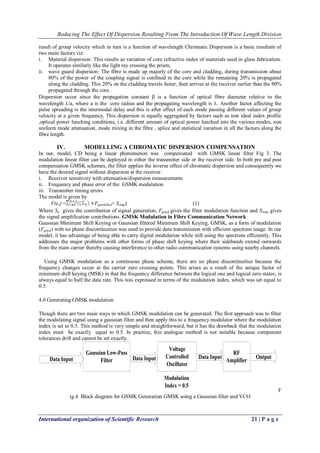
Fig 6 GSMK Modulator Fig 6 uses the gaussian frequency shaping filter. In the model, the GMSK is a Continuous Phase Modulation (CPM) signal with modulation index h =0.5 which is defined by the continuous phase shift function (t) and has the following complex baseband representation (t) = A exp Where T is bit period, A is amplitude, Xn = is the sequence of binary alphabet symbols,0 is random initial phase and (t) is the phase shift function. Constant envelop, continous-phase modulation schemes are robust against signal fading as well as interference and have good spectral efficiency. The slower and smoother the phase changes, the better the spectral efficiency. The schematic diagram of a GMSK modulator is shown in Fig.7 where GSMK signal is generated by modulating and adding two quadrature carriers with the frequency fc. phase changes are smoothed by a filter having gaussian impulse response [68].
g(t)=-Q (4) Where Q(t) is the Q-function given by
Q(t)=exp ()dr (9 and the phase shift function Q(t) in (4) is given by The key parameter in controlling both bandwidth and interference resistance is the 3-dB down filter bandwidth X bit interval product (BT) referred to as normalized bandwidth. The fibre GSMK uses BT = 0.3, which corresponds to spreading the effect of 1bit over approximately 3bits intervals. The channel separation or bandwidth at the TDMA burst rate of 271kbits/s (T =3.69s) is assumed to be BW = 200 kHz. The modulated spectrum must be 140 pulse length symbol intervals at both adjacent carrier frequencies.
(3)](https://image.slidesharecdn.com/c041021924-141106003343-conversion-gate01/85/C041021924-5-320.jpg)
![Reducing The Effect Of Dispersion Resulting From The Introduction Of Wave Length Division
International organization of Scientific Research 24 | P a g e
Base Station Bernoulli
Binary generator
Input bit Stream
0100101001
GMSK Modulator
Baseband
G
G
DAC
DAC
Amp
Amp
Modulator
Mapper
Pulse
Shaper
Symbols
Linear Filter
Compensator
Fiber Channel
Eye Diagram Sink
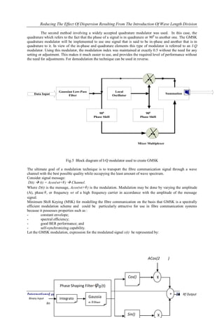
Fig. 7 System Model of the Fibre Communication Interface System
From Fig.7, the model started with the SMS binary source (Bernoulli block) into the transmission block
which comprises the convolutional encoding, data framing, interleaving, data burst and CRC. The block also has
the differential encoder and the GMSK modulation. afterwards, the channel block was implemented with the
addition white guassian noise (AWGN) at the receiver demodulation block which is comprise of the decoder
with the separation matched filter, mapping, CRC, decoder, the demodulation GMSK, differential decoder and
the reshape optimizer. The model ends the receiver interface with a gain amplifier and its sink. However, most
these blocks were not represented.
V. CONCLUSION AND RECOMMENDATION
From the analysis, it is clear that the GMSK modulation in optical fibre communication can conveniently
control dispersion of wave transmission. It is recommended that optical sensors be integrated into the GMSK
modulation for ease of monitoring.
REFERENCES
[1] Carmina, R.C and Paloma, R.H; Escuela Politecnica Superior, Universidad San Pablo CEU, ETSIT,
Universidad Politecnica de Madrid.
[2] Gerl Keiser, Optical Fibre Communications 3RD edition, Mcgraw-Hill International editions 2000.
[3] Gildas Chauvel, “Dispersion in Optical Fibres”, Anritsu paper, 2010.
[4] John, O’ Carrol, Ph.D thesis Faculty of Engineering and Cmputing, School of Electronic Engineering,
Jan. 2013.](https://image.slidesharecdn.com/c041021924-141106003343-conversion-gate01/85/C041021924-6-320.jpg)


![Available online at [www.ijeete.com]EFFECT OF DISPERSION AND FIBER LENGTH ON ...](https://cdn.slidesharecdn.com/ss_thumbnails/ij-v02-1516-e171-160112094437-thumbnail.jpg?width=640&height=640&fit=bounds)


![Getting Started with Apache Spark: Big Data Made Simple [Free Meetup]](https://cdn.slidesharecdn.com/ss_thumbnails/apachesparkgettingstarted-260203175547-8361bcc3-thumbnail.jpg?width=640&height=640&fit=bounds)
