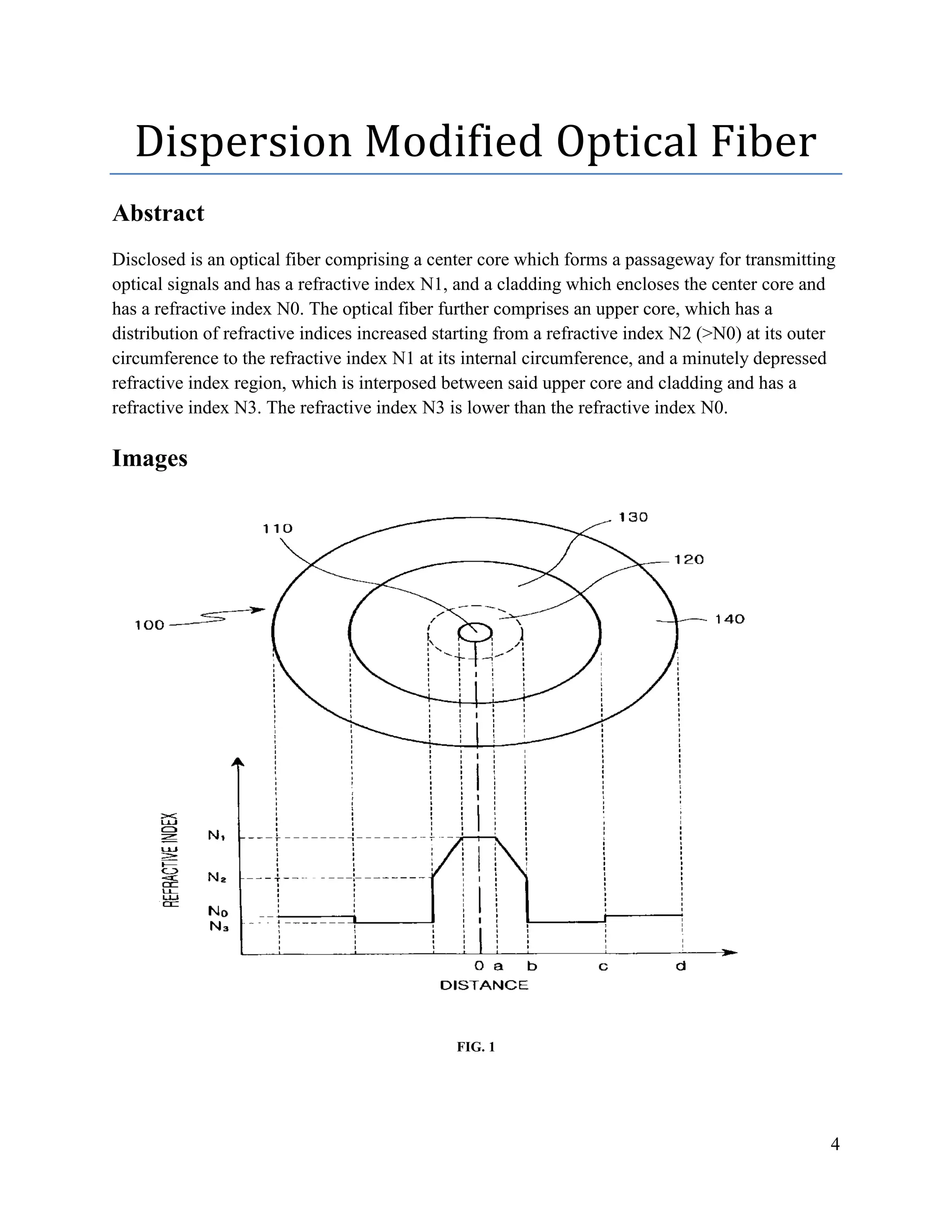
SlideShare a Scribd company logo
1
National University of Modern Languages
Assignment # 02
Name: Hassaan Ashraf
Roll # 11050
BEEE 7th
Semester
Optical Fiber Communication
Date: 30/11/2019
Submitted to:
Dr. Rizwan
2
Table of Content
Abstract ………………………………………………………………………….....4
Images ……………………………………………………………………………...4
Description ………………………………………………………………………....5
Summary of the Invention ………………………………………………………….6
Brief Description of Drawing ………………………………………………………7
Detail Description of the Preferred Embodiments …………………………………7
3
List of Figures
FIG. 1.............................................................................................................................................. 4
FIG. 2.............................................................................................................................................. 5
FIG. 3.............................................................................................................................................. 5
4
Dispersion Modified Optical Fiber
Abstract
Disclosed is an optical fiber comprising a center core which forms a passageway for transmitting
optical signals and has a refractive index N1, and a cladding which encloses the center core and
has a refractive index N0. The optical fiber further comprises an upper core, which has a
distribution of refractive indices increased starting from a refractive index N2 (>N0) at its outer
circumference to the refractive index N1 at its internal circumference, and a minutely depressed
refractive index region, which is interposed between said upper core and cladding and has a
refractive index N3. The refractive index N3 is lower than the refractive index N0.
Images
FIG. 1
5
FIG. 2
FIG. 3
6
Description
As one skilled in the art can readily appreciate, an optical fiber consists of a core and a cladding,
wherein the refractive index of the core is higher than that of the cladding. Common known
methods for manufacturing the base material of an optical fiber includes the Modified-Chemical-
Vapor Deposition (MCVD) method, Vapor-phase Axial Deposition (VAD) method, Outside
Vapor-phase Deposition(OVD) method, Plasma-Chemical-Vapor Deposition(PCVD) method
and the like.
For achieving ultra-high speed and high capacity communication, dispersion-controlled optical
fibers (for example, dispersion-shifted fiber (DSF), non-zero DSF (NZDSF), dispersion-
compensated fiber (DSF)) have been deployed which are superior to the existing single-mode
optical fiber in terms of transmission capability. As such, the demand for the dispersion-
controlled fibers has been increasing. If a region with a depressed refractive index is interposed
between the core and cladding to form an optical fiber, it is possible to effectively control the
dispersion characteristics of the optical fiber. An example of such an optical fiber is disclosed in
U.S. Pat. No. 4,715,679 to Venkata A. Bhagavatula, entitled “Low Dispersion, Low-loss Single-
mode Optical Waveguide.”
However, the dispersion-controlled optical fiber of this type has drawbacks in that its bending
loss tends to be high as it has a region with a highly depressed refractive index in its cladding. In
addition, a non-linear effect occurs due to its small effective cross-sectional area as it has a small
mode-field diameter (MFD) when compared to common single-mode optical fibers.
Furthermore, it is inappropriate for broad-band transmission, and the loss and dispersion
characteristics are poor in higher and lower wavelength ranges. A dispersion-controlled optical
fiber has a very small core diameter and high refractive index when compared to a single-mode
optical fiber. As such, if the dimension of its base material forms a large aperture, a problem will
arise as relatively large stresses are applied to the core part at the time of drawing it. Namely, the
distribution of wavelengths will be changed. This means that it is difficult for various optical
characteristics to have constant values in accordance with drawing temperatures. Also, it is not
easy to manufacture a dispersion-controlled optical fiber if it has relatively sensitive
characteristics when compared to a common single-mode optical fiber. In addition, the existing
dispersion-controlled optical fibers are adapted to be used in the wavelength range of about
1530˜1565 nm by setting the zero dispersion wavelength around 1530 nm, wherein the optical
fibers have a dispersion characteristic of not more than 5 ps/nm·km at 1550 nm and their
diameters range between 8˜9 μm, thus being problematic in that they are inappropriate for
communication exceeding the 10 Gbps level.
7
As explained above, dispersion-controlled optical fibers in the prior art have the following
problems:
 a) the existing dispersion-controlled optical fibers, such as a dispersion-compensated
fiber, dispersion-shifted fiber, non-zero dispersion-shifted fiber, use a small wavelength
window as the zero dispersion is positioned adjacent to 1530 nm, thus not suitable for use
in high capacity transmission;
 b) an optical fiber of low dispersion has the problem of exhibiting a small dispersion
characteristic, i.e., a non-linear effect (four-wave mixing (FWM), and a cross-phase
modulation (XPM)) is generated at the time of super-high speed transmission;
 c) a common single-mode optical fiber has the problem of exhibiting an overly large
dispersion (≧17 ps/nm·km) characteristic in the EDF window, thus a non-linear effect
(self phase modulation (SPM)) is produced; and,
 d) if an optical fiber has a high core-refractive index and a small core diameter in order to
control the dispersion characteristic, a problem may arise in that it may be greatly
influenced by a non-linear effect as it has a small mode-field diameter (effective cross-
sectional area at 1550 nm<50 μm2
). In addition, there is a problem in that the
aforementioned non-linear effect is further amplified if the dispersion value is either too
large or too small (XPM, SPM and FWM have a trade-off relationship), thereby
deteriorating transmission characteristics.
Summary of the Invention
Accordingly, the present invention has been made to solve the above-mentioned problems
occurring in the prior art and provides a dispersion-controlled optical fiber, in which a desired
dispersion characteristic and a dispersion slope characteristic can be obtained, and further has a
low-loss characteristic.
Another aspect of the present invention is to provide a dispersion-controlled optical fiber, in
which a large effective cross-sectional area can be obtained to reduce a non-linear effect with a
large mode-field diameter through a large core diameter.
Another aspect of the present invention is to provide a dispersion-controlled optical fiber, which
can secure a broad range of usable wavelengths (1400˜1625 nm) by positioning a zero-dispersion
wavelength range on or below 1400 nm, and which can have a dispersion characteristic in the
range of about 5˜13 ps/nm·km at 1550 nm, thus reducing the non-linear effect.
Accordingly, there is provided an optical fiber comprising a center core which forms a
passageway for transmitting optical signals and has a refractive index N1, and a cladding that
encloses the center core and has a refractive index N0, wherein the optical fiber further comprises
an upper core that has a distribution of refractive indices, which increase starting from a
refractive index N2 (>N0) at its outer circumference to the refractive index N1 at its internal
circumference, and a minutely-depressed, refractive-index region, which is interposed between
8
the upper core and the cladding and has a refractive index N3, wherein the refractive index N3 is
lower than the refractive index N0.
Brief Description of Drawing
The above and other features and advantages of the present invention will be more apparent from
the following detailed description taken in conjunction with the accompanying drawings, in
which:
 FIG. 1 shows the construction and distribution of refractive indices of a dispersion-
controlled optical fiber according to a preferred embodiment of the present invention;
 FIG. 2 shows the dispersion characteristic of the dispersion-controlled optical fiber
shown in FIG. 1; and,
 FIG. 3 shows the loss characteristic of the dispersion-controlled optical fiber shown in
FIG. 1.
Detail Description of the Preferred Embodiments
Hereinafter, preferred embodiments of the present invention will be described in detail with
reference to the accompanying drawings. For the purposes of clarity and simplicity, a detailed
description of known functions and configurations incorporated herein will be omitted as it may
make the subject matter of the present invention unclear.
FIG. 1 shows the construction and distribution of the refractive indices of a dispersion-controlled
optical fiber in accordance with a preferred embodiment of the present invention. As shown in
FIG. 1, the dispersion-controlled optical fiber 100 consists of a center core 110, an upper core
120, a minutely depressed refractive index region 130, and a cladding 140.The center core 110
consists of silica and has a radius, a. In the embodiment, the center core 110 is doped with a
predetermined amount of germanium for tuning its refractive index to N1.The upper core 120 has
an internal radius of a and an external radius of b, and a refractive index of N1 at its internal
circumference and a refractive index of N2 at its external circumference. As shown in FIG. 1, the
refractive indices of the upper core 120 linearly increases from the external circumstance to the
internal circumstance.The minutely-depressed, refractive-index region 130 is formed from a
silica material with an internal radius of b and an external radius of c. Furthermore, the minutely
depressed refractive index region 130 is doped with germanium, phosphorus, and fluorine in a
predetermined ratio for tuning its refractive index to N3.The cladding 140 is formed of silica and
has an internal radius of a and an external radius of b, and further has a refractive index of N0,
which is higher than N3 and lower than N2.As constructed above, the zero-dispersion
characteristic exists in the dispersion-controlled optical fiber 100 at the region of wavelengths
below 1400 nm, and the dispersion-controlled optical fiber 100 has a predetermined range of
dispersion values (0.1˜4 ps/nm·km at 1400 nm, 5˜13 ps/nm·km at 1550 nm, and 8˜16 ps/nm·km
at 1625 nm) and a large MFD or effective cross-sectional area (8.5˜10.0 μm at 1550 nm), thereby
reducing the non-linear effect. For this purpose, the dispersion-controlled optical fiber 100
conforms to the relationships of 0.06≦a/c≦0.9, 0.06≦a/b≦0.8, 0.02≦a/c≦0.9, 1.2≦N1/N2≦2.67
9
and −8≦N1/N3≦1.6. In this case, the refractive index of referenced glass exhibits 1.45709 when
measured with a He—Ne laser at 632.8 nm.
FIG. 2 shows the dispersion characteristic of dispersion-controlled optical fiber 100 shown in
FIG. 1, and FIG. 3 shows the loss characteristic of dispersion-controlled optical fiber 100 shown
in FIG. 1. FIGS. 2 and 3 show the case where a/b=0.206, a/c=0.0781, N1=0.4781%, N2=0.273%,
and N3=−0.0683%, in which the dispersion values at 1400˜1625 are 2˜16 ps/nm·km and the
mode field diameter at 1550 nm is 9.5 μm. In this case, the refractive index of referenced glass
exhibits 1.45709 when measured with a He—Ne laser at 632.8 nm, wherein N1, N2, N3 indicate
the percentage of this value, and a=0.5, b=2.43, and c=6.4.The upper core 120, which has the
predetermined refractive index slope, permits a large mode field diameter and can be tuned to
have the desired dispersion value and dispersion-slope characteristics, together with the
minutely-depressed, refractive-index region 130. As the minutely-depressed, refractive-index
region 130 has a refractive index that is minutely different from that of the cladding 140, a
minute bending may be induced which is small when compared to the prior art, thereby reducing
the bending loss.In the optical characteristics, if the dispersion is too high, the transmission
length of the optical fiber will be restricted and the transmission characteristics will be
deteriorated by a self-phase modulation due to phase shifting caused by the non-linear effect. In
addition, the dispersion value at a wavelength near zero-dispersion and the small dispersion-
value characteristic readily cause phase matching, whereby the transmission characteristic will
be deteriorated by four-wave mixing process in the case of multiple-channel transmission, which
is typically employed to extend the transmission capacity. Accordingly, it is necessary to have a
proper dispersion value to allow a super-high speed and broad-band transmission and to have a
large mode-field diameter in order to reduce the non-linear effect. As such, the dispersion-
controlled optical fiber in accordance with the present invention can obtain a dispersion value
and dispersion slope suitable for super-high speed and broad-band transmission through the
tuning of the minutely-depressed, refractive-index region and upper core. Furthermore, the
dispersion-controlled optical fiber in accordance with the present invention has a loss not
exceeding 0.25 dB/km, a cutoff wavelength not exceeding 1400 nm, and a dispersion slope not
exceeding 0.08 ps/nm2
·km, at the wavelength of 1550 nm, has a dispersion value not less than
0.1 ps/nm·km at the wavelength of 1400 nm and a dispersion value not exceeding 16 ps/nm·km
at the wavelength of 1625 nm, and further has a mode-field diameter not less than 8.2 μm at the
wavelength of 1550 nm, thus it has suitable optical characteristics for wavelength-division
multiplexing transmission using a wavelength band of 1400˜1625 nm.
In summary, as explained above, the dispersion-controlled optical fiber has the following
advantages:
 it has a large effective cross-sectional area, whereby it can reduce the non-linear effect;
 b) it can easily provide a dispersion value and a dispersion slope that are suitable for
super-high speed and broad band-transmission through the tuning of the minutely
depressed refractive index region and upper core; and,
 c) due to the fine difference in refractive indices between the minutely depressed
refractive index region and upper core, the bending loss can be reduced.
10
While the invention has been shown and described with reference to certain preferred
embodiments thereof, it will be understood by those skilled in the art that various changes in
form and details may be made therein without departing from the spirit and scope of the
invention as defined by the appended claims.
11
Reference
[1]
L. G. Cohen et al., “Tailoring zero chromatic dispersion into the 1.5 μm-1.6 μm low-loss
spectral region of single-mode fibres”, Electron. Lett. 15 (12), 334 (1979)
[2] M. A. Saifi et al., “Triangular-profile single-mode fiber”, Opt. Lett. 7 (1), 43 (1982)
[3]
B. J. Ainslie et al., “Monomode fibre with ultra-low loss and minimum dispersion at
1.55 μm”, Electron. Lett. 18, 842 (1982)
[4]
V. A. Bhagavatula and M. S. Spitz, “Dispersion-shifted segmented-core single-mode fibers”,
Opt. Lett. 9 (5), 186 (1984)

More Related Content

What's hot

Non linear effects in optical fibers
Non linear effects in optical fibersNon linear effects in optical fibers
Non linear effects in optical fibers
CKSunith1
 
Laser diode structures
Laser diode structuresLaser diode structures
Laser diode structures
CKSunith1
 
Optical fiber Communication
Optical fiber CommunicationOptical fiber Communication
Optical fiber Communication
Amogha Bandrikalli
 
Optical fiber communiction system
Optical fiber communiction systemOptical fiber communiction system
Optical fiber communiction systemrahulohlan14
 
Modulation of LED
Modulation of LEDModulation of LED
Modulation of LED
Priyanka Anni
 
Unit 3- OPTICAL SOURCES AND DETECTORS
Unit 3- OPTICAL SOURCES AND DETECTORS Unit 3- OPTICAL SOURCES AND DETECTORS
Unit 3- OPTICAL SOURCES AND DETECTORS
tamil arasan
 
optical fiber communication system
optical fiber communication systemoptical fiber communication system
optical fiber communication system
Muhammad Ahsan
 
Losses in fibers
Losses in fibersLosses in fibers
Losses in fibers
DEPARTMENT OF PHYSICS
 
Optical fiber communication
Optical fiber          communicationOptical fiber          communication
Optical fiber communication
anitha bolleddu
 
Fiber optic communications
Fiber optic communicationsFiber optic communications
Fiber optic communications
Dr.YNM
 
Optical fiber communication-Presented by Kiran Devkota
Optical fiber communication-Presented by Kiran DevkotaOptical fiber communication-Presented by Kiran Devkota
Optical fiber communication-Presented by Kiran Devkota
Sujit Jha
 
Dispersion in optical fibers
Dispersion in optical fibersDispersion in optical fibers
Dispersion in optical fibers
CKSunith1
 
Vapor Phase Deposition Techniques
Vapor Phase Deposition TechniquesVapor Phase Deposition Techniques
Vapor Phase Deposition Techniques
Sowren Sen
 
optical-fiber-communication
optical-fiber-communicationoptical-fiber-communication
optical-fiber-communication
ATTO RATHORE
 
Optical communications
Optical communicationsOptical communications
Optical communications
krishslide
 
Fibre optics
Fibre opticsFibre optics
Fibre optics
Saurabh Rana
 
WDM Networks
WDM NetworksWDM Networks
WDM Networks
CKSunith1
 
Measurement of optical fiber length
Measurement of optical fiber lengthMeasurement of optical fiber length
Measurement of optical fiber length
CKSunith1
 
Optical Fiber
Optical FiberOptical Fiber
Optical Fiber
TharunSangeeth
 
Optical fiber (Fiber Optics)
Optical fiber (Fiber Optics)Optical fiber (Fiber Optics)
Optical fiber (Fiber Optics)
Abdessalam Benharira
 

What's hot (20)

Non linear effects in optical fibers
Non linear effects in optical fibersNon linear effects in optical fibers
Non linear effects in optical fibers
 
Laser diode structures
Laser diode structuresLaser diode structures
Laser diode structures
 
Optical fiber Communication
Optical fiber CommunicationOptical fiber Communication
Optical fiber Communication
 
Optical fiber communiction system
Optical fiber communiction systemOptical fiber communiction system
Optical fiber communiction system
 
Modulation of LED
Modulation of LEDModulation of LED
Modulation of LED
 
Unit 3- OPTICAL SOURCES AND DETECTORS
Unit 3- OPTICAL SOURCES AND DETECTORS Unit 3- OPTICAL SOURCES AND DETECTORS
Unit 3- OPTICAL SOURCES AND DETECTORS
 
optical fiber communication system
optical fiber communication systemoptical fiber communication system
optical fiber communication system
 
Losses in fibers
Losses in fibersLosses in fibers
Losses in fibers
 
Optical fiber communication
Optical fiber          communicationOptical fiber          communication
Optical fiber communication
 
Fiber optic communications
Fiber optic communicationsFiber optic communications
Fiber optic communications
 
Optical fiber communication-Presented by Kiran Devkota
Optical fiber communication-Presented by Kiran DevkotaOptical fiber communication-Presented by Kiran Devkota
Optical fiber communication-Presented by Kiran Devkota
 
Dispersion in optical fibers
Dispersion in optical fibersDispersion in optical fibers
Dispersion in optical fibers
 
Vapor Phase Deposition Techniques
Vapor Phase Deposition TechniquesVapor Phase Deposition Techniques
Vapor Phase Deposition Techniques
 
optical-fiber-communication
optical-fiber-communicationoptical-fiber-communication
optical-fiber-communication
 
Optical communications
Optical communicationsOptical communications
Optical communications
 
Fibre optics
Fibre opticsFibre optics
Fibre optics
 
WDM Networks
WDM NetworksWDM Networks
WDM Networks
 
Measurement of optical fiber length
Measurement of optical fiber lengthMeasurement of optical fiber length
Measurement of optical fiber length
 
Optical Fiber
Optical FiberOptical Fiber
Optical Fiber
 
Optical fiber (Fiber Optics)
Optical fiber (Fiber Optics)Optical fiber (Fiber Optics)
Optical fiber (Fiber Optics)
 

Similar to Dispersion Modified Optical Fiber

Oc unit 2 - Part II - Transmission Characteristics
Oc   unit 2 - Part II - Transmission CharacteristicsOc   unit 2 - Part II - Transmission Characteristics
Oc unit 2 - Part II - Transmission Characteristics
KannanKrishnana
 
Effects of structural parameters of photonic crystal fiber
Effects of structural parameters of photonic crystal fiberEffects of structural parameters of photonic crystal fiber
Effects of structural parameters of photonic crystal fiber
Saswati Rudra Paul
 
What is pcf
What is  pcfWhat is  pcf
What is pcf
Rahul Dutta
 
Module of fiber coupled diode laser based on 808nm single emitter combination
Module of fiber coupled diode laser based on 808nm single emitter combinationModule of fiber coupled diode laser based on 808nm single emitter combination
Module of fiber coupled diode laser based on 808nm single emitter combination
Naku Technology Co,. Ltd
 
photonic crystal fibers -The nonlinear scattering effects in optical fibers a...
photonic crystal fibers -The nonlinear scattering effects in optical fibers a...photonic crystal fibers -The nonlinear scattering effects in optical fibers a...
photonic crystal fibers -The nonlinear scattering effects in optical fibers a...
VasuhiSamydurai1
 
Twenty Essential Knowledge of Optical Cable.pdf
Twenty Essential Knowledge of Optical Cable.pdfTwenty Essential Knowledge of Optical Cable.pdf
Twenty Essential Knowledge of Optical Cable.pdf
HYC Co., Ltd
 
Photonic crystal fibers
Photonic crystal fibersPhotonic crystal fibers
Photonic crystal fibers
ajay singh
 
Diffractive Optics Manufacturing
Diffractive Optics ManufacturingDiffractive Optics Manufacturing
Diffractive Optics Manufacturing
AlexCarter68
 
Optical fibres by Dr Praful D Shirbhate
Optical fibres by Dr Praful D ShirbhateOptical fibres by Dr Praful D Shirbhate
Optical fibres by Dr Praful D Shirbhate
Dr Praful D Shirbhate
 
Photonic Crystal as Dispersion Compensating Element.pptx
Photonic Crystal as Dispersion Compensating Element.pptxPhotonic Crystal as Dispersion Compensating Element.pptx
Photonic Crystal as Dispersion Compensating Element.pptx
AdityaNarayanSingh18
 
Fiber optics 1-3
Fiber optics 1-3Fiber optics 1-3
Fiber optics 1-3
grantlerc
 
Retro-Reflective_Fiber_Optic_Displacement_Sensor.pptx
Retro-Reflective_Fiber_Optic_Displacement_Sensor.pptxRetro-Reflective_Fiber_Optic_Displacement_Sensor.pptx
Retro-Reflective_Fiber_Optic_Displacement_Sensor.pptx
pooja82042
 
Fiber Optics Course
Fiber Optics Course Fiber Optics Course
Fiber Optics Course
Ahmed OM
 
Ep notes
Ep notesEp notes
Ep notes
Abhi Hirpara
 
EFFECT OF TOD AND GVD IN LONG-HAUL OFC SYSTEM
EFFECT OF TOD AND GVD IN LONG-HAUL OFC SYSTEMEFFECT OF TOD AND GVD IN LONG-HAUL OFC SYSTEM
EFFECT OF TOD AND GVD IN LONG-HAUL OFC SYSTEM
International Journal of Technical Research & Application
 
Characteristics of optical fiber cable
Characteristics of optical fiber cableCharacteristics of optical fiber cable
Characteristics of optical fiber cable
Bala V
 
Optical Comm-Attenuation and dispersion in fiber.pdf
Optical Comm-Attenuation and dispersion in fiber.pdfOptical Comm-Attenuation and dispersion in fiber.pdf
Optical Comm-Attenuation and dispersion in fiber.pdf
Rajarao Manda
 
Effects of Parameters of Photonic Crystal Fibre on Dispersion and Confinement
Effects of Parameters of Photonic Crystal Fibre on Dispersion and ConfinementEffects of Parameters of Photonic Crystal Fibre on Dispersion and Confinement
Effects of Parameters of Photonic Crystal Fibre on Dispersion and Confinement
IJAEMSJORNAL
 

Similar to Dispersion Modified Optical Fiber (20)

Oc unit 2 - Part II - Transmission Characteristics
Oc   unit 2 - Part II - Transmission CharacteristicsOc   unit 2 - Part II - Transmission Characteristics
Oc unit 2 - Part II - Transmission Characteristics
 
Effects of structural parameters of photonic crystal fiber
Effects of structural parameters of photonic crystal fiberEffects of structural parameters of photonic crystal fiber
Effects of structural parameters of photonic crystal fiber
 
What is pcf
What is  pcfWhat is  pcf
What is pcf
 
Lec10.pdf
Lec10.pdfLec10.pdf
Lec10.pdf
 
Module of fiber coupled diode laser based on 808nm single emitter combination
Module of fiber coupled diode laser based on 808nm single emitter combinationModule of fiber coupled diode laser based on 808nm single emitter combination
Module of fiber coupled diode laser based on 808nm single emitter combination
 
photonic crystal fibers -The nonlinear scattering effects in optical fibers a...
photonic crystal fibers -The nonlinear scattering effects in optical fibers a...photonic crystal fibers -The nonlinear scattering effects in optical fibers a...
photonic crystal fibers -The nonlinear scattering effects in optical fibers a...
 
Twenty Essential Knowledge of Optical Cable.pdf
Twenty Essential Knowledge of Optical Cable.pdfTwenty Essential Knowledge of Optical Cable.pdf
Twenty Essential Knowledge of Optical Cable.pdf
 
Photonic crystal fibers
Photonic crystal fibersPhotonic crystal fibers
Photonic crystal fibers
 
Diffractive Optics Manufacturing
Diffractive Optics ManufacturingDiffractive Optics Manufacturing
Diffractive Optics Manufacturing
 
Optical fibres by Dr Praful D Shirbhate
Optical fibres by Dr Praful D ShirbhateOptical fibres by Dr Praful D Shirbhate
Optical fibres by Dr Praful D Shirbhate
 
PhC_presentation
PhC_presentationPhC_presentation
PhC_presentation
 
Photonic Crystal as Dispersion Compensating Element.pptx
Photonic Crystal as Dispersion Compensating Element.pptxPhotonic Crystal as Dispersion Compensating Element.pptx
Photonic Crystal as Dispersion Compensating Element.pptx
 
Fiber optics 1-3
Fiber optics 1-3Fiber optics 1-3
Fiber optics 1-3
 
Retro-Reflective_Fiber_Optic_Displacement_Sensor.pptx
Retro-Reflective_Fiber_Optic_Displacement_Sensor.pptxRetro-Reflective_Fiber_Optic_Displacement_Sensor.pptx
Retro-Reflective_Fiber_Optic_Displacement_Sensor.pptx
 
Fiber Optics Course
Fiber Optics Course Fiber Optics Course
Fiber Optics Course
 
Ep notes
Ep notesEp notes
Ep notes
 
EFFECT OF TOD AND GVD IN LONG-HAUL OFC SYSTEM
EFFECT OF TOD AND GVD IN LONG-HAUL OFC SYSTEMEFFECT OF TOD AND GVD IN LONG-HAUL OFC SYSTEM
EFFECT OF TOD AND GVD IN LONG-HAUL OFC SYSTEM
 
Characteristics of optical fiber cable
Characteristics of optical fiber cableCharacteristics of optical fiber cable
Characteristics of optical fiber cable
 
Optical Comm-Attenuation and dispersion in fiber.pdf
Optical Comm-Attenuation and dispersion in fiber.pdfOptical Comm-Attenuation and dispersion in fiber.pdf
Optical Comm-Attenuation and dispersion in fiber.pdf
 
Effects of Parameters of Photonic Crystal Fibre on Dispersion and Confinement
Effects of Parameters of Photonic Crystal Fibre on Dispersion and ConfinementEffects of Parameters of Photonic Crystal Fibre on Dispersion and Confinement
Effects of Parameters of Photonic Crystal Fibre on Dispersion and Confinement
 

Recently uploaded

Nuclear Power Economics and Structuring 2024
Nuclear Power Economics and Structuring 2024Nuclear Power Economics and Structuring 2024
Nuclear Power Economics and Structuring 2024
Massimo Talia
 
Industrial Training at Shahjalal Fertilizer Company Limited (SFCL)
Industrial Training at Shahjalal Fertilizer Company Limited (SFCL)Industrial Training at Shahjalal Fertilizer Company Limited (SFCL)
Industrial Training at Shahjalal Fertilizer Company Limited (SFCL)
MdTanvirMahtab2
 
TECHNICAL TRAINING MANUAL GENERAL FAMILIARIZATION COURSE
TECHNICAL TRAINING MANUAL   GENERAL FAMILIARIZATION COURSETECHNICAL TRAINING MANUAL   GENERAL FAMILIARIZATION COURSE
TECHNICAL TRAINING MANUAL GENERAL FAMILIARIZATION COURSE
DuvanRamosGarzon1
 
weather web application report.pdf
weather web application report.pdfweather web application report.pdf
weather web application report.pdf
Pratik Pawar
 
Vaccine management system project report documentation..pdf
Vaccine management system project report documentation..pdfVaccine management system project report documentation..pdf
Vaccine management system project report documentation..pdf
Kamal Acharya
 
Immunizing Image Classifiers Against Localized Adversary Attacks
Immunizing Image Classifiers Against Localized Adversary AttacksImmunizing Image Classifiers Against Localized Adversary Attacks
Immunizing Image Classifiers Against Localized Adversary Attacks
gerogepatton
 
Architectural Portfolio Sean Lockwood
Architectural Portfolio Sean LockwoodArchitectural Portfolio Sean Lockwood
Architectural Portfolio Sean Lockwood
seandesed
 
COLLEGE BUS MANAGEMENT SYSTEM PROJECT REPORT.pdf
COLLEGE BUS MANAGEMENT SYSTEM PROJECT REPORT.pdfCOLLEGE BUS MANAGEMENT SYSTEM PROJECT REPORT.pdf
COLLEGE BUS MANAGEMENT SYSTEM PROJECT REPORT.pdf
Kamal Acharya
 
Pile Foundation by Venkatesh Taduvai (Sub Geotechnical Engineering II)-conver...
Pile Foundation by Venkatesh Taduvai (Sub Geotechnical Engineering II)-conver...Pile Foundation by Venkatesh Taduvai (Sub Geotechnical Engineering II)-conver...
Pile Foundation by Venkatesh Taduvai (Sub Geotechnical Engineering II)-conver...
AJAYKUMARPUND1
 
Student information management system project report ii.pdf
Student information management system project report ii.pdfStudent information management system project report ii.pdf
Student information management system project report ii.pdf
Kamal Acharya
 
road safety engineering r s e unit 3.pdf
road safety engineering  r s e unit 3.pdfroad safety engineering  r s e unit 3.pdf
road safety engineering r s e unit 3.pdf
VENKATESHvenky89705
 
H.Seo, ICLR 2024, MLILAB, KAIST AI.pdf
H.Seo,  ICLR 2024, MLILAB,  KAIST AI.pdfH.Seo,  ICLR 2024, MLILAB,  KAIST AI.pdf
H.Seo, ICLR 2024, MLILAB, KAIST AI.pdf
MLILAB
 
Gen AI Study Jams _ For the GDSC Leads in India.pdf
Gen AI Study Jams _ For the GDSC Leads in India.pdfGen AI Study Jams _ For the GDSC Leads in India.pdf
Gen AI Study Jams _ For the GDSC Leads in India.pdf
gdsczhcet
 
HYDROPOWER - Hydroelectric power generation
HYDROPOWER - Hydroelectric power generationHYDROPOWER - Hydroelectric power generation
HYDROPOWER - Hydroelectric power generation
Robbie Edward Sayers
 
block diagram and signal flow graph representation
block diagram and signal flow graph representationblock diagram and signal flow graph representation
block diagram and signal flow graph representation
Divya Somashekar
 
WATER CRISIS and its solutions-pptx 1234
WATER CRISIS and its solutions-pptx 1234WATER CRISIS and its solutions-pptx 1234
WATER CRISIS and its solutions-pptx 1234
AafreenAbuthahir2
 
Halogenation process of chemical process industries
Halogenation process of chemical process industriesHalogenation process of chemical process industries
Halogenation process of chemical process industries
MuhammadTufail242431
 
Automobile Management System Project Report.pdf
Automobile Management System Project Report.pdfAutomobile Management System Project Report.pdf
Automobile Management System Project Report.pdf
Kamal Acharya
 
Sachpazis:Terzaghi Bearing Capacity Estimation in simple terms with Calculati...
Sachpazis:Terzaghi Bearing Capacity Estimation in simple terms with Calculati...Sachpazis:Terzaghi Bearing Capacity Estimation in simple terms with Calculati...
Sachpazis:Terzaghi Bearing Capacity Estimation in simple terms with Calculati...
Dr.Costas Sachpazis
 
ethical hacking in wireless-hacking1.ppt
ethical hacking in wireless-hacking1.pptethical hacking in wireless-hacking1.ppt
ethical hacking in wireless-hacking1.ppt
Jayaprasanna4
 

Recently uploaded (20)

Nuclear Power Economics and Structuring 2024
Nuclear Power Economics and Structuring 2024Nuclear Power Economics and Structuring 2024
Nuclear Power Economics and Structuring 2024
 
Industrial Training at Shahjalal Fertilizer Company Limited (SFCL)
Industrial Training at Shahjalal Fertilizer Company Limited (SFCL)Industrial Training at Shahjalal Fertilizer Company Limited (SFCL)
Industrial Training at Shahjalal Fertilizer Company Limited (SFCL)
 
TECHNICAL TRAINING MANUAL GENERAL FAMILIARIZATION COURSE
TECHNICAL TRAINING MANUAL   GENERAL FAMILIARIZATION COURSETECHNICAL TRAINING MANUAL   GENERAL FAMILIARIZATION COURSE
TECHNICAL TRAINING MANUAL GENERAL FAMILIARIZATION COURSE
 
weather web application report.pdf
weather web application report.pdfweather web application report.pdf
weather web application report.pdf
 
Vaccine management system project report documentation..pdf
Vaccine management system project report documentation..pdfVaccine management system project report documentation..pdf
Vaccine management system project report documentation..pdf
 
Immunizing Image Classifiers Against Localized Adversary Attacks
Immunizing Image Classifiers Against Localized Adversary AttacksImmunizing Image Classifiers Against Localized Adversary Attacks
Immunizing Image Classifiers Against Localized Adversary Attacks
 
Architectural Portfolio Sean Lockwood
Architectural Portfolio Sean LockwoodArchitectural Portfolio Sean Lockwood
Architectural Portfolio Sean Lockwood
 
COLLEGE BUS MANAGEMENT SYSTEM PROJECT REPORT.pdf
COLLEGE BUS MANAGEMENT SYSTEM PROJECT REPORT.pdfCOLLEGE BUS MANAGEMENT SYSTEM PROJECT REPORT.pdf
COLLEGE BUS MANAGEMENT SYSTEM PROJECT REPORT.pdf
 
Pile Foundation by Venkatesh Taduvai (Sub Geotechnical Engineering II)-conver...
Pile Foundation by Venkatesh Taduvai (Sub Geotechnical Engineering II)-conver...Pile Foundation by Venkatesh Taduvai (Sub Geotechnical Engineering II)-conver...
Pile Foundation by Venkatesh Taduvai (Sub Geotechnical Engineering II)-conver...
 
Student information management system project report ii.pdf
Student information management system project report ii.pdfStudent information management system project report ii.pdf
Student information management system project report ii.pdf
 
road safety engineering r s e unit 3.pdf
road safety engineering  r s e unit 3.pdfroad safety engineering  r s e unit 3.pdf
road safety engineering r s e unit 3.pdf
 
H.Seo, ICLR 2024, MLILAB, KAIST AI.pdf
H.Seo,  ICLR 2024, MLILAB,  KAIST AI.pdfH.Seo,  ICLR 2024, MLILAB,  KAIST AI.pdf
H.Seo, ICLR 2024, MLILAB, KAIST AI.pdf
 
Gen AI Study Jams _ For the GDSC Leads in India.pdf
Gen AI Study Jams _ For the GDSC Leads in India.pdfGen AI Study Jams _ For the GDSC Leads in India.pdf
Gen AI Study Jams _ For the GDSC Leads in India.pdf
 
HYDROPOWER - Hydroelectric power generation
HYDROPOWER - Hydroelectric power generationHYDROPOWER - Hydroelectric power generation
HYDROPOWER - Hydroelectric power generation
 
block diagram and signal flow graph representation
block diagram and signal flow graph representationblock diagram and signal flow graph representation
block diagram and signal flow graph representation
 
WATER CRISIS and its solutions-pptx 1234
WATER CRISIS and its solutions-pptx 1234WATER CRISIS and its solutions-pptx 1234
WATER CRISIS and its solutions-pptx 1234
 
Halogenation process of chemical process industries
Halogenation process of chemical process industriesHalogenation process of chemical process industries
Halogenation process of chemical process industries
 
Automobile Management System Project Report.pdf
Automobile Management System Project Report.pdfAutomobile Management System Project Report.pdf
Automobile Management System Project Report.pdf
 
Sachpazis:Terzaghi Bearing Capacity Estimation in simple terms with Calculati...
Sachpazis:Terzaghi Bearing Capacity Estimation in simple terms with Calculati...Sachpazis:Terzaghi Bearing Capacity Estimation in simple terms with Calculati...
Sachpazis:Terzaghi Bearing Capacity Estimation in simple terms with Calculati...
 
ethical hacking in wireless-hacking1.ppt
ethical hacking in wireless-hacking1.pptethical hacking in wireless-hacking1.ppt
ethical hacking in wireless-hacking1.ppt
 

Dispersion Modified Optical Fiber

  • 1. 1 National University of Modern Languages Assignment # 02 Name: Hassaan Ashraf Roll # 11050 BEEE 7th Semester Optical Fiber Communication Date: 30/11/2019 Submitted to: Dr. Rizwan
  • 2. 2 Table of Content Abstract ………………………………………………………………………….....4 Images ……………………………………………………………………………...4 Description ………………………………………………………………………....5 Summary of the Invention ………………………………………………………….6 Brief Description of Drawing ………………………………………………………7 Detail Description of the Preferred Embodiments …………………………………7
  • 3. 3 List of Figures FIG. 1.............................................................................................................................................. 4 FIG. 2.............................................................................................................................................. 5 FIG. 3.............................................................................................................................................. 5
  • 4. 4 Dispersion Modified Optical Fiber Abstract Disclosed is an optical fiber comprising a center core which forms a passageway for transmitting optical signals and has a refractive index N1, and a cladding which encloses the center core and has a refractive index N0. The optical fiber further comprises an upper core, which has a distribution of refractive indices increased starting from a refractive index N2 (>N0) at its outer circumference to the refractive index N1 at its internal circumference, and a minutely depressed refractive index region, which is interposed between said upper core and cladding and has a refractive index N3. The refractive index N3 is lower than the refractive index N0. Images FIG. 1
  • 6. 6 Description As one skilled in the art can readily appreciate, an optical fiber consists of a core and a cladding, wherein the refractive index of the core is higher than that of the cladding. Common known methods for manufacturing the base material of an optical fiber includes the Modified-Chemical- Vapor Deposition (MCVD) method, Vapor-phase Axial Deposition (VAD) method, Outside Vapor-phase Deposition(OVD) method, Plasma-Chemical-Vapor Deposition(PCVD) method and the like. For achieving ultra-high speed and high capacity communication, dispersion-controlled optical fibers (for example, dispersion-shifted fiber (DSF), non-zero DSF (NZDSF), dispersion- compensated fiber (DSF)) have been deployed which are superior to the existing single-mode optical fiber in terms of transmission capability. As such, the demand for the dispersion- controlled fibers has been increasing. If a region with a depressed refractive index is interposed between the core and cladding to form an optical fiber, it is possible to effectively control the dispersion characteristics of the optical fiber. An example of such an optical fiber is disclosed in U.S. Pat. No. 4,715,679 to Venkata A. Bhagavatula, entitled “Low Dispersion, Low-loss Single- mode Optical Waveguide.” However, the dispersion-controlled optical fiber of this type has drawbacks in that its bending loss tends to be high as it has a region with a highly depressed refractive index in its cladding. In addition, a non-linear effect occurs due to its small effective cross-sectional area as it has a small mode-field diameter (MFD) when compared to common single-mode optical fibers. Furthermore, it is inappropriate for broad-band transmission, and the loss and dispersion characteristics are poor in higher and lower wavelength ranges. A dispersion-controlled optical fiber has a very small core diameter and high refractive index when compared to a single-mode optical fiber. As such, if the dimension of its base material forms a large aperture, a problem will arise as relatively large stresses are applied to the core part at the time of drawing it. Namely, the distribution of wavelengths will be changed. This means that it is difficult for various optical characteristics to have constant values in accordance with drawing temperatures. Also, it is not easy to manufacture a dispersion-controlled optical fiber if it has relatively sensitive characteristics when compared to a common single-mode optical fiber. In addition, the existing dispersion-controlled optical fibers are adapted to be used in the wavelength range of about 1530˜1565 nm by setting the zero dispersion wavelength around 1530 nm, wherein the optical fibers have a dispersion characteristic of not more than 5 ps/nm·km at 1550 nm and their diameters range between 8˜9 μm, thus being problematic in that they are inappropriate for communication exceeding the 10 Gbps level.
  • 7. 7 As explained above, dispersion-controlled optical fibers in the prior art have the following problems:  a) the existing dispersion-controlled optical fibers, such as a dispersion-compensated fiber, dispersion-shifted fiber, non-zero dispersion-shifted fiber, use a small wavelength window as the zero dispersion is positioned adjacent to 1530 nm, thus not suitable for use in high capacity transmission;  b) an optical fiber of low dispersion has the problem of exhibiting a small dispersion characteristic, i.e., a non-linear effect (four-wave mixing (FWM), and a cross-phase modulation (XPM)) is generated at the time of super-high speed transmission;  c) a common single-mode optical fiber has the problem of exhibiting an overly large dispersion (≧17 ps/nm·km) characteristic in the EDF window, thus a non-linear effect (self phase modulation (SPM)) is produced; and,  d) if an optical fiber has a high core-refractive index and a small core diameter in order to control the dispersion characteristic, a problem may arise in that it may be greatly influenced by a non-linear effect as it has a small mode-field diameter (effective cross- sectional area at 1550 nm<50 μm2 ). In addition, there is a problem in that the aforementioned non-linear effect is further amplified if the dispersion value is either too large or too small (XPM, SPM and FWM have a trade-off relationship), thereby deteriorating transmission characteristics. Summary of the Invention Accordingly, the present invention has been made to solve the above-mentioned problems occurring in the prior art and provides a dispersion-controlled optical fiber, in which a desired dispersion characteristic and a dispersion slope characteristic can be obtained, and further has a low-loss characteristic. Another aspect of the present invention is to provide a dispersion-controlled optical fiber, in which a large effective cross-sectional area can be obtained to reduce a non-linear effect with a large mode-field diameter through a large core diameter. Another aspect of the present invention is to provide a dispersion-controlled optical fiber, which can secure a broad range of usable wavelengths (1400˜1625 nm) by positioning a zero-dispersion wavelength range on or below 1400 nm, and which can have a dispersion characteristic in the range of about 5˜13 ps/nm·km at 1550 nm, thus reducing the non-linear effect. Accordingly, there is provided an optical fiber comprising a center core which forms a passageway for transmitting optical signals and has a refractive index N1, and a cladding that encloses the center core and has a refractive index N0, wherein the optical fiber further comprises an upper core that has a distribution of refractive indices, which increase starting from a refractive index N2 (>N0) at its outer circumference to the refractive index N1 at its internal circumference, and a minutely-depressed, refractive-index region, which is interposed between
  • 8. 8 the upper core and the cladding and has a refractive index N3, wherein the refractive index N3 is lower than the refractive index N0. Brief Description of Drawing The above and other features and advantages of the present invention will be more apparent from the following detailed description taken in conjunction with the accompanying drawings, in which:  FIG. 1 shows the construction and distribution of refractive indices of a dispersion- controlled optical fiber according to a preferred embodiment of the present invention;  FIG. 2 shows the dispersion characteristic of the dispersion-controlled optical fiber shown in FIG. 1; and,  FIG. 3 shows the loss characteristic of the dispersion-controlled optical fiber shown in FIG. 1. Detail Description of the Preferred Embodiments Hereinafter, preferred embodiments of the present invention will be described in detail with reference to the accompanying drawings. For the purposes of clarity and simplicity, a detailed description of known functions and configurations incorporated herein will be omitted as it may make the subject matter of the present invention unclear. FIG. 1 shows the construction and distribution of the refractive indices of a dispersion-controlled optical fiber in accordance with a preferred embodiment of the present invention. As shown in FIG. 1, the dispersion-controlled optical fiber 100 consists of a center core 110, an upper core 120, a minutely depressed refractive index region 130, and a cladding 140.The center core 110 consists of silica and has a radius, a. In the embodiment, the center core 110 is doped with a predetermined amount of germanium for tuning its refractive index to N1.The upper core 120 has an internal radius of a and an external radius of b, and a refractive index of N1 at its internal circumference and a refractive index of N2 at its external circumference. As shown in FIG. 1, the refractive indices of the upper core 120 linearly increases from the external circumstance to the internal circumstance.The minutely-depressed, refractive-index region 130 is formed from a silica material with an internal radius of b and an external radius of c. Furthermore, the minutely depressed refractive index region 130 is doped with germanium, phosphorus, and fluorine in a predetermined ratio for tuning its refractive index to N3.The cladding 140 is formed of silica and has an internal radius of a and an external radius of b, and further has a refractive index of N0, which is higher than N3 and lower than N2.As constructed above, the zero-dispersion characteristic exists in the dispersion-controlled optical fiber 100 at the region of wavelengths below 1400 nm, and the dispersion-controlled optical fiber 100 has a predetermined range of dispersion values (0.1˜4 ps/nm·km at 1400 nm, 5˜13 ps/nm·km at 1550 nm, and 8˜16 ps/nm·km at 1625 nm) and a large MFD or effective cross-sectional area (8.5˜10.0 μm at 1550 nm), thereby reducing the non-linear effect. For this purpose, the dispersion-controlled optical fiber 100 conforms to the relationships of 0.06≦a/c≦0.9, 0.06≦a/b≦0.8, 0.02≦a/c≦0.9, 1.2≦N1/N2≦2.67
  • 9. 9 and −8≦N1/N3≦1.6. In this case, the refractive index of referenced glass exhibits 1.45709 when measured with a He—Ne laser at 632.8 nm. FIG. 2 shows the dispersion characteristic of dispersion-controlled optical fiber 100 shown in FIG. 1, and FIG. 3 shows the loss characteristic of dispersion-controlled optical fiber 100 shown in FIG. 1. FIGS. 2 and 3 show the case where a/b=0.206, a/c=0.0781, N1=0.4781%, N2=0.273%, and N3=−0.0683%, in which the dispersion values at 1400˜1625 are 2˜16 ps/nm·km and the mode field diameter at 1550 nm is 9.5 μm. In this case, the refractive index of referenced glass exhibits 1.45709 when measured with a He—Ne laser at 632.8 nm, wherein N1, N2, N3 indicate the percentage of this value, and a=0.5, b=2.43, and c=6.4.The upper core 120, which has the predetermined refractive index slope, permits a large mode field diameter and can be tuned to have the desired dispersion value and dispersion-slope characteristics, together with the minutely-depressed, refractive-index region 130. As the minutely-depressed, refractive-index region 130 has a refractive index that is minutely different from that of the cladding 140, a minute bending may be induced which is small when compared to the prior art, thereby reducing the bending loss.In the optical characteristics, if the dispersion is too high, the transmission length of the optical fiber will be restricted and the transmission characteristics will be deteriorated by a self-phase modulation due to phase shifting caused by the non-linear effect. In addition, the dispersion value at a wavelength near zero-dispersion and the small dispersion- value characteristic readily cause phase matching, whereby the transmission characteristic will be deteriorated by four-wave mixing process in the case of multiple-channel transmission, which is typically employed to extend the transmission capacity. Accordingly, it is necessary to have a proper dispersion value to allow a super-high speed and broad-band transmission and to have a large mode-field diameter in order to reduce the non-linear effect. As such, the dispersion- controlled optical fiber in accordance with the present invention can obtain a dispersion value and dispersion slope suitable for super-high speed and broad-band transmission through the tuning of the minutely-depressed, refractive-index region and upper core. Furthermore, the dispersion-controlled optical fiber in accordance with the present invention has a loss not exceeding 0.25 dB/km, a cutoff wavelength not exceeding 1400 nm, and a dispersion slope not exceeding 0.08 ps/nm2 ·km, at the wavelength of 1550 nm, has a dispersion value not less than 0.1 ps/nm·km at the wavelength of 1400 nm and a dispersion value not exceeding 16 ps/nm·km at the wavelength of 1625 nm, and further has a mode-field diameter not less than 8.2 μm at the wavelength of 1550 nm, thus it has suitable optical characteristics for wavelength-division multiplexing transmission using a wavelength band of 1400˜1625 nm. In summary, as explained above, the dispersion-controlled optical fiber has the following advantages:  it has a large effective cross-sectional area, whereby it can reduce the non-linear effect;  b) it can easily provide a dispersion value and a dispersion slope that are suitable for super-high speed and broad band-transmission through the tuning of the minutely depressed refractive index region and upper core; and,  c) due to the fine difference in refractive indices between the minutely depressed refractive index region and upper core, the bending loss can be reduced.
  • 10. 10 While the invention has been shown and described with reference to certain preferred embodiments thereof, it will be understood by those skilled in the art that various changes in form and details may be made therein without departing from the spirit and scope of the invention as defined by the appended claims.
  • 11. 11 Reference [1] L. G. Cohen et al., “Tailoring zero chromatic dispersion into the 1.5 μm-1.6 μm low-loss spectral region of single-mode fibres”, Electron. Lett. 15 (12), 334 (1979) [2] M. A. Saifi et al., “Triangular-profile single-mode fiber”, Opt. Lett. 7 (1), 43 (1982) [3] B. J. Ainslie et al., “Monomode fibre with ultra-low loss and minimum dispersion at 1.55 μm”, Electron. Lett. 18, 842 (1982) [4] V. A. Bhagavatula and M. S. Spitz, “Dispersion-shifted segmented-core single-mode fibers”, Opt. Lett. 9 (5), 186 (1984)