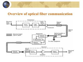
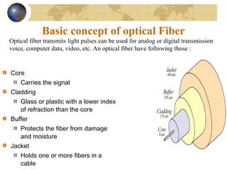
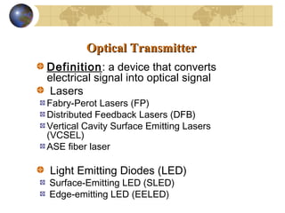
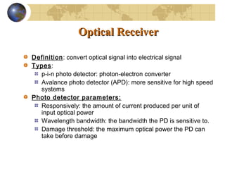
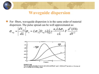
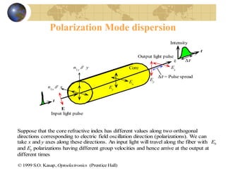
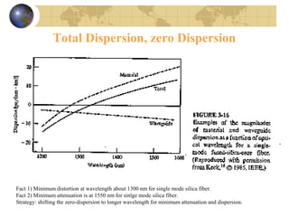
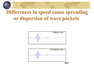
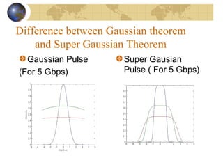
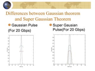
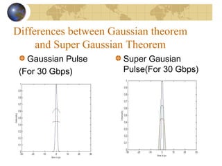
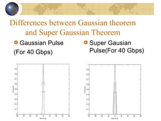
This document summarizes dispersion management in optical fiber communication. It discusses the basic components of an optical fiber including the core, cladding, buffer, and jacket. It also describes optical transmitters such as lasers and LEDs, as well as optical receivers such as photo detectors. The document outlines the main types of dispersion in fibers including material dispersion, waveguide dispersion, and polarization mode dispersion. It compares Gaussian and super Gaussian pulses and how super Gaussian pulses can reduce dispersion, especially at higher data transmission rates. In conclusion, the document provides a basic overview of optical fiber communication and dispersion management techniques.
This narrated power point presentation attempts to examine the losses due to non-linear effects in optical fibers. The material will be useful for KTU final year B Tech students who prepare for the subject EC 405, Optical Communications.
Basics of Optical amp, a brief explanation on how a Raman OP works.
You must know What is Scattering, stimulated and spontaneous emission in order to understand the basic principal of this OP amp.
Pump is also important which is the one that stimulates the energy to higher levels.
The attached narrated power point presentation attempts to explain the methods of computation of total power loss and system rise time in a fiber optic link. The material will be useful for KTU final year B Tech students who prepare for the subject EC 405, Optical Communications.
This narrated power point presentation attempts to explain the various dispersion mechanisms that are observed in optical fibers. Some fundamental terms and concepts are also discussed. The material will be useful for KTU final year B Tech students who prepare for the subject EC 405, Optical Communications.
The attached narrated power point presentation attempts to explain the working principle, types, classifications, merits, demerits, applications,safety and deployment issues related to Raman Amplifiers. The material will be useful for KTU final year B Tech students who prepare for the subject EC 405, Optical Communications.
Signal Degradation In Optical Fiber
Losses in an optical fibre:-
The types of losses in a optical fibre are
Attenuation loss
Absorption
Scattering
Bending loss
Dispersion loss
Coupling loss
LEDs are of interest for fibre optics because of five inherent characteristics..
How it works?
Spectrum of an LED
Modulation of LED
LED Vs. Laser diode
disadvantages of LED
Circuits for Optical Based Line of Sight Voice CommunicationjournalBEEI
We present here line of sight communication between a person and his neighbour with the help of optical signal produced by a laser torch which act as a carrier. It is therefore a wireless communication and the transmission can go up to 500 meters. We used photodiode to receive the signal at the receiver. The transmitter circuit comprises condenser microphone transistor amplifier BC547 followed by an op-amp stage built around µA741. When we give a voice signal from the mike, it converts the voice signal into the electrical signal. This electrical signal is fed to IC741 (op-amp) for amplification. The gain of the op-amp can be controlled with the help of 1-mega-ohm potentiometer. The AF output from IC is coupled to the base of a class B amplifier which, in turn, modulates the signal. The transmitter uses 5V power supply. However, the 3-volt laser torch (after removal of its battery) can be directly connected to the circuit-with the body of the torch connected to the class B. The photodiode converts the optical signal into electrical signal and again this signal is amplified using IC741 and a combination of class B push pull amplifiers. The receiver circuit uses an NPN photodiode as the light sensor that is followed by a two-stage transistor preamplifier and IC741 based audio Power amplifier. The receiver does not need any complicated alignment. Just keep the photodiode oriented towards the remote transmitter’s laser point and adjust the volume control for a clear sound. The sensor must not directly face the sun.
As we know Optical communication Network offers
very high potential bandwidth and flexibility. In terms of high
bit-rate transmission. However, their performance slows down
due to some parameter like dispersion, attenuation, scattering. In
long haul application, dispersion is the main parameter which
needs to be compensated in order to provide better service. Fiber
Braggs Grating (FBG) is one of the most widely used element to
compensate it, however its performance slows down with the
increase in distance.
This paper presents an investigation on Pulse distortions due to
the third-order dispersion (TOD) on very high speed long
distance single mode optical fiber communication system using
OptiSystem. Presence of the TOD introduces broadening on the
propagating pulse. The impact of TOD is observed at the
receiving end of transmission line considering the variation of
different factors such as transmission reach, bit rate, duty
cycle.BER performance are also considered here.
2. Presented by
Titas Kumer Sarker : 510
BSc in Electrical and Electronic Engineering
International Business Administration and
Information System University
Submitted To
Md Hasan Rahman
Lecturer
Department of Electrical and Electronic Engineering
International Business Administration and Information
System University
4. Basic concept of optical Fiber
Core
Carries the signal
Cladding
Glass or plastic with a lower index
of refraction than the core
Buffer
Protects the fiber from damage
and moisture
Jacket
Holds one or more fibers in a
cable
Optical fiber transmits light pulses can be used for analog or digital transmission
voice, computer data, video, etc. An optical fiber have following those :
5. Optical TransmitterOptical Transmitter
Definition: a device that converts
electrical signal into optical signal
Lasers
Fabry-Perot Lasers (FP)
Distributed Feedback Lasers (DFB)
Vertical Cavity Surface Emitting Lasers
(VCSEL)
ASE fiber laser
Light Emitting Diodes (LED)
Surface-Emitting LED (SLED)
Edge-emitting LED (EELED)
6. OpticalOptical ReceiverReceiver
Definition: convert optical signal into electrical signal
Types:
p-i-n photo detector: photon-electron converter
Avalance photo detector (APD): more sensitive for high speed
systems
Photo detector parameters:
Responsively: the amount of current produced per unit of
input optical power
Wavelength bandwidth: the bandwidth the PD is sensitive to.
Damage threshold: the maximum optical power the PD can
take before damage
7. Advantages of Optical Fiber
Thinner
Less Expensive
Higher Carrying Capacity
Less Signal Degradation& Digital Signals
Light Signals
Non-Flammable
Light Weight
8. Attenuation
Modern fiber material is very pure, but there is still some attenuation
The wavelengths used are chosen to avoid absorption bands
850 nm, 1300 nm, and 1550 nm
Plastic fiber uses 660 nm LEDs
• Image from iec.org (Link Ch 2n)
9. Dispersion
Dispersion is the spreading out of a light
pulse as it travels through the fiber
Three types:
Material Dispersion
Webguide Dispersion
Polarization Mode Dispersion (PMD)
11. Waveguide dispersion
For fibers, waveguide dispersion is in the same order of material
dispersion. The pulse spread can be well approximated as:
2
2
2 )(
)(
dV
Vbd
V
c
Ln
DL
d
d
wg
wg
wg
λ
σ
λσσ
λ
τ
σ λ
λλ
∆
==≈ )(λwgD
13. Total Dispersion, zero Dispersion
Fact 1) Minimum distortion at wavelength about 1300 nm for single mode silica fiber.
Fact 2) Minimum attenuation is at 1550 nm for sinlge mode silica fiber.
Strategy: shifting the zero-dispersion to longer wavelength for minimum attenuation and dispersion.
15. Difference between Gaussian theorem
and Super Gaussian Theorem
Gaussian Pulse
(For 5 Gbps)
Super Gausian
Pulse ( For 5 Gbps)
16. Difference between Gaussian theorem
and Super Gaussian Theorem
Gaussian Pulse
(For 10 Gbps)
Super Gausian
Pulse(For 10 Gbps)
17. Differences between Gaussian theorem
and Super Gaussian Theorem
Gaussian Pulse
(For 20 Gbps)
Super Gausian
Pulse(For 20 Gbps)
18. Differences between Gaussian theorem
and Super Gaussian Theorem
Gaussian Pulse
(For 30 Gbps)
Super Gausian
Pulse(For 30 Gbps)
19. Differences between Gaussian theorem
and Super Gaussian Theorem
Gaussian Pulse
(For 40 Gbps)
Super Gausian
Pulse(For 40 Gbps)
20. Conclusion
This concludes our study of Fiber Optics. We have looked at how
they work and how they are made. We have examined the
transmitter and receiver of fibers, and how fibers are work. Here
briefly explained attenuation and dispersion optical fiber. I have also
explained Gaussian Pulse and Super Gaussian Pulses. I got a sound
knowledge after that research if we use Super Gaussian Pulses
dispersion will be reduced. So that we should use Super Gaussian
pulse. Although this presentation does not cover all the aspects of
optical fiber work it will have equipped you knowledge and skills
essential to the fiber optic industry.
21. Thank you for your kind patience.
Have a nice time for all.....
How can I serve you?
Email : titasce@gmail.com.com
Skype : titasce