The document discusses considerations for wiring between an in-system programmer and a fixture for programming devices. Key points:
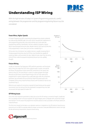
1) As programming speeds have increased, careful wiring is needed to avoid signal degradation over the distances involved.
2) Modern devices only require a few programming lines, but memory sizes are increasing rapidly, requiring higher communication bit rates over the wiring.
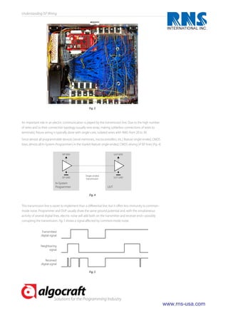
3) Wiring lengths over 50cm can degrade signal integrity for some programming protocols. The programmer should be placed as close to the fixture as possible.
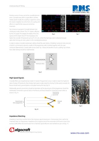
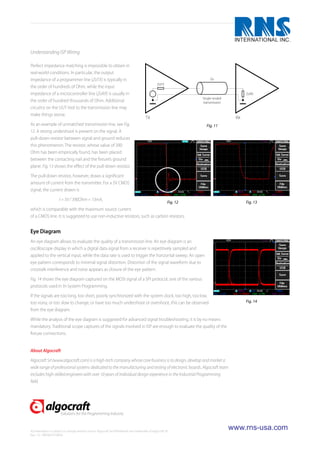
4) Noise and crosstalk between wires must be minimized through techniques like twisted pair cabling, ground planes, and redundant ground connections. Impedance matching is also important for signal
IJRET : International Journal of Research in Engineering and Technology is an international peer reviewed, online journal published by eSAT Publishing House for the enhancement of research in various disciplines of Engineering and Technology. The aim and scope of the journal is to provide an academic medium and an important reference for the advancement and dissemination of research results that support high-level learning, teaching and research in the fields of Engineering and Technology. We bring together Scientists, Academician, Field Engineers, Scholars and Students of related fields of Engineering and Technology.
IOSR Journal of Electronics and Communication Engineering(IOSR-JECE) is an open access international journal that provides rapid publication (within a month) of articles in all areas of electronics and communication engineering and its applications. The journal welcomes publications of high quality papers on theoretical developments and practical applications in electronics and communication engineering. Original research papers, state-of-the-art reviews, and high quality technical notes are invited for publications.
A Simulation of Wideband CDMA System on Digital Up/Down ConvertersEditor IJMTER
In this paper, I present FPGA implementation of a digital down converter (DDC) and
digital up converter (DUC) for a single carrier WCDMA system. The DDC and DUC is complex in
nature. The implementation of DDC is simple because it does not require mixers or filters. Xilinx
System Generator and Xilinx ISE are used to develop the hardware circuit for the FPGA. Both the
circuits are verified on the Spartan - 3 FPGA
Implementation and Test of a Power-Line based Communication System for Elect...Valerio Aisa
This paper discusses the development of a low-cost, narrow-band transmission system, aimed at connecting digital appliances to a home network. The proposed approach is based on powerline communication (ULP: Ultra Low-cost Powerline), carried out on the power-supply wire between the appliance and the outlet. Through ULP, appliance can communicate with a transceiver node located at the outlet, the “smart adapter”, which, in turn, can flexibly route messages toward external control devices (e.g., for diagnostic purposes) or, more generally, toward a home control network. At the appliance side, such an approach allows for connectivity at extremely low costs, at the same time keeping independent of the actual home control network protocol (since different configurations of the smart adapter take care of it). To make practical their implementation on a variety of digital appliances, ULP communication functions have been implemented in a dedicated hardware device, conceived as a dedicated peripheral for a general-purpose microcontroller. In this work, details on the peripheral architecture and its implementation are given. A prototype of the peripheral has been developed, based on a FPGA board directly connected to the microprocessor bus. This closely emulates the perspective microcontroller architecture, and allowed for extensive testing of the device under realistic operating conditions.
Connecting electrical appliances to a Home Network using low-cost Power-Line ...Valerio Aisa
This paper discusses a novel “proxy” approach, aimed at connecting digital appliances to a home network and based on ultra low cost, narrow band power-line transmission (ULP). Bidirectional point-to-point communication is carried out on power-supply wire between the appliance itself and the outlet.
Here a dedicated device embeds both network management functions and ULP communication, acting as a proxy between the appliance and the home network. Through this approach, white goods and any other electrical household appliance can be connected to the home network at extremely low communication cost and without issues related to standard protocol selection. In this summary, after a brief introduction, the network structure is presented. Next, physical layer of ULP protocol is discussed and a prototypal HW implementation is presented. Finally, experimental ULP performances are discussed and conclusions are drawn. (Presented at ISPLC 2005)
Significant amount of research and development has been made in the field of core network and it operates in hundreds Gigabits per second (Gbps) speed currently. But on seeing the growth in bandwidth demand in the access network which is exploding day by day, the only promising solution is to upgrade the access network. So it is essential to have an efficient access network that can operate at high functional speeds to support differentiated services like Video on Demand (VOD), High Definition TV, video conferencing, Telemedicine, Uploading and Downloading jumbo files. Apart from these access network always been sensitive to cost and geographical region of coverage it can handle. So internet service providers will have to make a tradeoff between capital expenditure (CAPEX), operational expenditure (OPEX) and geographical region of coverage.
There are mainly five types of access network APON, BPON, GPON, EPON and 10G-EPON. APON provides 622 Mbps of downstream bandwidth and 155 Mbps of upstream. GPON was the advanced version of the BPON and support at a rate of 2.444 Mbps and 1.42 Mbps in downstream and upstream data rate. EPON has symmetry of 1Gbps of upstream and downstream rates. EPON is totally data-centric based on voice, video and data. 10G-EPON is capable of providing broadband access to large number of customers in metropolitan area. Due to the advancement in the optical technology, 10G-EPON (IEEE 803.2av) provides 1Gbps and 10Gbps upstream and downstream data rate with distance more than 20 km.
Performance Improvement of IEEE 802.22 WRAN Physical LayerIOSR Journals
The spectrum available for the wireless services is limited, the increased demand of wireless
application has put a lot of limitations on the utilization of available radio spectrum. For the efficient spectrum
utilization for wireless application IEEE 802.22 standard i.e. WRAN (Wireless Regional Area Network) is
developed which is based on cognitive radio technique that senses the free available spectrum. It allows sharing
of geographically unused channels allocated to the TV Broadcast Service, without interference.
In this paper we are evaluating the performance of WRAN over physical layer with QPSK, 16-QAM
and 64-QAM modulation with Convolution coding with code rate of 1/2, 2/3, 3/4, 5/6 and obtaining the BER
curves for rician channel. Simulation is performed in MATLAB
Performance Improvement of IEEE 802.22 WRAN Physical LayerIOSR Journals
Abstract: The spectrum available for the wireless services is limited, the increased demand of wireless application has put a lot of limitations on the utilization of available radio spectrum. For the efficient spectrum utilization for wireless application IEEE 802.22 standard i.e. WRAN (Wireless Regional Area Network) is developed which is based on cognitive radio technique that senses the free available spectrum. It allows sharing of geographically unused channels allocated to the TV Broadcast Service, without interference. In this paper we are evaluating the performance of WRAN over physical layer with QPSK, 16-QAM and 64-QAM modulation with Convolution coding with code rate of 1/2, 2/3, 3/4, 5/6 and obtaining the BER curves for rician channel. Simulation is performed in MATLAB. Keywords - CC, CP, CR, OFDMA, PHY Layer, WRAN
Performance Improvement of IEEE 802.22 WRAN Physical LayerIOSR Journals
Abstract: The spectrum available for the wireless services is limited, the increased demand of wireless
application has put a lot of limitations on the utilization of available radio spectrum. For the efficient spectrum
utilization for wireless application IEEE 802.22 standard i.e. WRAN (Wireless Regional Area Network) is
developed which is based on cognitive radio technique that senses the free available spectrum. It allows sharing
of geographically unused channels allocated to the TV Broadcast Service, without interference.
In this paper we are evaluating the performance of WRAN over physical layer with QPSK, 16-QAM
and 64-QAM modulation with Convolution coding with code rate of 1/2, 2/3, 3/4, 5/6 and obtaining the BER
curves for rician channel. Simulation is performed in MATLAB.
Keywords - CC, CP, CR, OFDMA, PHY Layer, WRAN
Design of Low Power High Speed 4-Bit TIQ Based CMOS Flash ADCAman JanGra
The analog-to-digital converter (ADC) is an essential part of systemon-
chip (SoC) products because it bridges the gap between the analog physical
world and the digital logical world. In the digital domain, low power and low
voltage requirements are becoming more important issues as the channel length
of MOSFET shrinks below 0.25 sub-micron values. SoC trends force ADCs to
be integrated on the chip with other digital circuits. These trends present new
challenges in ADC circuit design. This paper investigates high speed, low
power, and low voltage CMOS flash ADCs for SoC applications.
IJERA (International journal of Engineering Research and Applications) is International online, ... peer reviewed journal. For more detail or submit your article, please visit www.ijera.com
-Study of the functionality of 2MB mother board, providing E1 data interfaces
-CMS LAB,TEST EQUIPMENT, QUALITY CONTROL. - ABOUT BEL,ROTATIONAL PROGRAM.-FPGA,ADSP,DSO,VHDL.
-E1 EUROPEAN DATA FORMAT , LINK, SPECIFICATION
ENCODING TECHNIQUES- HDB3, AMI
Skye Residences | Extended Stay Residences Near Toronto Airportmarketingjdass
Experience unparalleled EXTENDED STAY and comfort at Skye Residences located just minutes from Toronto Airport. Discover sophisticated accommodations tailored for discerning travelers.
Website Link :
https://skyeresidences.com/
https://skyeresidences.com/about-us/
https://skyeresidences.com/gallery/
https://skyeresidences.com/rooms/
https://skyeresidences.com/near-by-attractions/
https://skyeresidences.com/commute/
https://skyeresidences.com/contact/
https://skyeresidences.com/queen-suite-with-sofa-bed/
https://skyeresidences.com/queen-suite-with-sofa-bed-and-balcony/
https://skyeresidences.com/queen-suite-with-sofa-bed-accessible/
https://skyeresidences.com/2-bedroom-deluxe-queen-suite-with-sofa-bed/
https://skyeresidences.com/2-bedroom-deluxe-king-queen-suite-with-sofa-bed/
https://skyeresidences.com/2-bedroom-deluxe-queen-suite-with-sofa-bed-accessible/
#Skye Residences Etobicoke, #Skye Residences Near Toronto Airport, #Skye Residences Toronto, #Skye Hotel Toronto, #Skye Hotel Near Toronto Airport, #Hotel Near Toronto Airport, #Near Toronto Airport Accommodation, #Suites Near Toronto Airport, #Etobicoke Suites Near Airport, #Hotel Near Toronto Pearson International Airport, #Toronto Airport Suite Rentals, #Pearson Airport Hotel Suites
Attending a job Interview for B1 and B2 Englsih learnersErika906060
It is a sample of an interview for a business english class for pre-intermediate and intermediate english students with emphasis on the speking ability.
RMD24 | Debunking the non-endemic revenue myth Marvin Vacquier Droop | First ...BBPMedia1
Marvin neemt je in deze presentatie mee in de voordelen van non-endemic advertising op retail media netwerken. Hij brengt ook de uitdagingen in beeld die de markt op dit moment heeft op het gebied van retail media voor niet-leveranciers.
Retail media wordt gezien als het nieuwe advertising-medium en ook mediabureaus richten massaal retail media-afdelingen op. Merken die niet in de betreffende winkel liggen staan ook nog niet in de rij om op de retail media netwerken te adverteren. Marvin belicht de uitdagingen die er zijn om echt aansluiting te vinden op die markt van non-endemic advertising.
India Orthopedic Devices Market: Unlocking Growth Secrets, Trends and Develop...Kumar Satyam
According to TechSci Research report, “India Orthopedic Devices Market -Industry Size, Share, Trends, Competition Forecast & Opportunities, 2030”, the India Orthopedic Devices Market stood at USD 1,280.54 Million in 2024 and is anticipated to grow with a CAGR of 7.84% in the forecast period, 2026-2030F. The India Orthopedic Devices Market is being driven by several factors. The most prominent ones include an increase in the elderly population, who are more prone to orthopedic conditions such as osteoporosis and arthritis. Moreover, the rise in sports injuries and road accidents are also contributing to the demand for orthopedic devices. Advances in technology and the introduction of innovative implants and prosthetics have further propelled the market growth. Additionally, government initiatives aimed at improving healthcare infrastructure and the increasing prevalence of lifestyle diseases have led to an upward trend in orthopedic surgeries, thereby fueling the market demand for these devices.
Remote sensing and monitoring are changing the mining industry for the better. These are providing innovative solutions to long-standing challenges. Those related to exploration, extraction, and overall environmental management by mining technology companies Odisha. These technologies make use of satellite imaging, aerial photography and sensors to collect data that might be inaccessible or from hazardous locations. With the use of this technology, mining operations are becoming increasingly efficient. Let us gain more insight into the key aspects associated with remote sensing and monitoring when it comes to mining.
Discover the innovative and creative projects that highlight my journey throu...dylandmeas
Discover the innovative and creative projects that highlight my journey through Full Sail University. Below, you’ll find a collection of my work showcasing my skills and expertise in digital marketing, event planning, and media production.
The world of search engine optimization (SEO) is buzzing with discussions after Google confirmed that around 2,500 leaked internal documents related to its Search feature are indeed authentic. The revelation has sparked significant concerns within the SEO community. The leaked documents were initially reported by SEO experts Rand Fishkin and Mike King, igniting widespread analysis and discourse. For More Info:- https://news.arihantwebtech.com/search-disrupted-googles-leaked-documents-rock-the-seo-world/
Falcon stands out as a top-tier P2P Invoice Discounting platform in India, bridging esteemed blue-chip companies and eager investors. Our goal is to transform the investment landscape in India by establishing a comprehensive destination for borrowers and investors with diverse profiles and needs, all while minimizing risk. What sets Falcon apart is the elimination of intermediaries such as commercial banks and depository institutions, allowing investors to enjoy higher yields.
1. Understanding ISP Wiring
With the high bit rates of today’s In-System Programming protocols, careful
wiring between the programmer and the programming/testing xture must be
considered.
Fewer Wires, Higher Speeds Number of
ISP Lines
In-System Programming (ISP) is becoming the programming solution preferred
by small and big OEM/EMS alike. Since each silicon manufacturer implements its
8
own programming protocol(s), every device family has its own particular
programming interface. Nonetheless, the lines needed to program a typical
device have decreased during the years. Modern devices only need very few lines 4
to be programmed; in some cases, just one line is needed (Fig. 1).
At the same time, the devices’ non-volatile memory is rapidly increasing (Fig. 2).
1
To keep programming times low, the ISP lines must therefore be capable of
sustaining higher communication bit rates. Higher bit rates mean that the wiring
of the ISP lines inside the programming/testing xture has to be carefully
thought. 1990 2000 2010 Year
Fig. 1
Fixture Wiring
Device
Usually, an Automatic Test Equipment (ATE) performs parametric and functional Memory
tests on the Unit Under Test (UUT) that is placed inside a custom, unit-speci c (KB)
test xture. The text xture routes several ATE control lines to the various test
1000
points on the UUT. The same xture is used to in-system program the target
device(s) (or DUP, Device Under Programming) in the UUT that needs to be
programmed. In-system programming usually takes place after the component 100
parametric test and before the functional test. Multi-PCB panels add to the
complexity of the wiring inside the xture; xtures with hundreds of nails are not
uncommon (Fig. 3). 10
While the vast majority of connections required for board testing are low-speed
transmission lines, the wiring of the lines dedicated to programming must take
into account the high speed of modern ISP. 1990 2000 2010 Year
Fig. 2
ISP Wiring Issues
One of the most important parameters to take into account for ISP wiring is connection length. Usually (but
this is not always known to the test engineer), ISP signal integrity starts to degrade with connections longer
than 40-50cm. For this reason the programmer should be placed as near as possible to the xture, better yet
inside the xture.
The 50cm limit should not be taken as an absolute maximum: it depends on the ISP protocol. Asynchronous
protocols such as UART, for example, allow for longer connections; Freescale’s BDM protocol, due to the high
bit rate and driving characteristics, requires shorter wiring.
Solutions for the Programming Industry
www.rnsusa.com
2. Understanding ISP Wiring
Fig. 3
An important role in an electric communication is played by the transmission line. Due to the high number
of wires and to their connection typology (usually wire wrap, making solderless connections of wires to
terminals), xture wiring is typically done with single-core, isolated wires with AWG from 20 to 30.
Since almost all programmable devices (serial memories, microcontrollers, etc.) feature single-ended, CMOS
lines, almost all In-System Programmers in the market feature single-ended, CMOS driving of ISP lines (Fig. 4).
ISP VDD UUT VDD
Single-ended
ISP GND UUT GND
transmission
In-System
Programmer UUT
Fig. 4
This transmission line is easier to implement than a di erential line, but it o ers less immunity to common-
mode noise. Programmer and DUP usually share the same ground potential and, with the simultaneous
activity of several digital lines, electric noise will add both on the transmitter and receiver end—possibly
corrupting the transmission. Fig. 5 shows a signal a ected by common-mode noise.
Transmitted
digital signal
Neighboring
signal
Received
digital signal
Fig. 5
Solutions for the Programming Industry
www.rnsusa.com
3. Understanding ISP Wiring
Another source of noise can be the crosstalk phenom-
enon. Crosstalk arises when a signal a ects another
nearby signal. Usually the coupling is capacitive, and to
the nearest neighbor, but other forms of coupling and
e ects on signal further away are sometimes
important.
Fig. 6 shows an example of crosstalk between two
conductors inside a xture. The CH1 signal is a ected
by the CH2 signal. The steeper the edges of the CH2 Fig. 6 Fig. 7
signal, and the higher the CH1 line impedance, the
higher the crosstalk. ISP protocols such as I2C, ICC, etc., where the high logic state is obtained through
open-drain driving, are more subject to the crosstalk phenomenon.
In order to reduce crosstalk, twisted pair cabling should be used, where a “shielding” conductor (only one end
of which is connected to ground, usually on the programmer side) is twisted together with the main
conductor (alternatively, a coaxial cable can be used). Fig. 7 shows the bene ts of such a cabling. Fig. 8 shows
how cable twisting should be implemented.
ISP VDD UUT VDD
Twisted pair cabling
ISP GND UUT GND
In-System
Programmer UUT
Fig. 8
High-Speed Signals
Crosstalk e ects are empathized by modern In-System Programmers since, in order to reach the higher bit Ground Plane
rates of today’s ISP protocols, they employ high-speed single ended line driving. To help avoid crosstalk, the
xture should have a ground plane on the plate hosting the nails (Fig. 9).
Additionally, ground connections should be redundant; all the ground pins of the programmer should be
individually connected to ground nails on the xture, and these should be connected to each other, as
shown in Fig. 10. Ground wiring
connecting all
ground nails
Ground wires Ground
from programmer nails
Fig. 9
Fig. 10
Impedance Matching
Impedance matching is another factor that improves signal transmission. A transmission line is said to be
“matched” when its characteristic impedance (Zo) is equal to that of the transmitter (ZoTX) and to that of the
receiver (ZoRX). When the transmission line is matched, signal re ection and interferences are null (Fig. 11).
Solutions for the Programming Industry
www.rnsusa.com
4. Understanding ISP Wiring
Perfect impedance matching is impossible to obtain in
real-world conditions. In particular, the output
impedance of a programmer line (ZoTX) is typically in Zo
ZoTX
the order of hundreds of Ohm, while the input
impedance of a microcontroller line (ZoRX) is usually in ZoRX
Single-ended
the order of hundred thousands of Ohm. Additional transmission
circuitry on the UUT tied to the transmission line may
make things worse.
TX RX
As an example of unmatched transmission line, see Fig. Fig. 11
12. A strong undershoot is present on the signal. A
pull-down resistor between signal and ground reduces
this phenomenon. The resistor, whose value of 390
Ohm has been empirically found, has been placed
between the contacting nail and the xture’s ground
plane. Fig. 13 shows the e ect of the pull-down resistor.
The pull-down resistor, however, draws a signi cant
amount of current from the transmitter. For a 5V CMOS
signal, the current drawn is
I = 5V / 390Ohm = 13mA,
Fig. 12 Fig. 13
which is comparable with the maximum source current
of a CMOS line. It is suggested to use non-inductive resistors, such as carbon resistors.
Eye Diagram
An eye diagram allows to evaluate the quality of a transmission line. An eye diagram is an
oscilloscope display in which a digital data signal from a receiver is repetitively sampled and
applied to the vertical input, while the data rate is used to trigger the horizontal sweep. An open
eye pattern corresponds to minimal signal distortion. Distortion of the signal waveform due to
crosstalk interference and noise appears as closure of the eye pattern.
Fig. 14 shows the eye diagram captured on the MOSI signal of a SPI protocol, one of the various
protocols used in In-System Programming.
If the signals are too long, too short, poorly synchronized with the system clock, too high, too low,
too noisy, or too slow to change, or have too much undershoot or overshoot, this can be observed Fig. 14
from the eye diagram.
While the analysis of the eye diagram is suggested for advanced signal troubleshooting, it is by no means
mandatory. Traditional scope captures of the signals involved in ISP are enough to evaluate the quality of the
xture connections.
About Algocraft
Algocraft Srl (www.algocraft.com) is a high-tech company whose core business is to design, develop and market a
wide range of professional systems dedicated to the manufacturing and testing of electronic boards. Algocraft team
includes high-skilled engineers with over 10 years of individual design experience in the Industrial Programming
eld.
Solutions for the Programming Industry
All information is subject to change without notice. Algocraft and WriteNow! are trademarks of Algocraft Srl.
www.rnsusa.com
Rev. 1.0 - WP00010100EN