Downloaded 298 times
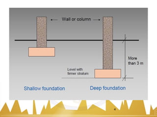
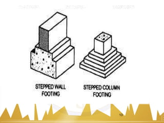
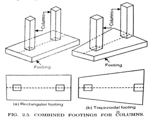
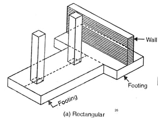
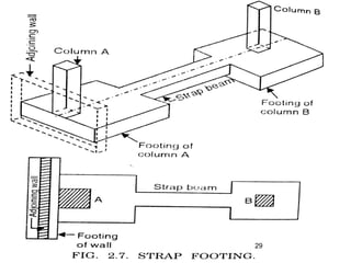
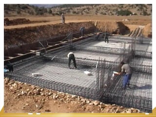
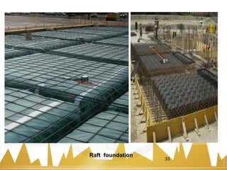


The document discusses different types of shallow foundations. It describes spread footings, combined footings, strap footings, and mat or raft foundations. For spread footings, it provides details on single, stepped, sloped, wall, and grillage footings. Foundations are also discussed for black cotton soils, including strip footings, pier foundations, and under-reamed pile foundations. Finally, potential causes of foundation failure are listed such as unequal settlement, subsoil moisture movement, and lateral soil pressures.


