Download as PDF, PPTX
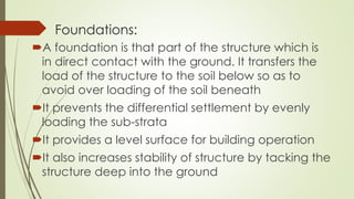
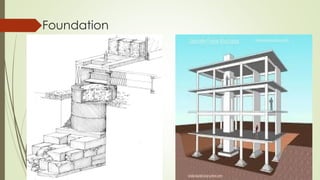
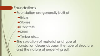
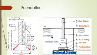
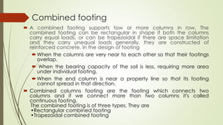
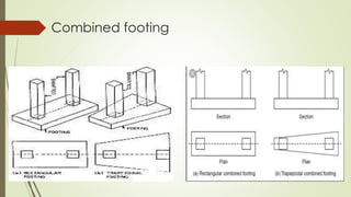
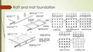

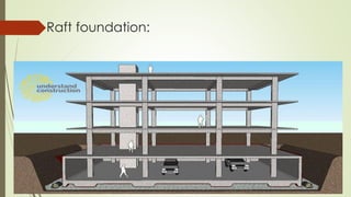
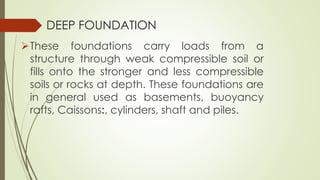
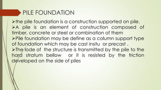


The document discusses the construction and significance of building foundations, explaining their role in transferring loads from structures to the soil and preventing differential settlement. It categorizes foundations into shallow and deep types, detailing various common forms including spread footing, combined footing, and raft foundations. Additionally, it covers different materials used for foundations, such as concrete, steel, and timber, and the considerations for selecting foundation types based on soil conditions and structural requirements.


