Downloaded 1,974 times

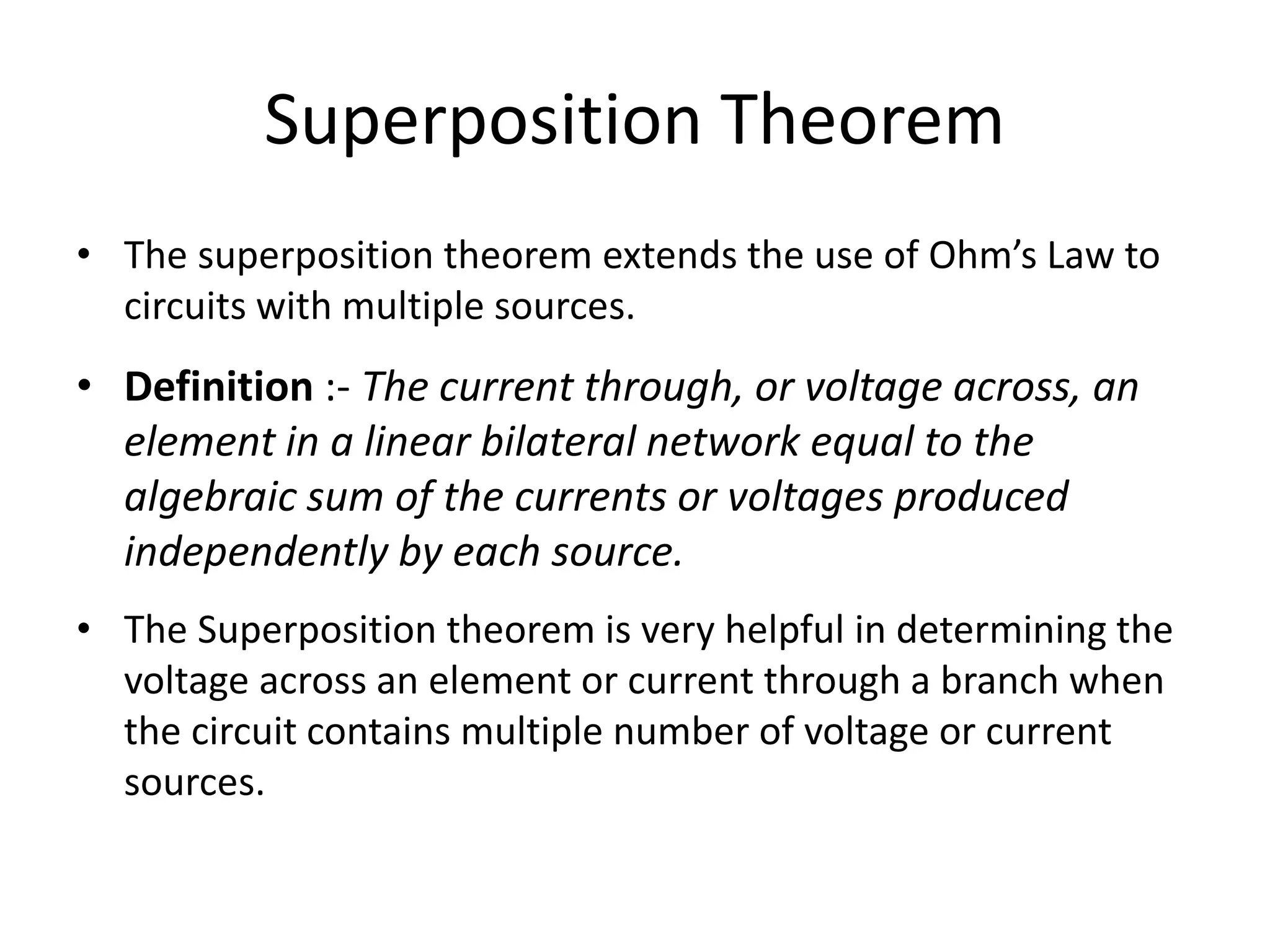
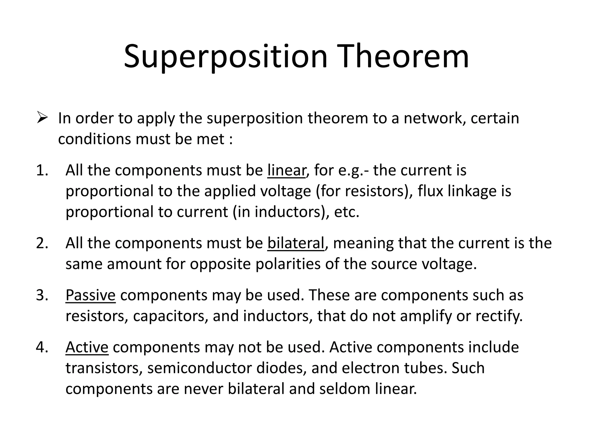
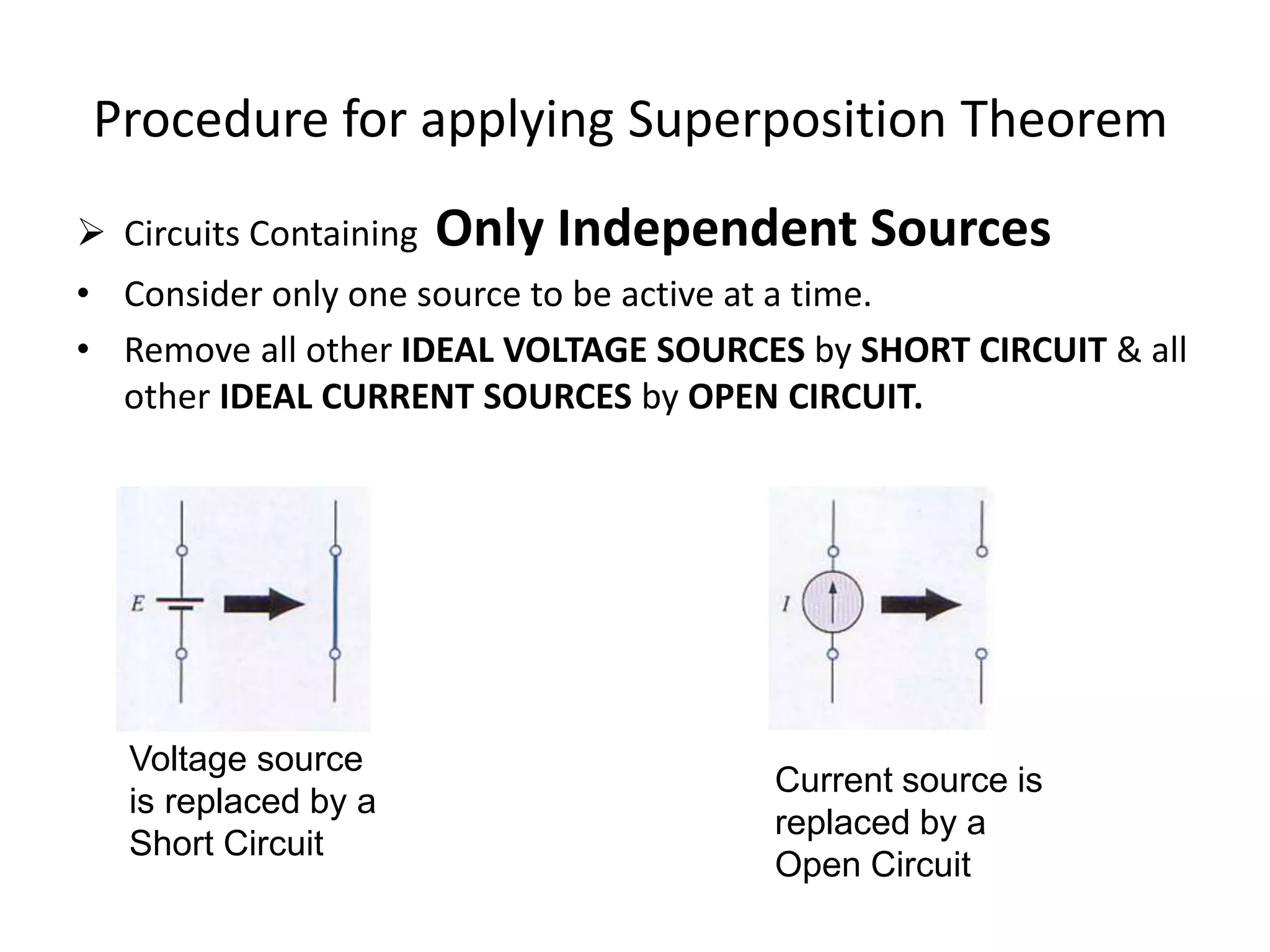
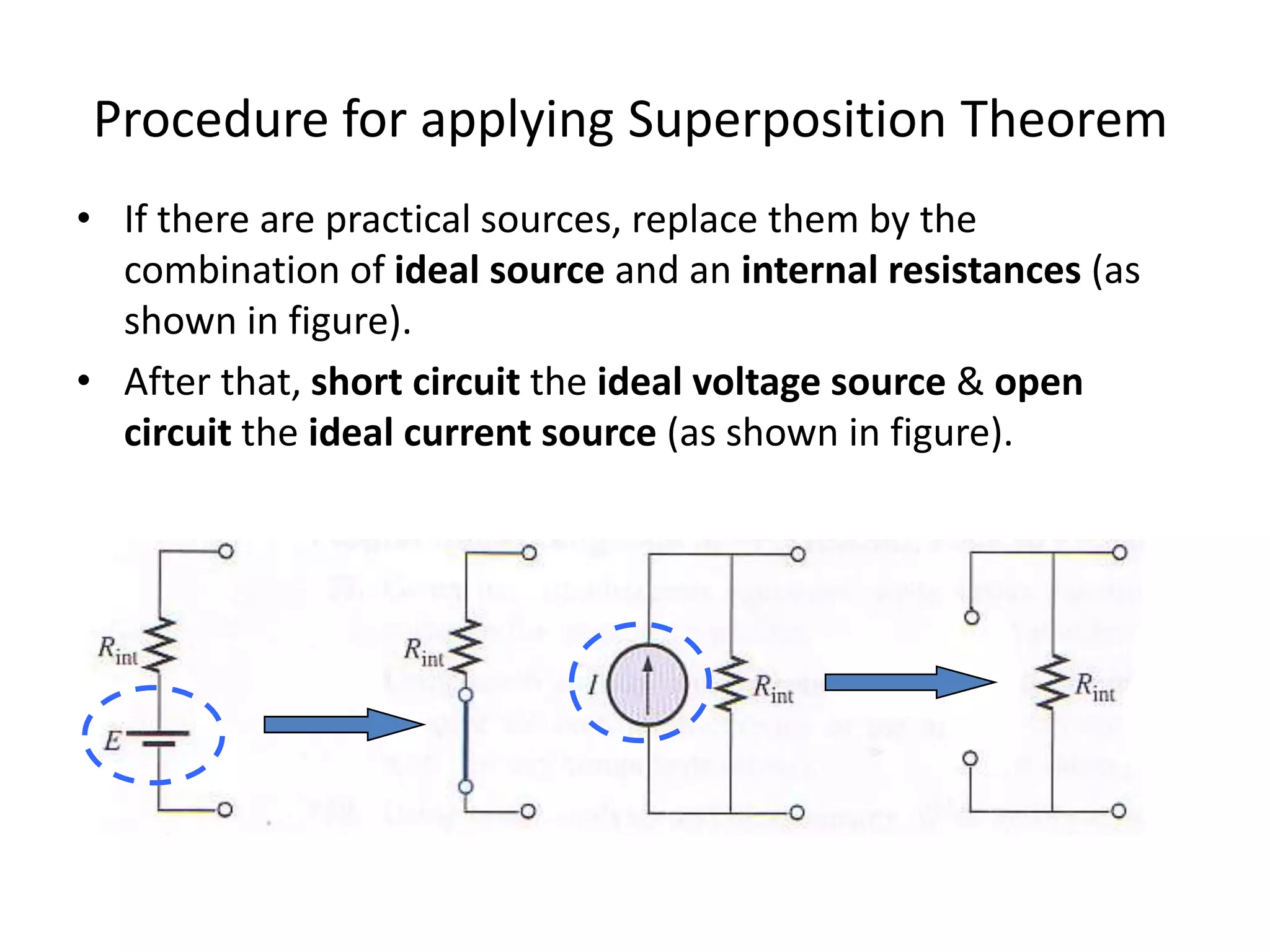
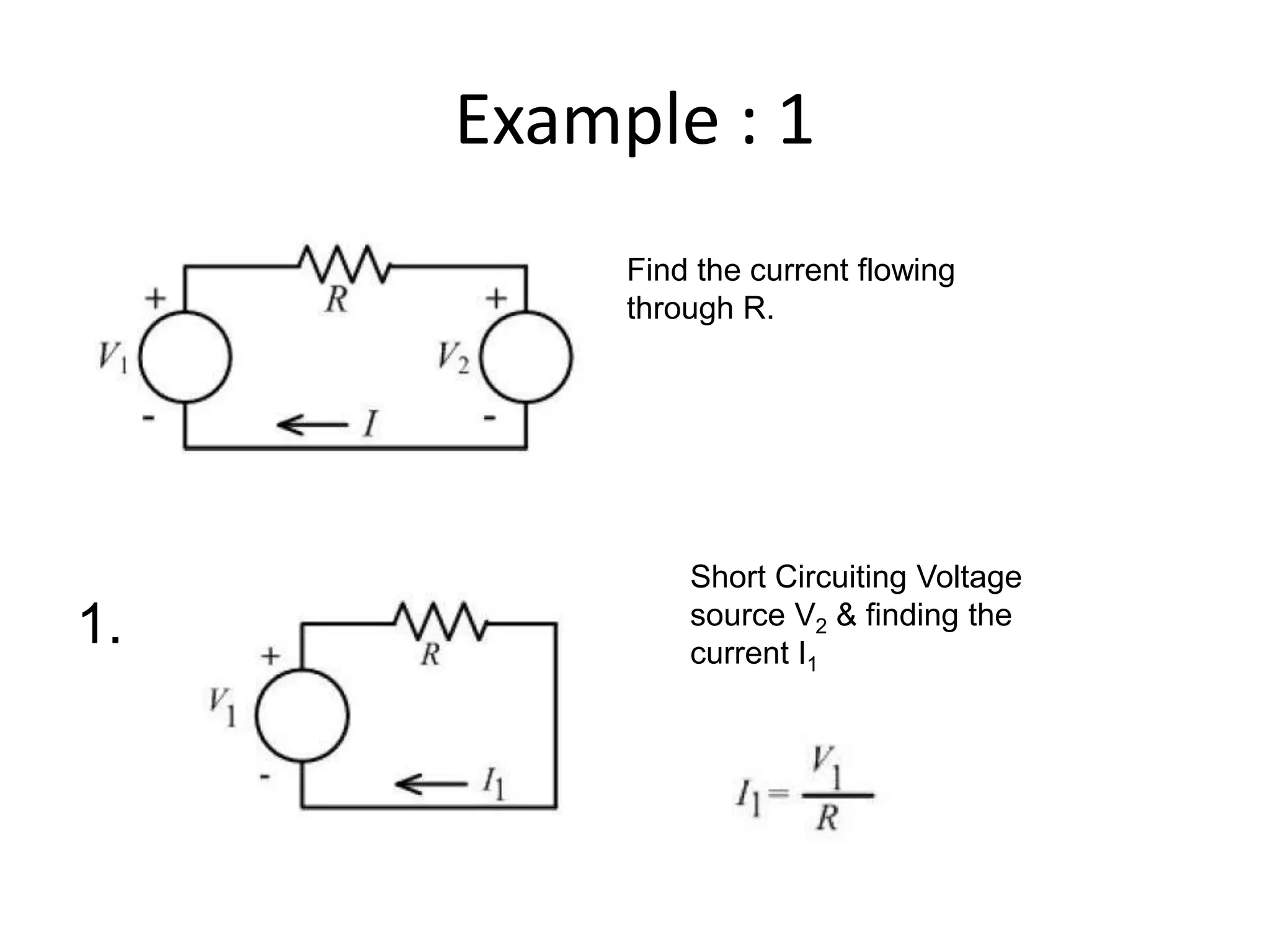
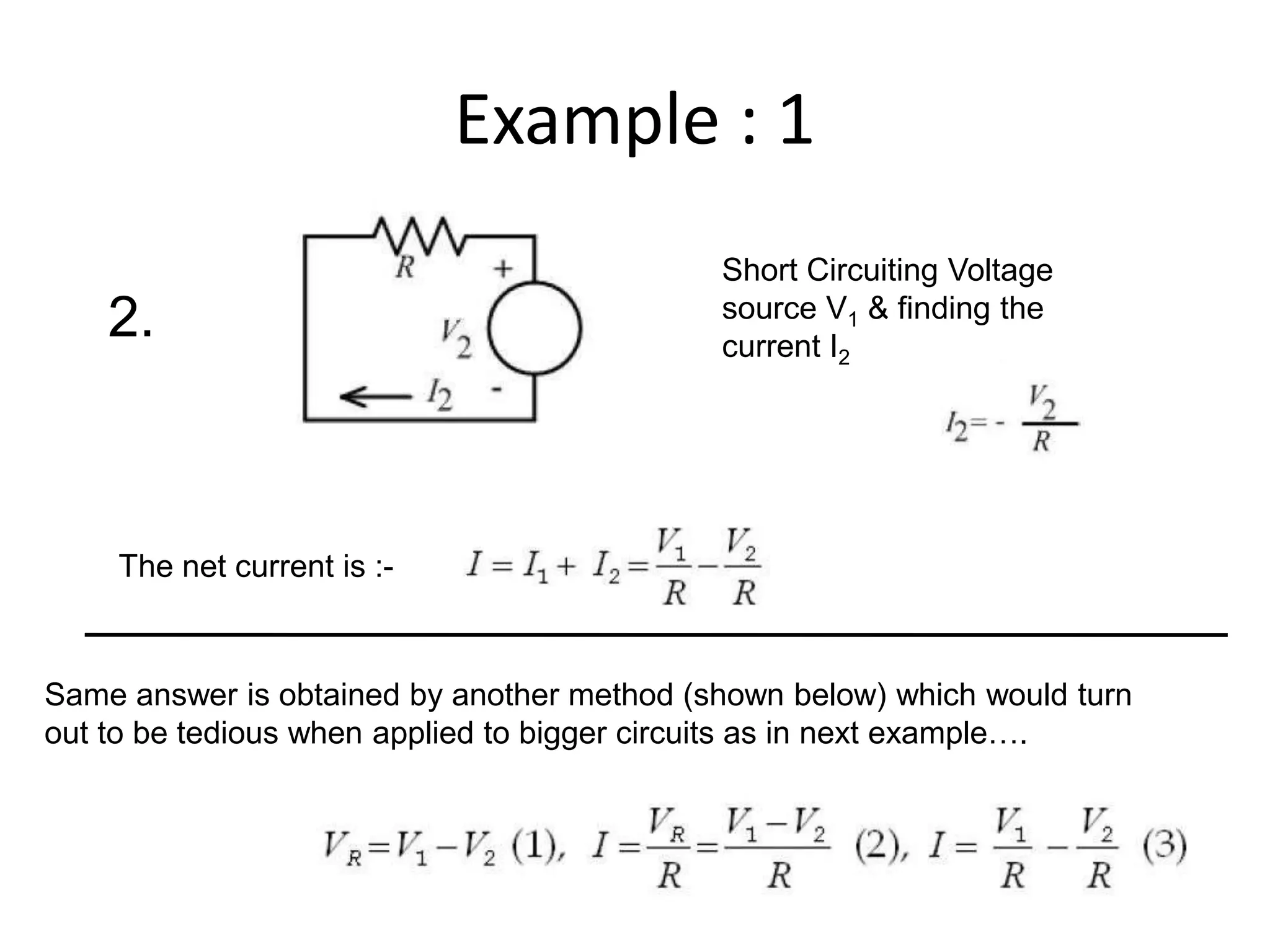

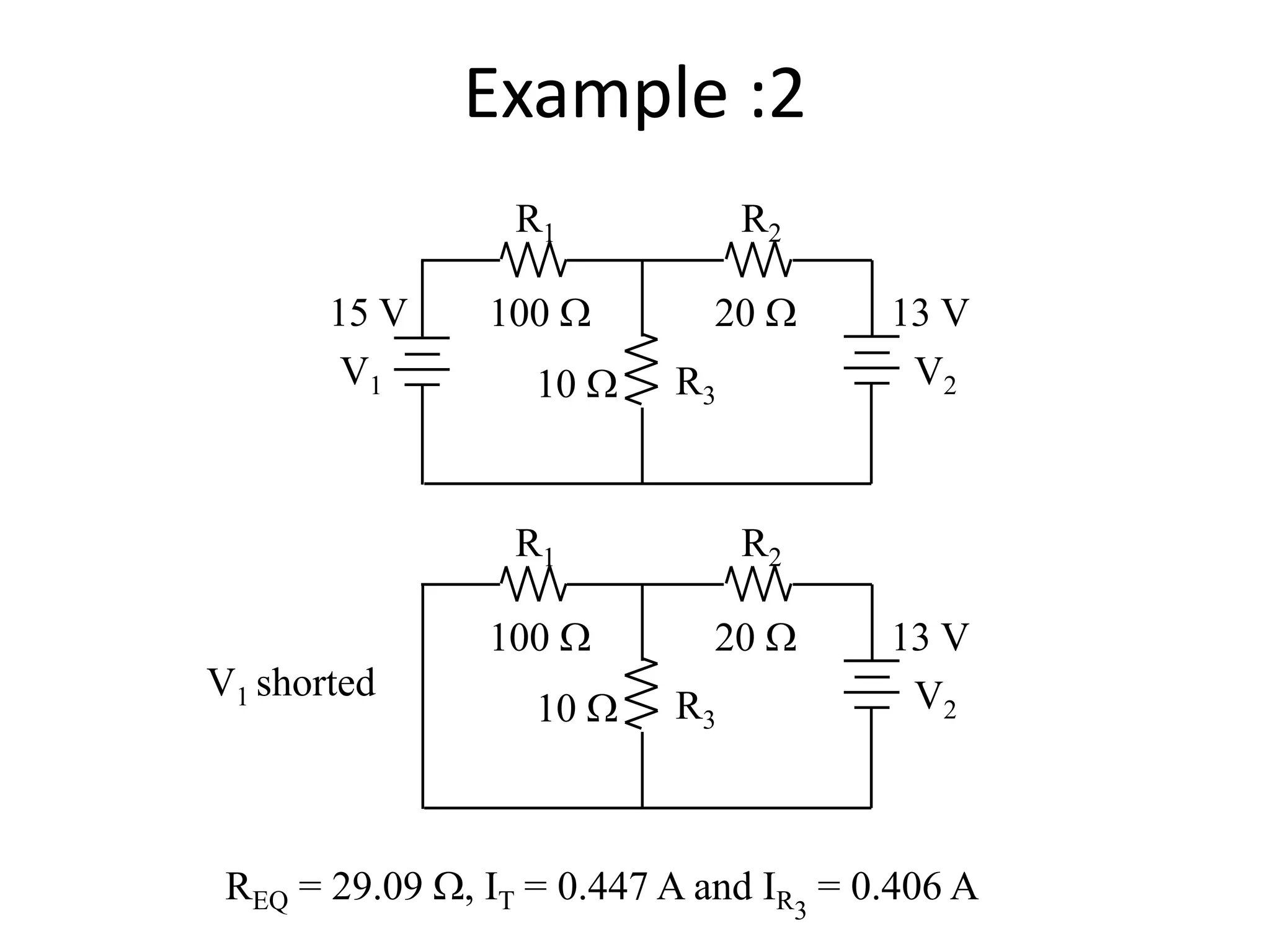
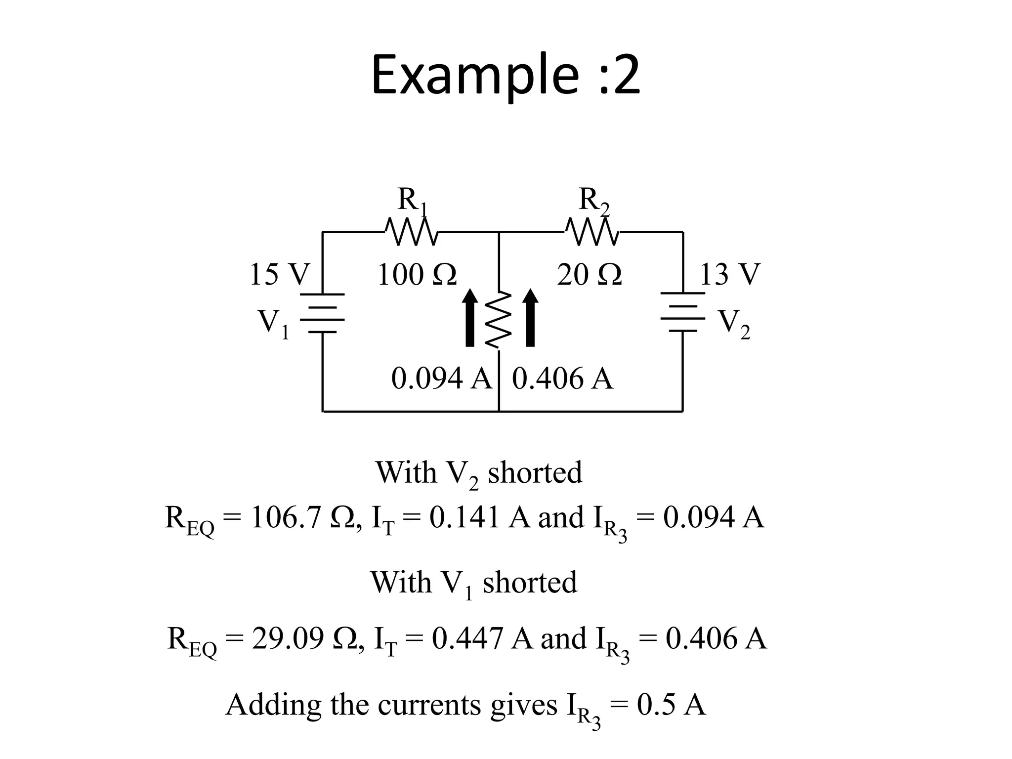

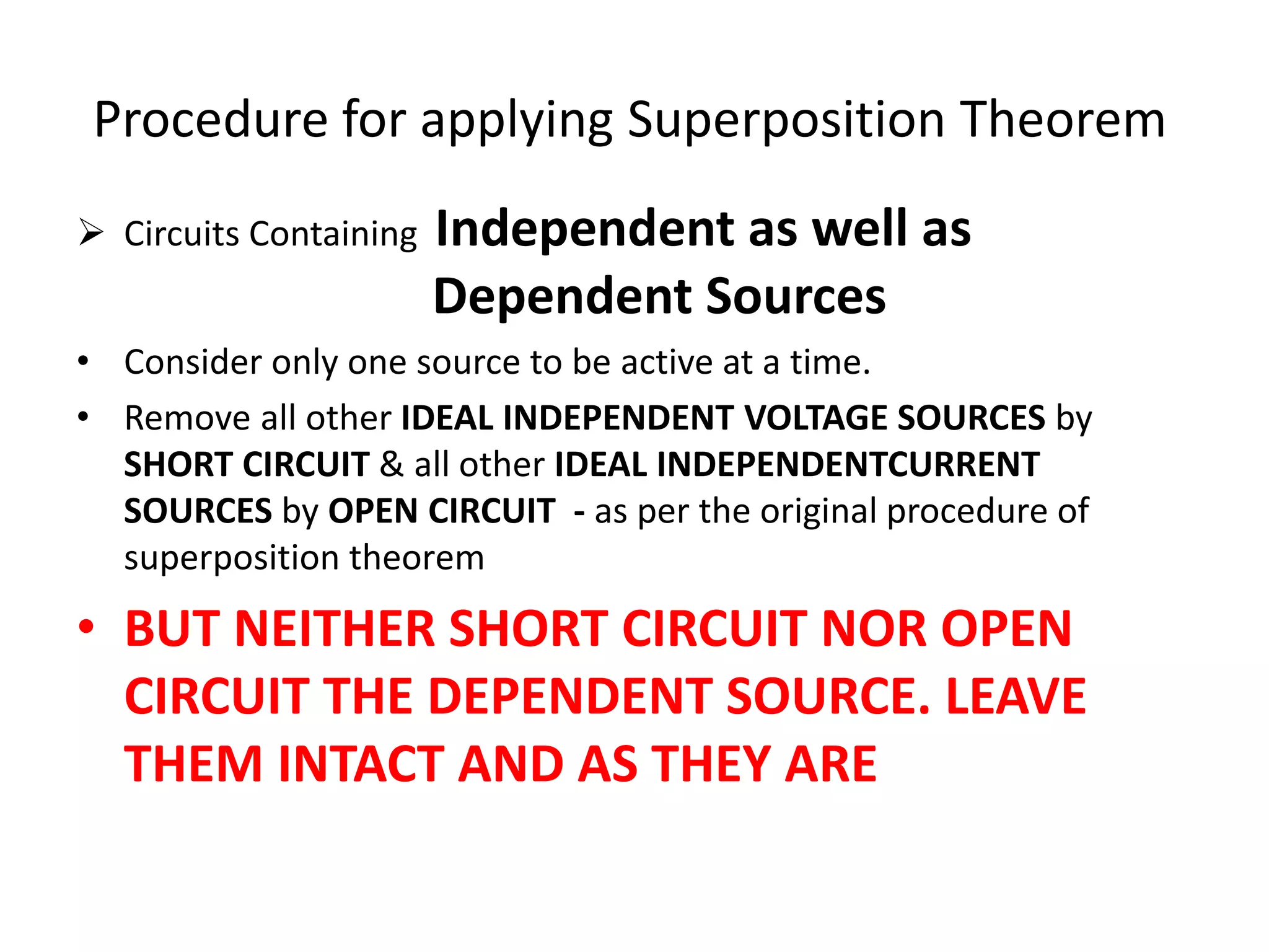
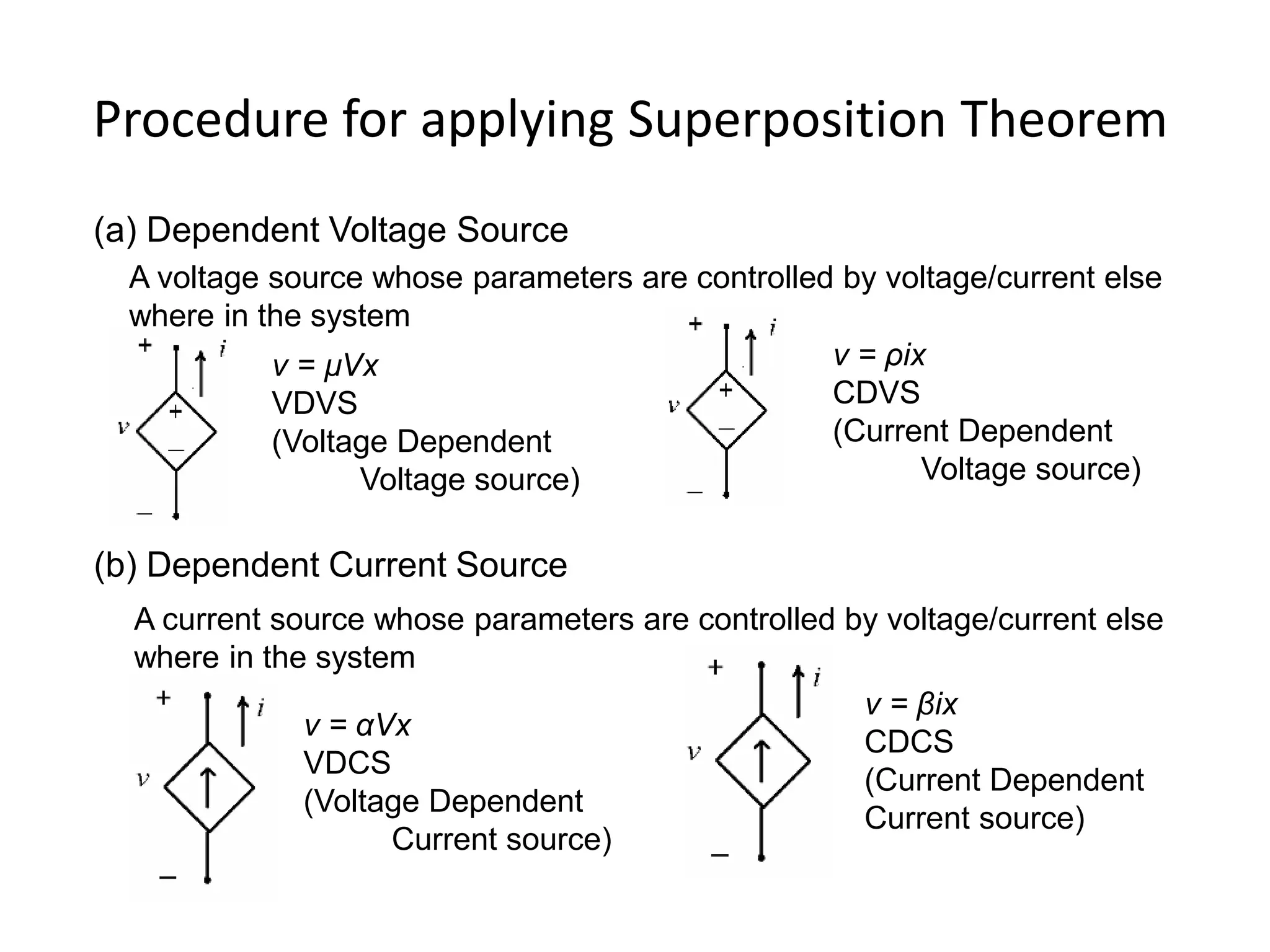
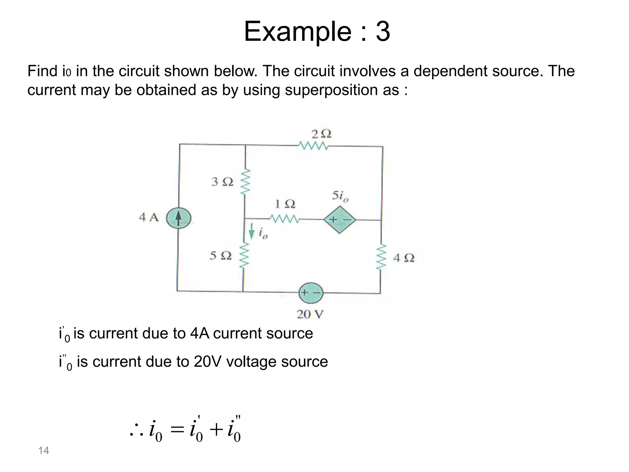

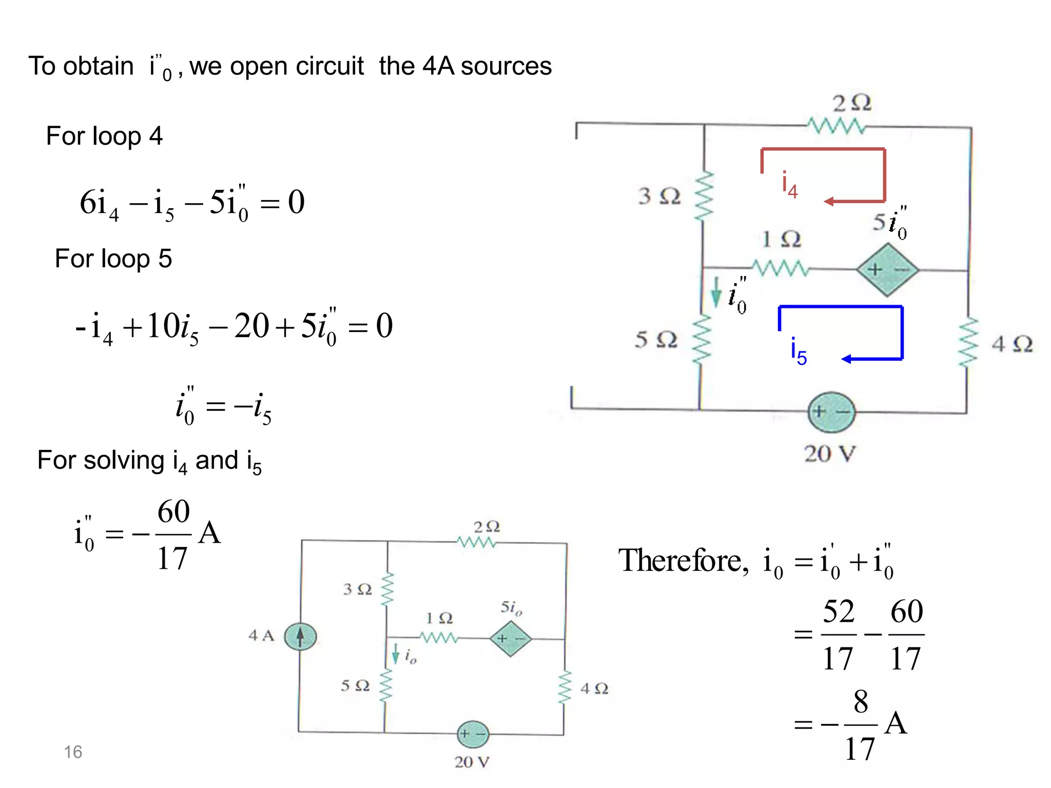
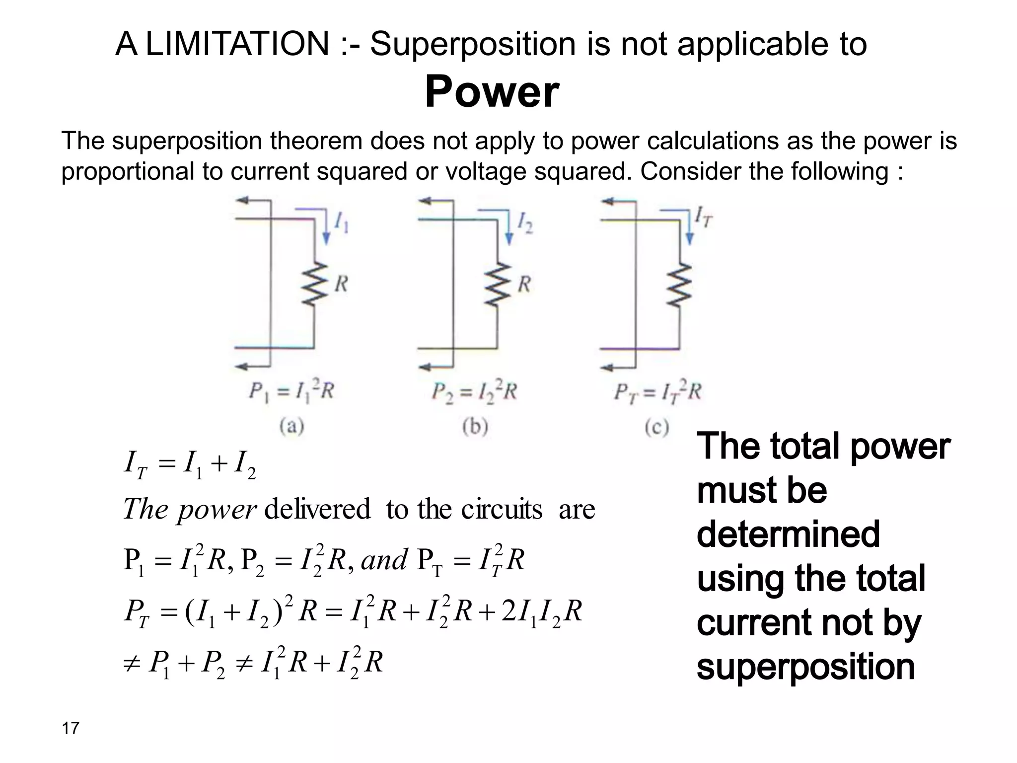


The superposition theorem allows the analysis of circuits with multiple sources by considering each source independently and adding their effects. It can be applied when circuit elements are linear and bilateral. To use it, all ideal voltage sources except one are short circuited and all ideal current sources except one are open circuited. Dependent sources are left intact. This allows the circuit to be solved for each source individually and the results combined through superposition. Examples demonstrate finding currents through specific elements in circuits with multiple independent and dependent sources. A limitation is that superposition cannot be used to determine total power due to power being related to current squared.