IRJET- Non Linear Static Seismic Analysis of Vertically Irregular Building Frames with Different Outrigger System
•
0 likes•9 views

This document discusses the use of outrigger systems to reduce lateral displacement in tall buildings subjected to earthquake loads. It analyzes three 30-story building models - a regular building, and buildings with vertical irregularities on one and both sides - with and without conventional and virtual outrigger systems. Results show that outrigger systems increase building stiffness and effectively reduce storey displacement. Optimal outrigger locations provide the maximum reduction in displacement. Conventional outriggers with X-bracing perform better than virtual outriggers. Outrigger systems improve a building's ability to resist lateral loads from earthquakes.

Recommended
Recommended
More Related Content
What's hot
What's hot (20)
Similar to IRJET- Non Linear Static Seismic Analysis of Vertically Irregular Building Frames with Different Outrigger System
Similar to IRJET- Non Linear Static Seismic Analysis of Vertically Irregular Building Frames with Different Outrigger System (20)
More from IRJET Journal
More from IRJET Journal (20)
Recently uploaded
Recently uploaded (20)
IRJET- Non Linear Static Seismic Analysis of Vertically Irregular Building Frames with Different Outrigger System
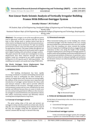
- 1. International Research Journal of Engineering and Technology (IRJET) e-ISSN: 2395-0056 Volume: 06 Issue: 06 | June 2019 www.irjet.net p-ISSN: 2395-0072 © 2019, IRJET | Impact Factor value: 7.211 | ISO 9001:2008 Certified Journal | Page 1812 Non Linear Static Seismic Analysis of Vertically Irregular Building Frames With Different Outrigger System Aswathy S Kumar1, M.V.Varkey2 1PG Student, Dept. of Civil Engineering, Amaljyothi College of Engineering and Technology, Kanjirappally. Kerala, India 2Assistant Professor Dept. of Civil Engineering, Amaljyothi College of Engineering and Technology, Kanjirappally. Kerala, India ---------------------------------------------------------------------***---------------------------------------------------------------------- Abstract - The outrigger is one of the most efficient system used to effectively control the excessive drift due to lateral load, so that, during small or medium lateral load due to either wind or earthquake load, the risk of structuraland non- structural damage can be minimized. For high rise building particularly in seismic active zonethissystemcanbechosenas an appropriate structure. This paper studies the efficient use of outrigger systems subjected to earth quake load in regular and irregular building with and without outrigger systems. . This paper presents the results of an investigation on storey displacement, base shear reduction through time history analysis. Loads are considered as per Indian standards IS: 875(part1), IS: 875 (part3) and IS: 1893 (part1)2016. The modelling and analysis were performed using ETABS 2015. Key Words: Outrigger, Storey displacement, Time History analysis, Bracing system, Earthquake. 1. INTRODUCTION Tall building development has been rapidly increasing worldwide. In modern tall building lateral loads induced by wind or earthquake are often resisted by a system of coupled shear walls. But when increasing height, the stiffness of the structure becomes more important and introduction of outrigger system between the shear walls and external columns is often used to provide sufficient lateral stiffness to the structure. Outrigger system are one such prominent system and are now considered to be most popular and efficient because they are easier to build, save on costs and provide good lateral stiffness to the structure. As outrigger is connected betweencoreand exteriorcolumn, this reduce overturning moment and efficiently reduces resulting lateral displacement at top floors. 1.1 Concept of outrigger system The great sailing ships of the past and present use outriggers to help resist the windforcesintheirsails.Likethe ship, the core in the tall building can be related to the mast of the ship, the outrigger acting like the spreaders and the exterior columns like the stays or shroud of the ship 1.2 Structural concepts When horizontal loading acts on the building, the column restrained outrigger resist the rotation of the core, causing the lateral deflections and moments in the core to be smaller than if the free standing core alone resisted the loading. Vertical irregularity in buildingsintroducesstaggeredabrupt reductions in floor area along the height of the building. Irregular building form is becoming increasingly popular in modern multi-storeybuildingconstructionmainlybecauseof its functional and aesthetic architecture. In particular, such a setback form provides for adequate daylight and ventilation for the lower storey in an urban locality with closely spaced tall buildings. Fig- 1: Structural Concept 2. TYPES OF OUTRIGGER SYSTEM On the basis of connectivity to the core there are two types of outrigger truss; Conventional Outrigger system Virtual Outrigger system 2.1 Conventional outrigger system In the conventional outrigger system, the outrigger trusses or girders are connected directly to shear walls or
- 2. International Research Journal of Engineering and Technology (IRJET) e-ISSN: 2395-0056 Volume: 06 Issue: 06 | June 2019 www.irjet.net p-ISSN: 2395-0072 © 2019, IRJET | Impact Factor value: 7.211 | ISO 9001:2008 Certified Journal | Page 1813 braced frames at the core and to columns located outboard of the core. Generally but not necessarily, the columns are at the outer edges of the building. The number of outriggers over the height of the building can vary from one to three or more. The outrigger trusses, which areconnectedtothecore and to columns outboard of the core, restrain rotation of the core and convert part of the moment in the core into a vertical couple at the columns. Shortening and elongation of the columns and deformation of the trusses will allow some rotation of the core at the outrigger. In most designs, the rotation is small enough that the core undergoes reverse curvature below the outrigger. Fig- 2: Conventional Outrigger System 2.2 Virtual outrigger system In the conventional outrigger system, outrigger trusses connected directly to the core and to outboard columns convert the “virtual” outrigger concept, the same transfer of overturning moment from the core to elements outboard of the core is achieved, but without a direct connection between the outrigger trusses and the core. The elimination of a direct connection between the trusses and the core avoids many of the problems associated with the use of outriggers. The basic concept behind the virtual outrigger is to use floor diaphragms, whicharetypicallyvery stiff and strong in their own plane, to transfer momentin the form of a horizontal couple from the core to trusses or walls that are not connected directly to the core. The trusses or walls then convert the horizontal couples into vertical couples in columns or other structural elements outboard of the core. Belt trusses and basement walls are well suited to use as virtual outriggers. Fig- 3: Virtual Outrigger System 2.3 Advantages of Outrigger System All exterior column participate in resisting overturning moment. Core overturning moment can be reduced through the reverse moment applied to the core at each outrigger connection. Exterior framing can consist of simple beam and column framing without the need for rigid frame type connection, thus reducing the overall cost. Reduction or elimination of uplift and net tension forces without the column and foundation system. There are no trusses in the space between the core and the building. 3. DETAILS OF MODEL The models which have been adopted for study are 3 models (normal 30 storey, irregularity at one side and irregularity at both side) all models are 30 storey (G+30). The building consist of rectangular columns with dimension 600mmx500mm, all beams with dimension 400mmx300mm.The height of each storeyis 3m and grade of concrete have been taken as M25. ETABS 2015 was used for modelling and analysisresult. Unit weight of brick = 20KN/m3 Thickness of slab = 100mm Thickness of shear wall = 200mm Live load on floor = 2KN/m2 Three models have been considered for study purpose
- 3. International Research Journal of Engineering and Technology (IRJET) e-ISSN: 2395-0056 Volume: 06 Issue: 06 | June 2019 www.irjet.net p-ISSN: 2395-0072 © 2019, IRJET | Impact Factor value: 7.211 | ISO 9001:2008 Certified Journal | Page 1814 1. Model A – Normal 30 storey building 2. Model B- – irregular building with irregularity at one side 3. Model C - irregular building with irregularity at both side 3.1 Building Data Table -1: Building description No of storey 30 Total height 3m Seismic zone IV Beam size 400mmx300mm Column size 600mmx500mm Bay in x and y direction 7 each 3m Response reduction factor 5 Importance factor 1 Support fixed Grade of Concrete M25 Seismic zone factor 0.24 Seismic intensity severe 3.2 Building model Fig -4: Beam column layout The analysis was carried out by considering the30storey RC building with concrete shear core and steel bracing in outrigger system in the building. In this concept, the outrigger connecting core to external column. In this study different types of bracing systems where used and three different position are selected for bracing system. 3.3 Conventional Outrigger System Fig- 5: 30 Storey building with outrigger system Fig- 6: 30 Storey building with irregularity at one side with outrigger system Fig- 7: 30 Storey building with irregularity at both side side with outrigger system
- 4. International Research Journal of Engineering and Technology (IRJET) e-ISSN: 2395-0056 Volume: 06 Issue: 06 | June 2019 www.irjet.net p-ISSN: 2395-0072 © 2019, IRJET | Impact Factor value: 7.211 | ISO 9001:2008 Certified Journal | Page 1815 3.4 Virtual Outrigger System Fig- 8: 30 Storey building with outrigger system Fig- 9: 30 Storey building with irregularity at one side with outrigger system Fig- 10: 30 Storey building with irregularity at both side side with outrigger system 4.RESULTS Chart- 1: variation in storey displacement for conventional outrigger in three models at different position Chart- 2: variation in storey displacement for virtual outrigger in three models at different position 4. CONCLUSIONS 1) The location of outrigger beam has critical influence on the lateral behavior of structure under earthquake load. 2) The optimum location with outrigger system is providing at top, 3/4th height, middle and at 1/4th height shows the maximum reduction in lateral deflection in the three models 3) Comparing the virtual outrigger system with conventional outrigger, conventional outrigger with x bracing gives good result.
- 5. International Research Journal of Engineering and Technology (IRJET) e-ISSN: 2395-0056 Volume: 06 Issue: 06 | June 2019 www.irjet.net p-ISSN: 2395-0072 © 2019, IRJET | Impact Factor value: 7.211 | ISO 9001:2008 Certified Journal | Page 1816 4) Using outrigger system in building it increase the stiffness and strength of the building and also resist lateral loadcausesduetoearthquake load. ACKNOWLEDGEMENT I express my heartfelt and sincere gratitude to GodAlmighty for the successful completion of my project without any disruption and I am thankful to my guide Asst. professor, M.V.Varkey in Civil Engineering Department for his encouragement and able guidance. REFERENCES [1] Chintanapakdee, C. and Chopra, A.K. “Seismic Response of Vertically Irregular Frames: Response History and Modal Pushover Analyses”, Journal of Structural Engineering, ASCE, Vol. 130, No. 8, pp. 1177-1185, 2004. [2] Raj Kiran Nanduri, and Ithesham Hussain “Optimum position of outrigger system for high rise reinforced concrete building under wind and earthquake load”, American Journal of engineering Research,2013. [3] S. Fawzia and T. Fatima Deflection control in composite building by using belt truss and outrigger system,world AcademF56y of Science, Engineering & Technology, vol 4, 2014. [4] Wood S. L., “Seismic Response of RC frames with irregular profiles”, Journal of Structural Engineering, ASCE, 118(2), 545-566, 2013. [5] Sarkar and Chopra“Period formulas for moment resisting frame buildings”. J Struct Eng, ASCE 123(11), pp. 1454-61, 2011.