This document compares the structural performance of a 20-story building designed with a diagrid system versus a simple frame system. Analysis shows the diagrid building experiences less top displacement, inter-story drift, and shear forces under wind and earthquake loads. Material consumption is also lower for the diagrid building, with 13% less concrete usage and 58% less steel. The diagrid system allows for more efficient lateral load resistance through axial forces in the diagonal members, compared to moment frames where columns must resist shear through bending.
Comparison of symmetric and asymmetric steel diagrid structures by non linear...eSAT Journals
Abstract Diagonalized grid structures – “diagrids” - have emerged as one of the most innovative and adaptable approaches to structuring buildings in this millennium. Diagrid is a particular form of space truss, it consists of perimeter grid made up of a series of triangulated truss system. Diagrid is formed by intersecting the diagonal and horizontal components. Construction of multi‐storey building is rapidly increasing throughout the world. Advance in construction technology, materials, structural systems, various analysis and design software have facilitated the growth of various kinds of buildings. Diagrid buildings are emerging as structurally efficient as well as architecturally and aesthetically significant assemblies for tall buildings. Recently these diagrid structural systems have been widely used for tall buildings due to the structural efficiency and aesthetic potential provided by the unique geometric configuration of the system. This paper presents a 12 storey steel diagrid structure which is 36m in height. Symmetric and asymmetric structural configurations of diagrid structures were modelled and analyzed using SAP 2000 by considering Dead load, Live load and Seismic Loads (IS 1893-Part-1, 2002). Then FEMA 356 hinges (auto hinges) are assigned to the same structure and Nonlinear Static (Pushover) analysis is carried out by using seismic load as the pushover load case to find out the performance points that is Immediate Occupancy, Life Safety, and Collapse Prevention of diagrid elements using static pushover curve. At the same time spectral displacement demand & spectral displacement capacity as well as spectral acceleration demand and spectral acceleration capacity is compared to know the adequacy of the design by using ATC capacity spectrum method. Keywords: Diagrid, Pushover analysis, Spectral displacement demand, Spectral displacement capacity, Spectral acceleration demand, Spectral acceleration capacity
Design study of stressed mirror polishing (smp) fixtureeSAT Journals
Abstract
Stressed Mirror Polishing (SMP) is a technique developed for the fabrication of off-axis aspheric mirror segments in a rapid and
cost effective manner. In SMP, the polishing of the mirror is carried out along with specific loads which are capable of deforming
a spherical mirror into any desired aspherical shape and thus reducing the difficulty of aspheric mirror polishing. When the blank
is removed from SMP after spherical polish and metrology, the blank will relax to the required aspherical surface with-in desired
PV & RMS surface figure accuracies. This paper discusses the different FEM approaches that can be adopted for simulating the
deformations in the mirror blank. For preliminary study purpose, a 36-cm diameter off-axis, meniscus shaped parabolic roundel
and a Spherical roundel mirror blanks are taken and required deformations are achieved through various FEM approaches. The
net deformed surface is validated and compared with a best fit near spherical surface. Additionally the reversibility of the
technique is also proved with-in required Surface accuracies. It is felt necessary that these preliminary simulations should form
the basis in understanding the warping process and their locations, so that full SMP fixture can be designed which is capable of
warping the mirrors.
Keywords: Stressed Mirror Polishing, Segmented Primary Mirror, Aspheric Segment Fabrication, Bending Fixture
Parametric study on slender column for flat plate structureeSAT Journals
Abstract This paper deals with effect of slender column on flat plate structure. The column is called slender if the height of is increased for functional purpose. The study is conducted on 18 flat-plate reinforced cement concrete (RCC) structural models. Among these18 models, 54 columns at three different locations (i.e. corner, edge and inner columns) are chosen for study. The models are developed using ETABS Software. Parametric study is performed by considering six different height of column ranging from 3048 mm to 6858 mm, using an increment of 762 mm along with three slab panels of size 4572 mm x 4572 mm, 6096 mm x6096 mm and 7620 mm x 7620 mm with five panels in both ways, considering both gravity and environmental load. The effect of slenderness ratio on load carrying capacity, design load and steel ratio is considered along with this the effect of additional moment due to slender compression member is also taken into account. It is observed that, columns in flat-plate structures are generally very sensitive if they are slender. It is observed that as the column length increases from 5502 mm and further, the steel ratio suddenly increases and it exceeds maximum allowed. As slenderness ratio increases, ratio of design load to the critical buckling load increases. Also resulting in increase of additional moment, decreasing load carrying capacity of column. This forces the design engineer to study effect of different parameter of the structure while designing high rise flat plate structure. Keywords: Flat Plate Structure, ETABS, Slenderness, Environmental load, design load and buckling load.
Effects of longer span floor system in the constancy of the multistoried stru...eSAT Journals
Abstract The main objective of this study is to investigate the structural integrity, stability and their comparison due to the effects of longer span floor systems considering some constancy in the multi-storied commercial and residential mixed-used structures. In recent times, mixed-use developments and buildings have created an up surging demand in perspective of relatively small area of lands like Bangladesh. But, the commercial developments consisting of underground basement required maximize serviceable column free open-floor spaces for more flexibility, marketability and uninterrupted executive car parking of the end-users. Now, the column free open-plan floor spaces, usually ranges from 18~27 ft, even up to 45 ft. or more [5], offers a bulky change in span length of the slab that results the longer span structure. Again, the longer span structure is directly related with the beam length which promptly affects the thickness of the slab as well as the sizes of beams, columns and the foundations. In this study, two different span lengths of the mixed-use structural Models are considered based on the economical range [18ft-30ft] of the RC floor systems. Then, both of the structural Models are compared based on the following parameters: design aspects, reduction in the number of components, sizes & thickness, weight of steel and volume of concrete. It is found that, longer span structure keeps highest effects on the RC columns and increase in size by 104.3%. This study will also be helpful for a designer to select an appropriate size of the structural components within the economical ranges of these types of particular RC structures in future Keywords: Regular Span Structure, Longer Span Structure, Flat Plate Slab, Flat Slab, Edge Supported Slab Andmat Foundation.
Optimization of a multistorey building by optimum positioning of shear walleSAT Journals
Abstract The shear wall is a structural element which is used to resist earthquake forces. These wall will consumptives shear forces & will prevent changing location-position of construction & consequently destruction. On other hand, shear wall arrangement must be absolutely accurate, if not, we will find negative effect instead. For example if the shear walls make an increase distance between mass centre and hardness centre, we cannot expect a good tensional behavior from the structure. In case of mass centre and hardness centre coincide with each other, at that time the distance of shear wall from the mass centre also plays an important role in the shear contribution of the shear wall. The bending moment, shear force, torsion, axial force contribution by rest of the structural element and the ultimate design of all the structural components also affected by that. A study has been carried out to determine the optimum Structural configuration of a multistory building by changing the shear wall locations radically. Four different cases of shear wall position for a 10 storey residential building with keeping zero eccentricity between mass centre and hardness centre have been analyzed and designed as a space frame system by computer application software, subjected to lateral and gravity loading in accordance with IS provisions. Keywords: Shear walls, Lateral loading, Zero eccentricity, Stresses, Design configuration.
IJRET : International Journal of Research in Engineering and Technology is an international peer reviewed, online journal published by eSAT Publishing House for the enhancement of research in various disciplines of Engineering and Technology. The aim and scope of the journal is to provide an academic medium and an important reference for the advancement and dissemination of research results that support high-level learning, teaching and research in the fields of Engineering and Technology. We bring together Scientists, Academician, Field Engineers, Scholars and Students of related fields of Engineering and Technology
Effect of variation of plastic hinge length on the results of non linear anal...eSAT Journals
Abstract The nonlinear Static procedure also well known as pushover analysis is method where in monotonically increasing loads are applied to the structure till the structure is unable to resist any further load. It is a popular tool for seismic performance evaluation of existing and new structures. In literature lot of research has been carried out on conventional pushover analysis and after knowing deficiency efforts have been made to improve it. But actual test results to verify the analytically obtained pushover results are rarely available. It has been found that some amount of variation is always expected to exist in seismic demand prediction of pushover analysis. Initial study is carried out by considering user defined hinge properties and default hinge length. Attempt is being made to assess the variation of pushover analysis results by considering user defined hinge properties and various hinge length formulations available in literature and results compared with experimentally obtained results based on test carried out on a G+2 storied RCC framed structure. For the present study two geometric models viz bare frame and rigid frame model is considered and it is found that the results of pushover analysis are very sensitive to geometric model and hinge length adopted. Keywords: Pushover analysis, Base shear, Displacement, hinge length, moment curvature analysis
A study on plastic hinge formation in rc frame by nonlinear static analysiseSAT Journals
Abstract The design of effective structural system configured with all seismic performance objectives ranging from serviceability considerations to life safety and collapse prevention is the most important part of Seismic design. For seismic performance evaluation of structures, the static push over analysis which provides adequate information on seismic demands imposed by the ground motion has been popularized in recent decades. This evaluates the expected performance of a structure by estimating its strength and deformation demands to design ground motions by means of static inelastic analysis. The evaluation considers the factors such as global drift, interstorey drift, inelastic element deformations, deformation between elements etc. The first and most important step of this procedure, modeling of the structure demands the determination of the nonlinear properties of each component that are quantified by strength and deformation capacities. The factors that affect the ultimate deformation capacity of a structure also depends on the ultimate curvature and plastic hinge properties. The effect of plastic hinge properties in nonlinear analysis has been studied by many researchers. However, a little or negligible attention has given to understand the sequence of hinge formation and its effect. An attempt has been made in this paper to understand the order of hinge formation for ground motions and thereby tried to enhance the accuracy of push over analysis. A single bay single storied RC frame has been analyzed by using the software package SAP 2000 and hinges formed were observed with their order and location and results have been discussed.
Keywords: Push over Analysis, interstorey drift, Plastic hinge, nonlinear properties and SAP 2000.
IJRET : International Journal of Research in Engineering and Technology is an international peer reviewed, online journal published by eSAT Publishing House for the enhancement of research in various disciplines of Engineering and Technology. The aim and scope of the journal is to provide an academic medium and an important reference for the advancement and dissemination of research results that support high-level learning, teaching and research in the fields of Engineering and Technology. We bring together Scientists, Academician, Field Engineers, Scholars and Students of related fields of Engineering and Technology
Optimization of prestressed concrete girdereSAT Journals
Abstract Bridge construction today has achieved a worldwide level of importance. Bridges are the key elements in any road network Use of prestressed concrete I girder bridge is gaining popularity in bridge engineering fraternity because of its better stability, serviceability, economy, aesthetic appearance and structural efficiency. This paper concerned idea about prestressed concrete.In the method of prestressing two types are consider that pre tensioning and post tensioning .At the time of prestressing different losses are consider. These are the losses due to elastic shortening, friction losses, relaxation losses, losses due to creep and shrinkage. In this way total amount of losses in pretensioning and post tensioning calculate and detailed information has given in this report. The objective is to minimize the total cost in the design process of the bridge system considering the cost of materials like steel, concrete, tendons etc. For a particular problem the design variables considered for the cost minimization of the bridge system, are depth of girder, various cross sectional dimensions of the girder, number of tendons, A programme is developed for analysis and designing an low cost prestressed girder in MATLAB R2010a software. The optimtool is used to find out minimum cost of structure Illustrative case of prestressed girder presented and discuss by using active set method from optimtool. Optimization problem is characterized by considering design variables and bound constraints are according to AASHTOO Standards ,IRC 21-2000 bridge specifications .The proposed cost optimization approach is compared with an existing project which leads to a considerable cost saving while resulting in feasible design. Keywords: Post tension I girder, Conventional design, Optimal design, MATLAB Software etc…
Design of waste heat driven vapour adsorption cooling system for vehicle air ...eSAT Journals
Abstract In this present era more & more focus is to be given on energy conservation. Refrigeration & air conditioning is one of the growing field of engineering, the existing system are hampering the environment as they are suffering from various environmental problems such as depletion of ozone layer & global warming due to emission of harmful gases such as HFC’s ,CFC’s & CO2 as they were using traditional refrigerants. Waste heat driven Vapour adsorption cooling system is eco-friendly, efficient, & reliable in nature. But on the other hand this system having lowers COP as compare to existing systems which is Due to the lack of research and advancement in the system. By considering the environmental aspects & need of energy conservation it is necessary to design and developed the VAR’s system which will successfully compete the existing systems. This paper will give the idea about the Design of waste heat driven vapour adsorption system of 2KW capacity for vehicle air-conditioning & refrigeration application. The adsorber bed is the heart of the cooling system and it can affect the performance of the system to the greater extent. So that while designing the VAR cooling system more focused is given on design and selection of adsorber bed. This article mainly focused on the various and important design parameters of the vapour adsorption cooling system Such as Adsorber bed design, adsorber and adsorbate mass, design of evaporator & condenser, Coefficient of performance(COP), Specific cooling power (SCP) and the other performance affecting parameters. Keywords: Vapour Adsorption, Design Parameters, Low Grade Thermal Energy, Adsorbate & Adsorbent.
Study on laminated rubber bearing base isolators for seismic protection of st...eSAT Journals
Abstract
Base isolation or seismic base isolation is an effective means for protection of structures, its contents and its occupants during the event of an earthquake. The principle of base isolation is vibration isolation. It decouples the building from damaging action of the earthquake. The isolator partially reflects and partially absorbs input seismic energy before it gets transmitted to the superstructure. Laminated Rubber Bearing Isolators are placed between the superstructure and foundation, which reduces the horizontal stiffness of the system. It thereby increases the time period of the structure and decreases the spectral acceleration of the structure. The superstructure acts like a rigid body, thus inter storey drift is reduced. Such type of isolators are used in practice in India, yet a proper design procedure based on IS code is unavailable. The paper presents design procedure for LRB adopting the procedure of IS 1893:2002 (Part-1) for earthquake resistant design of buildings. Design charts have been developed and presented in this paper which gives isolator diameter and rubber thickness as design outputs. The design procedure requires different input parameters like fundamental period and damping of the fixed base structure, axial load on the column, seismic zone, type of soil and shore hardness of rubber. These design charts enable the designer to easily arrive at the isolator parameters to achieve seismic isolation. Using the charts, case study has been done using SAP2000. Building displacement and acceleration are compared for model with and without base isolator. Comparative study of linear and non-linear base isolators has also been carried out. Linear and non-linear time history analysis has been done using El Centro earthquake.
Keywords: base isolation, laminated rubber bearing, IS Code, seismic protection, design charts, time history analysis, SAP2000
Comparison of bracings and shear walls as seismic strengthening methods to bu...eSAT Publishing House
IJRET : International Journal of Research in Engineering and Technology is an international peer reviewed, online journal published by eSAT Publishing House for the enhancement of research in various disciplines of Engineering and Technology. The aim and scope of the journal is to provide an academic medium and an important reference for the advancement and dissemination of research results that support high-level learning, teaching and research in the fields of Engineering and Technology. We bring together Scientists, Academician, Field Engineers, Scholars and Students of related fields of Engineering and Technology.
Parametric Study on Diagrid Structural System with and without Shear WallsAI Publications
Among the various lateral load resisting systems of the tall structures, diagrid structural system is a unique structural system and found effective compared to other bracing systems, which is increasingly popular from the past decades. The diagrids are perimeter structural configurations characterized by a grid of diagonal members which are involved both in gravity and in lateral load resistance. The diagrid structure ensures the overall stiffness and strength of the building only engaging the diagonal members in a purely axial behaviour and fully braces the interior gravity columns for stability only at joints of diagrid. The intermediate floors, are not laterally restrained by the global behaviour of the diagrid system, means if diagonals are continuous throughout the module height, the floors would derive a certain degree of lateral stiffness only from the flexural stiffness of the diagrids. Although diagrid system is good enough to perform well in lateral load resisting compare to other simple frame and shear wall building, we can combined the diagrid structure with shear walls for optimum design. The present study aimed to understand the behaviour of the diagrid structural system with shear walls at core. For this study a regular square plan of 30m × 30m diagrid structure considering different storey module (i.e. 4, 6, 8 & 12) with and without core Shear Walls is modelled and analyzed. For minimum displacement and drift different plan shape of shear wall are taken and one of them with optimum results is used for further analysis. Then behaviour of diagrid structure with and without shear wall along the height is also studied considering 24, 36 and 48 storey. ETABS software is used for modelling and analysis. Parameters such as inter storey drift-ratio, storey displacement, base shear and reduction in lateral load on diagrid are taken into consideration.
How to up Optimize Your Google Product Feed in Time for Black FridayTinuiti
In this 60-minute feed management course, CPC Strategy’s Jason Bell will dive into the top enhancements you need to be making for Black Friday / Cyber Monday.
Esta apresentação tem por finalidade fornecer informações básicas sobre a administração de um ambiente IBM Connections. Falando um pouco sobre customização e administração.
Analysis of diagrid structure in comparison with exterior braced frame structureeSAT Journals
Abstract
Over the last 10 years, diagrid structures have proven to be highly adaptable in structuring a wide range of building types, spans
and forms. In most applications, diagrids provide structural support to buildings that are non rectilinear, adapting well to highly
angular buildings and curved forms. The origin of the diagrid structural technology lies at the crossroads of engineering and
architecture. The term “diagrid” have come from perimeter diagonals which have good structural efficiency and is gaining new
interests in designing of tall structures because of its lattice like look. The term “diagrid” is a blending of the words “diagonal”
and “grid” and refers to a structural system that gains its structural integrity through use of triangulation. In the diagrid
structures, the vertical columns from the periphery are eliminated and this constructs the main difference between diagrids and
exterior braced frames. Having triangulated configuration, the diagrids are able to carry the gravity and lateral loads. They also
effectively minimize shear deformation as the diagonals carry the loads axially. The diagrid structural system is adopted these
days for tall buildings because of its stiffness and flexibility in the architectural planning. This paper presents the study of 20-
storey diagrid structure in comparison with exterior braced frame structure.Analysis results and design of both the models are
presented in terms of storey shear, displacement, drift and summary of lateral and gravity forces.
KeyWords:Diagrid structure, Exterior braced frame structure, Storey displacement, and Storey drift
Seismic evelution of rc space frame with rectangular and equivalent square co...eSAT Publishing House
IJRET : International Journal of Research in Engineering and Technology is an international peer reviewed, online journal published by eSAT Publishing House for the enhancement of research in various disciplines of Engineering and Technology. The aim and scope of the journal is to provide an academic medium and an important reference for the advancement and dissemination of research results that support high-level learning, teaching and research in the fields of Engineering and Technology. We bring together Scientists, Academician, Field Engineers, Scholars and Students of related fields of Engineering and Technology
ISEISMIC PERFORMANCE OF RC FRAMED BUILDINGS UNDER LINEAR DYNAMIC ANALYSISjcie...IAEME Publication
The construction of multi-storey buildings is increasing constantly all over the world. The
development of highly advanced structural system is mainly based on the quality of aesthetic
expression, structural efficiency, and geometric versatility. The selected structural system should be
such that it has to be effectively utilized for structural requirements. The unique geometrical
configuration of the diagrid structural systems have driven them to be used for high rise buildings
providing the structural efficiency and aesthetic potential. In this present work, four different
models of I section of a 30 storey RC Frame building with plan size 18 m × 18 m located in seismic
zone V have been considered for analysis. Steel diagrid structure of 2 storey and 6 storey models
and Infill wall model are analyzed and compared with conventional RC Frame model and is
studied using linear dynamic analysis. ETabs software is used for modeling and analysis of
structural members. Comparison of analysis results in terms of storey Displacement, Drift, Bending
Moment, Axial forces, Time period, Base shear is presented and the results obtained were
compared with those obtained from other models.
IRJET- Analysis of an Irregular Building with Stiffened Steel Plate Shear...
IJRET20140304067
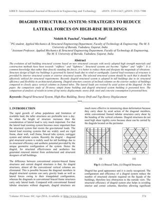
1. IJRET: International Journal of Research in Engineering and Technology eISSN: 2319-1163 | pISSN: 2321-7308
__________________________________________________________________________________________
Volume: 03 Issue: 04 | Apr-2014, Available @ http://www.ijret.org 374
DIAGRID STRUCTURAL SYSTEM: STRATEGIES TO REDUCE
LATERAL FORCES ON HIGH-RISE BUILDINGS
Nishith B. Panchal1
, Vinubhai R. Patel2
1
PG student, Applied Mechanics & Structural Engineering Department, Faculty of Technology & Engineering, The M. S.
University of Baroda, Vadodara, Gujarat, India
2
Assistant Professor, Applied Mechanics & Structural Engineering Department, Faculty of Technology & Engineering,
The M. S. University of Baroda, Vadodara, Gujarat, India
Abstract
The evolution of tall building structural systems based on new structural concepts with newly adopted high strength materials and
construction methods have been towards “stiffness” and “lightness”. Structural systems are become “lighter” and “stiffer”. It is
common knowledge that rather than directly standing the forces, it is better to reduce them and dissipate the magnitude of vibrations.
Structure design of high rise buildings is governed by lateral loads due to wind or earthquake. Lateral load resistance of structure is
provided by interior structural system or exterior structural system. The selected structural system should be such that it should be
effectively utilized for structural requirements. Recently diagrid structural system is adopted in tall buildings due to its structural
efficiency and flexibility in architectural planning. Diagrid structure consists of inclined columns on the exterior surface of buildings
compared to closely space vertical columns in framed tubes. The lateral loads are resisted by axial action of the diagonal. In this
paper, the comparison study of 20-storey simple frame building and diagrid structural system building is presented here. The
comparison of analysis of results in terms of top storey displacement, storey drift, steel and concrete consumption is presented here.
Keywords: Diagrid Structural System, High-Rise Building, Storey Drift and Top-Storey Displacement
-----------------------------------------------------------------------***-----------------------------------------------------------------------
1. INTRODUCTION
The rapid growth of urban population and limitation of
available land, the taller structures are preferable now a day.
So when the height of structure increases then the
consideration of lateral load is very much important. For that
the lateral load resisting system becomes more important than
the structural system that resists the gravitational loads. The
lateral load resisting systems that are widely used are rigid
frame, shear wall, wall frame, braced tube system, outrigger
system and tubular system. Recently the diagrid – diagonal
grid structural system is widely used for tall buildings due to
its structural efficiency and aesthetic potential provided by the
unique geometric configuration of the system. Hence the
diagrid, for structural effectiveness and aesthetics has
generated renewed interest from architectural and structural
designers of tall buildings.
The difference between conventional exterior-braced frame
structures and current diagrid structures is that, for diagrid
structures, almost all the conventional vertical columns are
eliminated. This is possible because the diagonal members in
diagrid structural systems can carry gravity loads as well as
lateral forces owing to their triangulated configuration,
whereas the diagonals in conventional braced frame structures
carry only lateral loads. Compared with conventional framed
tubular structures without diagonals, diagrid structures are
much more effective in minimizing shear deformation because
they carry shear by axial action of the diagonal members,
while conventional framed tubular structures carry shear by
the bending of the vertical columns. Diagrid structures do not
need high shear rigidity cores because shear can be carried by
the diagrids located on the perimeter.
(i) (ii)
Fig-1: (i) Braced Tube, (ii) Diagrid Structure
Diagrid has good appearance and it is easily recognized. The
configuration and efficiency of a diagrid system reduce the
number of structural element required on the façade of the
buildings, therefore less obstruction to the outside view. The
structural efficiency of diagrid system also helps in avoiding
interior and corner columns, therefore allowing significant
2. IJRET: International Journal of Research in Engineering and Technology eISSN: 2319-1163 | pISSN: 2321-7308
__________________________________________________________________________________________
Volume: 03 Issue: 04 | Apr-2014, Available @ http://www.ijret.org 375
flexibility with the floor plan. Perimeter “diagrid” system
saves approximately 20 percent structural steel weight when
compared to a conventional moment-frame structure.
An early example of the diagrid structure is the IBM Building
in Pittsburgh built in the early 1960s, with its 13-storey
building height. Another famous examples of diagrid structure
all around the world are the Swiss Re London, Hearst Tower
in New York, Capital Gate tower in Abu Dhabi, Cyclone
Tower in Asan (Korea) and new World Trade Centre in New
York.
(i) (ii) (iii)
Fig- 2: (i) Swiss Re London, (ii) IBM Building, (iii) Hearst
Tower
In this paper, a comparative study of 20-storey simple frame
building and with same configuration, a diagrid structural
system building is presented here. A simple floor plan of 18m
x 18m size is considered. ETABS 9.7.4 software is used for
modelling and analysis of structural members. The analysis is
carried out for 20-storey building with floor height 3.6m.
Comparison of analysis results in terms of top storey
displacement, inter storey drift, storey shear, steel and
concrete consumption is presented here.
2. ANALYSIS OF 20-STOREY BUILDING
2.1 Building Configuration
The 20-storey building is having 18m x 18m plan dimension
and 72m total height of building. The storey height is 3.6m.
The typical plan and elevation are shown in figure 3. There are
two models for comparative study, one is for simple frame
building and another is for diagrid structure. The building data
is kept same for both models. The beam size and column sizes
are as shown in table-1. The slab thickness is 120mm. The
diagonal member’s (Diagrid) size is 300mm x 300mm for
diagrid structure and it is at the angle of 78.2°. And for simple
frame building, the perimeter columns sizes are also 450mm x
450mm. The design dead load and live load on terrace level
are 5.6kN/m2 and 1.5kN/m2 respectively and for typical floor
slab is 4.6kN/m2 and 2kN/m2. The design earthquake load is
computed based on the zone factor 0.16, soil type II,
Importance factor 1, Response Reduction 5 as per IS-1893-
2002. The design wind load is computed based on location
Vadodara, Wind speed 44 m/s, Terrain category 2, Structure
class B, Risk Coefficient 1, Topography factor 1. Modelling,
analysis and design of diagrid structure are carried out using
ETABS 9.7.4 software. The end condition for diagrid is
assumed as hinged. The support conditions are assumed as
fixed. The design of member is carried out on the basis of IS-
456-2000.
(i)
(ii) (iii)
Fig- 3: (i) plan (ii) elevation of simple frame structure,
(iii) elevation of diagrid structure
3. IJRET: International Journal of Research in Engineering and Technology eISSN: 2319-1163 | pISSN: 2321-7308
__________________________________________________________________________________________
Volume: 03 Issue: 04 | Apr-2014, Available @ http://www.ijret.org 376
2.2 Analysis Results
The analysis results in terms of displacement, inter storey
drift, storey shear are presented here. The summary reaction of
Gravity loads, lateral loads due to earthquake and wind is
shown in table-2.
Table: - 1 Reaction
The displacement of 20-storey diagrid structure and simple
frame structure building is shown in fig-4. It is observed that
displacement in simple frame is higher compared to the
diagrid frame building in EQX, EQY, WLX and WLX case.
The inter storey drift of diagrid structure and simple frame
structure building is shown in fig-5. It is observed that inter
storey drift in simple frame building is higher compared to the
diagrid frame building EQX, EQY, WLX and WLX case. The
distribution of storey shear along the height of 20-storey
diagrid building and simple frame building is shown in fig-6.
It is observed that storey shear in simple frame building is
higher compared to the diagrid frame building EQX, EQY,
WLX and WLX case. All the results are as shown in table-2.
Table:-2 Displacement Results
CASE DIAGRID
STRUCT
URE
SIMPLE
FRAME
BUILDI
NG
PERMI
SSIBLE
VALU
ES
TOP
STOREY
DISPLAC
EMENT
EQX/EQ
Y
31.5 mm 78.3mm 144mm
WLX/WL
Y
53.9mm 132.3mm 144mm
STOREY
DRIFT
EQX/EQ
Y
0.264mm 0.483mm 14.4mm
WLX/WL
Y
0.353mm 0.542mm 14.4mm
Fig - 4 Storey Vs Displacement
Fig - 5 Storey Vs Storey Drift
Fig - 6 Storey Vs Storey Shear
LOADING (KN) TOTAL
REACTION
ON DIAGRID
STRUCTURE
TOTAL
REACTION
ON SIMPLE
FRAME
STRUCTURE
GRAVITY
LOAD(DL + LL)
84144.02 87600.17
EQ LOAD IN X-
DIR
905.13 931.07
EQ LOAD IN Y-
DIR
905.13 931.07
WIND LOAD IN X-
DIR
2310.11 2310.11
WIND LOAD IN Y-
DIR
2310.11 2310.11
4. IJRET: International Journal of Research in Engineering and Technology eISSN: 2319-1163 | pISSN: 2321-7308
__________________________________________________________________________________________
Volume: 03 Issue: 04 | Apr-2014, Available @ http://www.ijret.org 377
3. DESIGN OF 20-STOREY DIAGRID AND
SIMPLE FRAME BUILDING
The design of diagrid structure and simple frame building is
carried out using ETABS 9.7.4 software. The gravity load ,
earth quake load and wind load are assigned to both structure
with all load combinations. From the analysis results design of
beam, column and diagonal members is carried out as per IS:
456-2000. The compressive strength of concrete is 40 N/mm2
and for steel 415 N/mm2 is considered. The beam and column
sizes are preliminary decided for both the building. Then after
analysis the sizes are changed to prevent the failure and
excessive top storey displacement. So the final sizes of
members optimum sizes for both the buildings as shown in
table-3.
Table:-3 Member sizes for both models
3.1 Material Consumption
The consumption of concrete and steel is calculated for both
the building. It is observed that the consumption of material
for simple frame building is higher than the diagrid structure
building. The difference in the consumption of concrete for
both the building is 13.01% and for steel is 57.9% which is
shown in the figure-6.
Fig - 7 Quantity of Diagrid Structure and simple frame
structure
3. CONCLUSIONS
In this paper, comparative analysis and design of 20-storey
diagrid structural system building and simple frame building is
presented here. A regular floor plan of 18m x 18m size is
considered. ETABS 9.7.4 software is used for modelling and
analysis of structure. Analysis results like displacement, storey
drift, storey shear are presented here. Also design of both
structures is done and optimum member sizes are decided to
satisfy the code criteria.
We conclude from the study that,
As the lateral loads are resisted by diagonal columns, the
top storey displacement is very much less in diagrid
structure as compared to the simple frame building.
The storey drift and storey shear is very much less for
diagrid structural system.
Diagrid provide more resistance in the building which
makes system more effective.
The design of both structures are done by using same
member size but that member sizes are not satisfied to
design criteria in case of simple frame structure and
failure occurs with excessive top storey displacement. So
the higher sizes of members are selected to prevent the
failure criteria.
Diagrid structure system provides more economy in terms
of consumption of steel and concrete as compared to
simple frame building.
Diagrid structural system provides more flexibility in
planning interior space and façade of the building.
ACKNOWLEDGEMENTS
I am very much thankful to my guide Dr. Vinubhai R. Patel
for their guidance and also very much thankful to Applied
Mechanics Department & Structural Engineering Department,
Faculty of Technology & Engineering, The M. S. University
Of Baroda for giving such a good facilities and platform to
complete the dissertation work and also my dear friends who
have support me to complete this work.
REFERENCES
[1]. Kyoung S. Moon, Jerome J. Connor and John E.
Fernandez, “Diagrid Structural Systems for Tall Building:
Characteristics and Methodology For Preliminary Design”,
Willey Interscience Publication.
[2]. Khushbu Jani and Paresh V. Patel, “Analysis and Design
of Diagrid Structural System for High Rise Steel Buildings”,
Published by Elesevier Ltd.
[3]. Mir M. Ali and Kyoung S. Moon, “Structural
Developments in Tall Buildings: Current Trends and Future
Prospects”, Architectural Science Review Vol 50.3, pp 205-
223.
[4]. Kyoung S. Moon, “Diagrid Structures for Complex-
Shaped Tall Building”, Published by Elesevier Ltd.
MEMBER MEMBER
NOS.
DIAGRID
STRUCTURE
SIMPLE
FRAME
STRUCTURE
BEAM B1 230 mm x 500
mm
300 mm x 600
mm
B2 230 mm x 500
mm
230 mm x 500
mm
B3 230 mm x 450
mm
230 mm x 450
mm
COLUMN C1 700 mm x 700
mm
750 mm x 750
mm
DIAGRID D1 300 mm x 300
mm
450 mm x 450
mm
5. IJRET: International Journal of Research in Engineering and Technology eISSN: 2319-1163 | pISSN: 2321-7308
__________________________________________________________________________________________
Volume: 03 Issue: 04 | Apr-2014, Available @ http://www.ijret.org 378
[5]. J. Kim, Y.Jun and Y.-Ho Lee, “Seismic Performance
Evaluation of Diagrid System Buildings”, 2nd Specially
Conference on Disaster Mitigation, Manitoba.
[6]. Charnish B. and McDonnell T. “The Bow: Unique
Diagrid Structural System for a Sustainable Tall Building”,
CTBUH 8th World Congress, Dubai.
[7]. IS: 456-2000. Plain and Reinforced Concrete- Code of
Practice (Fourth Revision), Bureau of Indian Standard, New
Delhi.
[8]. IS: 1893(Part-I)-2002, Criteria for Earthquake Resistant
Design of Structures, Bureau of Indian Standard, New Delhi.
[9]. IS: 875(Part-I, II, III)-1987, Code of Practice for Design
Loads (other than Earthquake) for Buildings and Structures,
Bureau of Indian Standard, New Delhi.
BIOGRAPHIES
I am Nishith B. Panchal. I am pursuing my
Master Of Engineering study in Structural
engineering branch from The M. S. University
of Baroda. I am doing my dissertation work
under the guidance of Dr. V. R. Patel sir. I
have done my Bachelor of Engineering (civil
engg) study also from The M. S. University of Baroda.
Dr. Vinubhai R. Patel is an Assistant Professor
in Applied Mechanics and Structure
Engineering Department, Faculty Of
Technology & Engineering, The M. S.
University of Baroda. He is also a structure
designed consultant and approved valuer. He
has more than 15 years of experience in the field of structural
and civil engineering. He had designed more than 1500
projects which includes industrial, factory buildings and high-
rise buildings.