A study on behaviour of outrigger system on high rise steel structure by varying outrigger depth
•
6 likes•1,224 views

This study analyzed the behavior of an outrigger structural system on a 40-story steel structure by varying the depth of the outriggers. Three models were analyzed: with outrigger depth equal to full story height, 2/3 of story height, and 1/3 of story height. Lateral displacement and story drift were compared between a structure with a central braced core and each outrigger model. Results showed that providing additional outriggers and belt trusses reduced displacement and drift by up to 36.96% and 30.10% respectively. Reducing outrigger depth to 2/3 and 1/3 of story height resulted in only minor increases in displacement and drift compared to full height outriggers. The

Recommended
More Related Content
What's hot
What's hot (20)
Viewers also liked
Viewers also liked (20)
Similar to A study on behaviour of outrigger system on high rise steel structure by varying outrigger depth
Similar to A study on behaviour of outrigger system on high rise steel structure by varying outrigger depth (20)
More from eSAT Journals
More from eSAT Journals (20)
Recently uploaded
Recently uploaded (20)
A study on behaviour of outrigger system on high rise steel structure by varying outrigger depth
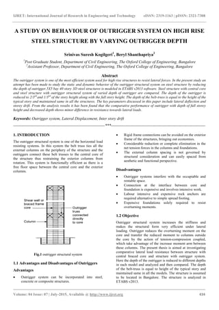
- 1. IJRET: International Journal of Research in Engineering and Technology eISSN: 2319-1163 | pISSN: 2321-7308 _______________________________________________________________________________________ Volume: 04 Issue: 07 | July-2015, Available @ http://www.ijret.org 434 A STUDY ON BEHAVIOUR OF OUTRIGGER SYSTEM ON HIGH RISE STEEL STRUCTURE BY VARYING OUTRIGGER DEPTH Srinivas Suresh Kogilgeri1 , Beryl Shanthapriya2 1 Post Graduate Student, Department of Civil Engineering, The Oxford College of Engineering, Bangalore 2 Assistant Professor, Department of Civil Engineering, The Oxford College of Engineering, Bangalore Abstract The outrigger system is one of the most efficient system used for high rise structures to resist lateral forces. In the present study an attempt has been made to study the static and dynamic behavior of the outrigger structural system on steel structure by reducing the depth of outrigger.5X5 bay 40 story 3D steel structures is modeled in ETABS v2013 software. Steel structure with central core and steel structure with outrigger structural system of varied depth of outrigger are compared. The depth of the outrigger is reduced to 2/3rd and 1/3rd of the story height along with the full story height. The depth of the belt-truss is equal to the height of the typical story and maintained same in all the structures. The key parameters discussed in this paper include lateral deflection and storey drift. From the analysis results it has been found that the comparative performance of outrigger with depth of full storey height and decreased depth shows minor difference in resistance towards lateral loads. Keywords: Outrigger system, Lateral Displacement, Inter story drift --------------------------------------------------------------------***---------------------------------------------------------------------- 1. INTRODUCTION The outrigger structural system is one of the horizontal load resisting systems. In this system the belt truss ties all the external columns on the periphery of the structure and the outriggers connect these belt trusses to the central core of the structure thus restraining the exterior columns from rotation. This system is functionally efficient as there is a free floor space between the central core and the exterior columns. Fig.1 outrigger structural system 1.1 Advantages and Disadvantages of Outriggers Advantages Outrigger system can be incorporated into steel, concrete or composite structures. Rigid frame connections can be avoided on the exterior frame of the structures, bringing out economies. Considerable reduction or complete elimination in the net tension forces in the columns and foundations. The external column spacing is not governed by structural consideration and can easily spaced from aesthetic and functional perspective. Disadvantages Outrigger systems interfere with the occupiable and rentable space. Connection at the interface between core and foundation is expensive and involves intensive work. Labour intensive and expensive rock anchors are required alternative to simple spread footing. Expensive foundations solely required to resist overturning moments. 1.2 Objective Outrigger structural system increases the stiffness and makes the structural form very efficient under lateral loading. Outrigger reduces the overturning moment on the core and transfer the reduced moment to columns outside the core by the action of tension-compression coupled, which take advantage of the increase moment arm between these columns. The present thesis is aimed at investigating comparative lateral load resistance between structure with central braced core and structure with outrigger system. Here the depth of the outrigger is reduced to different depths in each model and analyzed and then compared. The depth of the belt-truss is equal to height of the typical story and maintained same in all the models. The structure is assumed to be located in Bangalore. The structure is analyzed in ETABS v2013.
- 2. IJRET: International Journal of Research in Engineering and Technology eISSN: 2319-1163 | pISSN: 2321-7308 _______________________________________________________________________________________ Volume: 04 Issue: 07 | July-2015, Available @ http://www.ijret.org 435 2. MODELLING AND ANALYSIS The structure is assumed to be located at Bangalore. For analysis, 40 story steel structure is considered. The plan dimension of the structure is 30X30m. typical story height is 3.2m, overall structure height is 128m. The structure is symmetrical about both X & Y axis. Chevron (inverted v) bracings is used for both core and outrigger system. The structure is modeled as without infill. Material of concrete grade is M20. Slab thickness is 150mm. column size changes at each 10 story. Modal damping of 2% is considered. To enable diaphragm action, diaphragm is assigned at each level. The structure is assumed to be fixed at the ground level. The depth of the outrigger is reduced to 2/3rd and 1/3rd of the story height along with the full depth. The depth of the belt-truss is maintained same in all the structures i.e. height of typical story. The structure with braced core is compared with structures of varied depth of outrigger. Initially the structure with braced core is compared with the structure with cap truss only, then additional outrigger and belt truss is added at the 0.5H of the structure and then compared. Equivalent static method and Response spectrum method are used in the analysis as per IS-1893 (Part 1). The structure is subjected to wind load as per IS-875 (Part 3). 2.1 Details of Model Fig.2 Plan of structure Fig.3 Elevation of structure with core Fig.4 3D view of typical story with outrigger depth 1/3rd of story height
- 3. IJRET: International Journal of Research in Engineering and Technology eISSN: 2319-1163 | pISSN: 2321-7308 _______________________________________________________________________________________ Volume: 04 Issue: 07 | July-2015, Available @ http://www.ijret.org 436 Fig.5 Elevation of structure with outriggers 2.2 Material Properties Concrete: Grade M-20, Density 2458.538 Kg/m3, Young’s Modulus 22360.68 Mpa, Shear Modulus 9316.95 Mpa, Poisson’s Ratio 0.2. Steel: Fe 250, Density 7849.047 Kg/m3, Young’s Modulus 210000 Mpa, Shear Modulus 80769.23 Mpa, Poisson’s Ratio 0.3. 2.3 Section Properties Table-1: Section properties Story level Column Size Beam Size Bracing Size G+10 ISMB 600 ISMB 550 ISA 200X150X15 11-20 ISMB 500 ISMB 450 21-30 ISMB 400 ISMB 350 31-40 ISMB 300 ISMB 250 3. RESULTS AND DISCUSSIONS 3.1 Case 1: Comparison of Structure with Braced Core and Structure with Outrigger Depth of Full Story Height 3.1.1 Displacement Story Drift CT- Cap Truss, CT + IT- Cap With Intermediate Truss Table-2: Percentage Reduction Case 1 LOAD CASE DISPLACEMENT % REDUCTION STORY DRIFT % REDUCTION CT CT + IT CT CT + IT STATIC 18.54 36.96 12.54 29.03 DYNAMIC 16.30 34.51 10.19 27.19 WIND 15.72 35.06 15.72 30.10 When the structure with outrigger depth of full story height was analyzed the displacement and story drift were reduced up-to 18.54% and 15.72% for structure with single cap truss and 36.96% and 30.10% when the additional outrigger truss is provided at the 0.5H of the structure.
- 4. IJRET: International Journal of Research in Engineering and Technology eISSN: 2319-1163 | pISSN: 2321-7308 _______________________________________________________________________________________ Volume: 04 Issue: 07 | July-2015, Available @ http://www.ijret.org 437 3.2 Case 2: Comparison of Structure with Core and Structure with Outrigger Depth of 2/3rd of Story Height 3.2.1 Displacement 3.2.2 Story Drift CT- Cap Truss, CT + IT- Cap With Intermediate Truss Table-3: Percentage Reduction Case 2 LOAD CASE DISPLACEMENT % REDUCTION STORY DRIFT % REDUCTION CT CT + IT CT CT + IT STATIC 16.78 32.26 11.43 25.21 DYNAMIC 14.67 30.16 9.38 23.37 WIND 14.13 30.60 6.63 25.76 When the structure with outrigger depth 2/3rd of story height was analyzed, the displacement and story drift were reduced up-to 16.78% and 11.43% for structure with single cap truss and 32.26% and 25.76% when the additional outrigger truss is provided at the 0.5H of the structure. 3.3 Case 3: Comparison of Structure with Core and Structure with Outrigger Depth of 1/3rd of Story Height 3.3.1 Displacement 3.3.2 Story Drift Table-4: Percentage Reduction Case 3 LOAD CASE DISPLACEMENT % REDUCTION STORY DRIFT % REDUCTION CT CT + IT CT CT + IT STATIC 16.49 30.36 11.25 23.58 DYNAMIC 14.40 28.26 9.23 21.82 WIND 13.95 32.74 6.49 28.23 CT- Cap Truss, CT + IT- Cap With Intermediate Truss When the structure with outrigger depth 1/3rd of story height was analyzed and compared with the structure having braced core the displacement and story drift were reduced up-to 16.49% and 11.25% for structure with single cap truss and 34.74% and 28.23% when the additional outrigger truss is provided at the 0.5H of the structure.
- 5. IJRET: International Journal of Research in Engineering and Technology eISSN: 2319-1163 | pISSN: 2321-7308 _______________________________________________________________________________________ Volume: 04 Issue: 07 | July-2015, Available @ http://www.ijret.org 438 4. CONCLUSION 1) The use of outrigger structural system increases the stiffness of the structure by connecting the building core to the distant column and makes the whole system to act as a single unit in resisting the lateral load. 2) The Structures with cap truss and an additional intermediate truss placed at 0.5H shows 16% increased performance, when compared with the structures with only cap truss. 3) When we consider the criterion variable depth, the decrease in the depth of the outrigger to 2/3rd of the story height reduces the percentage reduction of lateral displacement and story drift up-to 4% – 5% in comparison with outrigger depth of full story height. 4) Further decrease in the depth of the outrigger to 1/3rd of the story height reduces the percentage reduction of lateral displacement and story drift up-to 6% – 7% in comparison with outrigger depth of full story height. 5) Comparative performance of outrigger with depth of full storey height & decreased depth shows minor difference. REFERENCES [1] Junais Ahmed A.K., Yamini Sreevalli (2014) “Application of Outrigger in Slender High Rishe Buildings to Reduce Fundamental Time Period”. [2] K.K.Sangle, K.M.Bajoria, V.Mhalungkar (2012) “ Seismic Analysis of High Rise Steel Frame with and Without Bracing. [3] Kiran Kamath, Avinash A.R., Sandesh Upadhyaya K. “A Study on the Performance of Multi-Outrigger Structure Subjected to Seismic Loads. [4] M.R.Jahanshani, R.Rahgozar (2013) “Optimim Location of Outrigger-Belt Truss in tall buildings Based on Maximation of Belt Truss Strain Energy. [5] N.Hearth, N.Haritos, T.Ngo, P.Mendis (2009) “Behaviour of Outrigger Beams in High rise Buildings under Earthquake Loads. [6] Z.Bayati, M.Mahdikhani, A.Rahaei (2008) “Optimized use of Multi-Outriggers System to Stiffen tall Buildings. [7] P.M.B.Raj Kiran Nanduri, B.Suresh, MD.Ihtesham Hussain (2013) “Optimum Position of Outrigger System for High-Rise Reinforced Concrete buildings under Wind and Earthquake Loadings”. [8] Kiran Kamath, N.Divya, Asha U Rao (2012) “A Study on Static and Dynamic Behavior of Outrigger Structural System for Tall Buildings. [9] Gerasimidis S (2009) “Optimum Outrigger Location of High Rise Steel buildings for wind loading”. [10] Shivacharan K, Chandrakala S, Karthik N M (2015) “Optimum Position of Outrigger System for Tall Vertical irregularity Structures”. [11] Wind loads (IS: 875 PART 3)-1987. [12] Earthquake load (IS: PART) - 2002.