IRJET- Design and Analysis of an Indexing Fixture
•
0 likes•33 views

https://www.irjet.net/archives/V5/i8/IRJET-V5I8303.pdf

Recommended
Recommended
More Related Content
What's hot
What's hot (20)
Similar to IRJET- Design and Analysis of an Indexing Fixture
Similar to IRJET- Design and Analysis of an Indexing Fixture (20)
More from IRJET Journal
More from IRJET Journal (20)
Recently uploaded
Recently uploaded (20)
IRJET- Design and Analysis of an Indexing Fixture
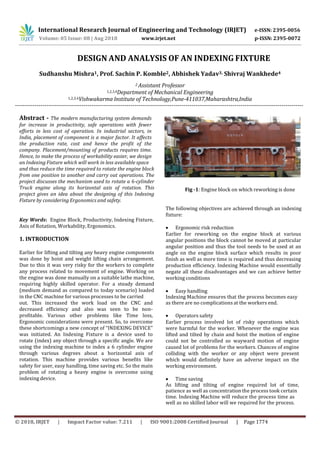
- 1. International Research Journal of Engineering and Technology (IRJET) e-ISSN: 2395-0056 © 2018, IRJET | Impact Factor value: 7.211 | ISO 9001:2008 Certified Journal | Page 1774 DESIGN AND ANALYSIS OF AN INDEXING FIXTURE Sudhanshu Mishra1, Prof. Sachin P. Komble2, Abhishek Yadav3, Shivraj Wankhede4 2 Assistant Professor 1,2,3,4Department of Mechanical Engineering 1,2,3,4Vishwakarma Institute of Technology,Pune-411037,Maharashtra,India --------------------------------------------------------------------------------------------------------------------------------------------------- Abstract - The modern manufacturing system demands for increase in productivity, safe operations with fewer efforts in less cost of operation. In industrial sectors, in India, placement of component is a major factor. It affects the production rate, cost and hence the profit of the company. Placement/mounting of products requires time. Hence, to make the process of workability easier, we design an Indexing Fixture which will work in less available space and thus reduce the time required to rotate the engine block from one position to another and carry out operations. The project discusses the mechanism used to rotate a 6-cylinder Truck engine along its horizontal axis of rotation. This project gives an idea about the designing of this Indexing Fixture by considering Ergonomics and safety. Key Words: Engine Block, Productivity, Indexing Fixture, Axis of Rotation, Workability, Ergonomics. 1. INTRODUCTION Earlier for lifting and tilting any heavy engine components was done by hoist and weight lifting chain arrangement. Due to this it was very risky for the workers to complete any process related to movement of engine. Working on the engine was done manually on a suitable lathe machine, requiring highly skilled operator. For a steady demand (medium demand as compared to today scenario) loaded in the CNC machine for various processes to be carried out. This increased the work load on the CNC and decreased efficiency and also was seen to be non- profitable. Various other problems like Time loss, Ergonomic considerations were present. So, to overcome these shortcomings a new concept of “INDEXING DEVICE” was initiated. An Indexing Fixture is a device used to rotate (index) any object through a specific angle. We are using the indexing machine to index a 6 cylinder engine through various degrees about a horizontal axis of rotation. This machine provides various benefits like safety for user, easy handling, time saving etc. So the main problem of rotating a heavy engine is overcome using indexing device. Fig -1: Engine block on which reworking is done The following objectives are achieved through an indexing fixture: Ergonomic risk reduction Earlier for reworking on the engine block at various angular positions the block cannot be moved at particular angular position and thus the tool needs to be used at an angle on the engine block surface which results in poor finish as well as more time is required and thus decreasing production efficiency. Indexing Machine would essentially negate all these disadvantages and we can achieve better working conditions Easy handling Indexing Machine ensures that the process becomes easy as there are no complications at the workers end. Operators safety Earlier process involved lot of risky operations which were harmful for the worker. Whenever the engine was lifted and tilted by chain and hoist the motion of engine could not be controlled so wayward motion of engine caused lot of problems for the workers. Chances of engine colliding with the worker or any object were present which would definitely have an adverse impact on the working environment. Time saving As lifting and tilting of engine required lot of time, patience as well as concentration the process took certain time. Indexing Machine will reduce the process time as well as no skilled labor will we required for the process. Volume: 05 Issue: 08 | Aug 2018 www.irjet.net p-ISSN: 2395-0072
- 2. International Research Journal of Engineering and Technology (IRJET) e-ISSN: 2395-0056 © 2018, IRJET | Impact Factor value: 7.211 | ISO 9001:2008 Certified Journal | Page 1775 Z2=251.5 mm Table -1: Engine Specifications Engine Family QSK-23 Engine configuration In line,4-Cycle, 6 cylinder Displacement 23.2 L HP Range Diesel 760 – 950 Gas N/A Fuel system Pressure Time (PT) Dimensions(mm) 1859 X 940 X 1656 mm (length x width x height) Weight(Kg) 2858 kg Emission Non-Certified(Industrial) IMO Tier II (Marine) Markets Earth movers Excavators Road pavers 1.1 TORQUE AND POWER CALCULATIONS WEIGHT OF BASIC COMPONENTS: WEIGHT OF FRAME: 63 Kg WEIGHT OF LH HOUSING: 80 Kg WEIGHT OF FIXTURE BASE: 280 Kg WEIGHT OF LH INDEX PLATE: 80 Kg WEIGHT OF RH INDEX PLATE: 80 Kg WEIGHT OF RH HOUSING: 95 Kg TOTAL WEIGHT OF INDEXING MACHINE AFTER MACHINING= 1302.81 Kg WEIGHT OF ENGINE BLOCK= 700 Kg First we need to find the centre of mass of the whole system with engine and indexing machine combined. For the calculation of centre of mass we need to consider a reference axis. The components that are rotating only contribute to the calculation of centre of mass. The rotating components are the fixture base and the engine block and the right and left hand side housing. The basic requirement to calculate the torque is the moment due to the weights of indexing machine and the engine that is located on the machine about the centre of mass. Then, we need to calculate the centre of mass of indexing machine and the engine. Centre of mass of indexing machine is calculated through CATIA In which the assembly is done and then centre of mass is calculated. The centre of mass co-ordinates of engine is given as input variables. The axis of rotation is known in our co-ordinate system. Centre of mass of indexing Machine: X1=68.125 mm Y1=633.346 mm Z1=202.83 mm Centre of mass of engine: X2=471 mm Y2=699.68 mm Axis of Rotation: HEIGHT (X COORDINATE)(Hx)= 308.1 mm HORIZONTOL DIRECTION (Z COORDINATE)(Hz)= 254 mm RADIUS OF ROTATION OF INDEXING MACHINE (WITH REFERENCE TO ROTATIONAL AXIS) (L1) =((Hx-X1)2 + (Hz-Z1)2)1/2 = 245.36 mm RADIUS OF ROTATION OF ENGINE (WITH REFERENCE TO ROTATIONALAXIS) (L2) =((Hx-X1)2 + (Hz-Z1)2)1/2 = 162.91 mm Fig -2: Designation of axes and center of mass and axis of rotation Maximum Torque Calculation: WEIGHT OF ENGINE(M2) = 700 kg WEIGHT OF INDEXING MACHINE(M1) = 1302.781 kg Total Torque = Torque exerted by indexing machine (T1) + Torque exerted by the engine block loaded (T2) Torque will be maximum for an angle of 90 degrees. Torque exerted by indexing machine (T1) = (M1)*g*(L1)*sinϴ = (1302.781*9.81*245.36*SIN((90*3.14)/180))/1000 =3135.89 N-m Torque exerted by indexing machine (T1) = (M2)*g*(L2)*sinϴ = (700*9.81*162.91*SIN ((90*3.14)/180))/1000 =1118.76 N-m Total Torque = T1 + T2 = 3135.89 + 1118.76 = 4254.66 N-m The moment acting due to weight is calculated by multiplyingforce and the perpendicular distance from the Volume: 05 Issue: 08 | Aug 2018 www.irjet.net p-ISSN: 2395-0072
- 3. International Research Journal of Engineering and Technology (IRJET) e-ISSN: 2395-0056 © 2018, IRJET | Impact Factor value: 7.211 | ISO 9001:2008 Certified Journal | Page 1776 1. Overview The base bears the entire engine block on it surface. It has 4 major locators and many minor locators which are 2. Hoists useful in correctly placing the engine block on the base. 3. Fixture Bed Types of Locaters used- Rough Guide Bush (2 Nos.) 4. Left hand side indexing plate and Right hand side indexing plate Diamond Locater (2 Nos.) The base is also affixed to the Side Rings. The base is made 5. Left hand shaft and Right hand shaft up of Cast Iron. 6. Left hand housing and Right hand housing Dimensions- 1524 x 508 x 98.425 (mm) 7. Frame support Weight- 700kg (after machining) 8. Spacers . 9. Locating pins 10. Belt drive 11. Worm and worm wheel set axis of rotation. The indexing machine is going to rotate and that’s why we have calculated the torque acting for different positions of theta (angle of rotation). From these different angular positions we calculate when the maximum torque is going to act and we are designing for this value of torque. The maximum torque that is going to act is 4254 N-m for this value the power is calculated. Power (in KW) = (2*pi*N*T)/60000 = 2.22 KW For this power, we decide the motor rating. The specifications of the motor selected are: Frequency (Hz) = 50 Power = 2.22 KW Ampere = 5.4 A RPM = 705 Voltage= 4.15 (+-) 10% 1.2 Design and Selection of Components Design calculations are according to Indian Standards used for cranes and hoists and standard papers. Some Indian Standards have the direct guidelines for some components. Above components are available with standard sizes. Hence, we have to select the suitable size from the calculated values. Mechanism components are checked depending on the ultimate strength by verifying that the calculated stress does not exceed a permissible stress dependent on the breaking strength of the material used. Following general components are to be Designed, Analyzed and Selected. Fig -3: 3D Model of Indexing Machine 1.4 Hoist An electro-mechanical appliance whose principal function is the lifting or lowering or both, of loads and having a wire rope fixed between the rope drum and the load block used for lifting the load is called as an electric wire rope hoist. A Hoist is a type of a device used for lifting an object and moving it from one place to another with ease. A hoist is an assembly of rope drum, motor, and hook block. It travels over the girder. The function of the hoist is to provide the main hoisting motion i.e. to rise and lower the weight. Previously this type of hoist and pulley mechanism was used to turn the engine from vertical to horizontal position. This method had certain disadvantages as discussed earlier hence this mechanism has been replaced by indexing device. 1.5 Fixture Base 1.3 Overview Overview gives us basic idea about how the Indexing machine appears and also we have made a 3D model to get a good understanding of indexing machine structure. Modeling has been done in CATIA V5 considering the actual dimensions and constraints in the Indexing Machine. Whole structure is designed to get maximum output and also has ergonomic shape which reduces risk for the worker. Fig -4: Fixture Base (Bed) Volume: 05 Issue: 08 | Aug 2018 www.irjet.net p-ISSN: 2395-0072
- 4. International Research Journal of Engineering and Technology (IRJET) e-ISSN: 2395-0056 © 2018, IRJET | Impact Factor value: 7.211 | ISO 9001:2008 Certified Journal | Page 1777 1.6 Indexing Plates The index plates are made of Cast Iron. Both plates are of the same dimensions. The index plates have numerous through holes according to the indexing angles required. The stopper is used to lock a particular indexing position. The holes are of same diameter. The RH index plate is fixed the rotating shaft and the Fixture Base(bed). Fig -5: Index plate 1.7 Shafts The Index Plates are being given drive by two Shafts. These shafts are made from Mild Steel. They are undergoing Bending stress and Torsion stress. They are transmitting torque from input to the fixture. They are varying in diameter in successive steps to increase load carrying capacity without increasing weight Fig -6: Left and Right hand side shafts 1.8 Frame Support There are two supports given to the frame of the Indexing Machine.1st is located on the right hand side and 2nd is located on the left hand side of the Fixture Housing.1st structure supports the Right hand housing.2nd structure supports the left hand housing. Fig -7: Frame Support 1.9 Design and selection of Belt Drive Belts are used to transmit power between two shafts by means of friction. A belt drive consists of three elements – driving and driven pulleys and an endless belt, which envelopes them. Belt drives can transmit power over considerable distance between the axis of driving and driven shafts. They are simple to design and have low initial cost. For our purpose we have selected V-belts as it offers following advantages over Flat belts: The force of friction between the surfaces of the belt and V-grooved pulley is high due to wedge action. This wedging action permits a smaller arc of contact, increases the pulling capacity of the belt and consequently results in increase in the power transmitting capacity. V-belts have short Centre distance, which results in compact construction. They permit high speed reduction even up to 7:1. Flat belts are hinged, while V-belts are endless which results in smooth and quiet operation even at high operating speeds. The drive is positive because the slip is negligible due to wedge action V-belt drive can operate in any position when belt is vertical. V-belts are made of polyester fabric and cords, with rubber reinforcement. The cross-section of v-belt is shown in figure. It consists of following three parts: The central load carrying layers of polyester cords or polyester fabric, which are located on horizontal lines near the center of gravity of the belt cross-section. The surrounding layer of rubber to transmit force from cords to side walls and Outer polychloroprene impregnated elastic cover. Volume: 05 Issue: 08 | Aug 2018 www.irjet.net p-ISSN: 2395-0072
- 5. International Research Journal of Engineering and Technology (IRJET) e-ISSN: 2395-0056 © 2018, IRJET | Impact Factor value: 7.211 | ISO 9001:2008 Certified Journal | Page 1778 Table -2: Dimensions of Standard cross-sections The dimensions for the cross-section of V-belt are shown in figure below. The following notations are used for the dimensions of the cross-section: Pitch Width (Wp) : It is the width of the belt at its Belt section Pitch Width Wp(mm) Nominal Top Width W(mm) Nominal Height T (mm) Recommended Minimum Pitch Diameter of Pulley (mm) Permissible Minimum Pitch Diameter of Pulley(mm) Z 8.5 10 6 85 50 pitch zone. This is the basic dimension for A 11 13 8 125 75 standardization of belt and corresponding pulley groove. Nominal Top Width (W): It is the top width of the trapezium outlined on the cross-section of the belt. Nominal Height (T): It is the height of the trapezium outlined on the cross-section of the belt. Pitch Length (Lp): It is the length of the pitch line of the belt. Angel of belt (A): It is the included angle obtained by extending the sides of the belt. Fig -8: Cross-section of V-Belt The manufacturers and the bureau of Indian standards have standardized the dimensions of the cross-section. The cross-sectional dimensions are given in table below. There are six basic symbols –Z,A,B,C,D and E – for the cross-section of V-belts’-section belts are occasionally used for low power transmission and small pulley diameter while A,B,C,D and E section belts are widely used as general purpose belts. Fig -9: Dimensions of V-Belt B 14 17 11 200 125 C 19 22 14 315 200 D 27 32 19 500 355 E 32 38 23 630 500 The selection of the cross-section depends upon two factors, namely, the power to be transmitted and speed of the faster shaft. Figure below shows the range of speed and power for various cross-sections of the belt. Depending upon the power and speed of the faster pulley, a point can be plotted on this diagram and the corresponding cross-section selected. Fig 10 -: Selection of Cross-section of V-belt i. Determining correction factor according to service. Light duty and operational hours 10- 16h.Therefore Fa=1.1 ii. Design power = Fa*(transmitted power) = 1.1*2.2 = 2.42 KW iii. From the design power and input speed the cross- section of the belt is decided. The cross-section chosen is of A type. iv. For type A cross-section Pitch width (Wp)= 11mm Nominal Top width (W)= 13 mm Nominal Height (T)= 8 mm Recommended minimum pitch diameter of pulley = 125 mm Permissible minimum pitch diameter of pulley = 75 mm Therefore, diameter of smaller pulley(d)= 125 mm v. Diameter of larger pulley(D)= D*(Speed of smaller pulley/Speed of Bigger pulley) = 125*(705/350) = 251.78 mm Volume: 05 Issue: 08 | Aug 2018 www.irjet.net p-ISSN: 2395-0072
- 6. International Research Journal of Engineering and Technology (IRJET) e-ISSN: 2395-0056 © 2018, IRJET | Impact Factor value: 7.211 | ISO 9001:2008 Certified Journal | Page 1779 Speed of Faster Shaft Power Rating for smaller pulley pitch diameter power increment per for speed ratio of 100 mm 106 mm 112 mm 118 mm 125 mm 2.00 and over rpm KW KW KW KW KW KW 500 0.67 0.72 0.79 0.86 0.93 0.06 600 0.78 0.85 0.93 1.00 1.08 0.07 700 0.88 0.96 1.05 1.14 1.23 .09 800 0.82 0.98 1.08 1.18 1.27 0.10 (D-d)/C Arc of contact on smaller pulley degrees Correction 0.00 180 1.00 0.05 177 0.99 0.10 174 0.99 0.15 171 0.98 vi. Preferred values : d=125 mm D= 250 mm Table -3: Preferred pitch diameters of pulley Belt section Z A B C D E 100 112 125 200 355 500 112 118 132 212 375 530 125 125 140 224 400 560 140 132 150 236 425 600 160 140 160 250 450 630 Table -4: Nominal pitch lengths forstandard sizesofV-belts x. Determining the correction factor (Fc) for belt pitch length from .It depends upon the type of cross-section and the pitch length of belt. Fc = 1.09 xi. Now calculating the arc of contact for the smaller pulley by the following relationship: α = 180 – 2* xii. Also determine the correction factor (Fd) for the arc of contact from .It is not advisable to use an arc of contact less than 120 degrees for V-belt drive. Therefore, the minimum arc of contact should be 120 degrees. xiii. Depending upon the type of cross-section refer to the respective table and determine the power rating Pr of single V-belt. It depends upon three factors – speed of faster shaft, pitch diameter of smaller pulley and the speed ratio. Pr = 1.23 + 0.09 = 1.32 Table -6: Power Ratings in KW (Pr) for A-section V-belts vii. Determining the pitch length of belt L by the following relationship, L = 2C + 3.14*(D+d)/2 + {(D-d)^2}/4C where C is the centre distance available. The available centre distance is 1000 mm Therefore Pitch length (L)= 2592.94 viii. Comparing the above value of pitch length from preferred pitch length is taken. In case of a non standard value the nearest value of pitch length should be taken. Therefore, L = 2570 mm ix. Now finding out the correct centre distance by substituting the above value of L in the following equation: L = 2C + 3.14*(D+d)/2 + {(D-d)^2}/4C It is a quadratic equation in C 2C^2 – 1980.951C + 3906.25 = 0 C = 988.49 mm Table -5: Correction factor for belt pitch length(Fc) xiv. The last step in the selection procedure is to find out the number of belts. It depends upon the design power and the power transmitting capacity of one belt. The number of belts is obtained by the following relationship: Number of belts (N)= {(P*Fa)/(Pr*Fc*Fd)} P= 2.42 KW Fa= 1.1 Pr= 1.32 KW Fc= 1.09 Fd= 0.98 Therefore, N= 1.887 or 2 Table -7: Correction factor for arc of contact (Fd) Correction Factor Belt pitch length(mm) Belt cross-section Z A B C D E 1.07 1080 8410 9950 1.08 2480 3200 5380 1.09 2570 9140 10710 1.10 2700 3600 1.11 6100 Pitch length of Belts Lp (mm) Z A B C D E 920 2300 2180 2190 2740 4660 1080 2480 2300 2420 3130 5040 1330 2570 2500 2720 3330 5420 1420 2700 2700 2880 3730 6100 Volume: 05 Issue: 08 | Aug 2018 www.irjet.net p-ISSN: 2395-0072
- 7. International Research Journal of Engineering and Technology (IRJET) e-ISSN: 2395-0056 © 2018, IRJET | Impact Factor value: 7.211 | ISO 9001:2008 Certified Journal | Page 1780 1.10 Design and selection of Gear Drive Worm gear drives are used to transmit power between two non intersecting shafts which are in general at right angles to each other. A speed reduction as high as 100:1 can be obtained with a single pair of worm gears. Worm gear drives are compact with small overall dimensions compared with equivalent spur or helical gear drives having same speed reduction. The operation is smooth and silent. Provision can be made for self locking operation, where the motion is transmitted only from the worm to the worm wheel. Single threaded worm gives large speed reduction, however the efficiency is low and multi threaded worm gives high efficiency however the speed reduction is low. The terminology for worm and worm wheel is : Z1= NUMBER OF STARTS ON THE WORM Z2= NUMBER OF TEETH ON WORM WHEEL Φ = PRESSURE ANGLE ϒ = LEAD ANGLE P1 = AXIAL PITCH OF WORM P2= CIRCULAR PITCH OF WORM WHEEL L = LEAD D1 = DIAMETER OF WORM D2 = DIAMETER OF WORM WHEEL C = CENTRE DISTANCE i = GEAR RATIO(Z2/Z1) m = Module Fig -11: Worm Gear Terminology Fig -12: Maximum Worm lead angle and worm gear lewis form factor for various pressure angles Fig -13: Minimum number of teeth in worm gear form factor for various pressure angles Φ = 20 degrees Power to be transmitted(P) = 2.2 KW Maximum lead angle = 25 degrees Lewis form factor(y) = 0.125 Modified Lewis form factor(Y) = 0.393 The maximum lead angle ,Lewis form factor and modified Lewis form factor are preferred. i = (350/5)= 70:1 We have chosen single start threads because the velocity ratio is more than 20. Z1=1 ; Z2= i*Z1 = 70 w1 = (2*3.14*350)/60 = 36.65 rad/s Centre distance of 250 mm is assumed. The condition for D1 is : (C^0.875)/3 ≤ D1≤ (C^0.875)/1.7 D1≥ 42mm and D1≤75 mm Therefore D1 = 60 mm is taken Axial pitch of the worm should be equal to the circular pitch of worm wheel P2= 15 mm m = P2/3.14 = 4.77 or 5mm D2= m*Z2 = 350 mm Actual centre distance (C) = 0.5*(D1+D2) = 205 mm Lead (L) = P1*Z1 = 15 mm ϒ = = 4.54 degrees Helix angle = 90 – ϒ = 85.46 degrees Helix angle should be limited to 6 degrees per thread therefore there should be at least 14 threads. Fig -14: Engine block mounted on Indexing Fixture for Reworking Volume: 05 Issue: 08 | Aug 2018 www.irjet.net p-ISSN: 2395-0072
- 8. International Research Journal of Engineering and Technology (IRJET) e-ISSN: 2395-0056 © 2018, IRJET | Impact Factor value: 7.211 | ISO 9001:2008 Certified Journal | Page 1781 2. ERGONOMICS Ergonomics is a scientific discipline, which is concerned with improving the productivity, health, safety and comfort of people, as well as promoting effective interaction among people, technology and the environment in which both must operate. By studying previous method we found out various drawbacks relating to it and by designing Indexing Machine we can eliminate all these drawbacks. Indexing Machine helps to eliminate: (a)Errors in machining (b) Awkward position of working block (c) Poor access or inadequate clearance and excessive reach, (d) Increased time in setting up of tool for various angular positions Therefore, the Indexing Fixture that is selected should be suitable for the types of tasks performed and be adaptable to multi-purpose use. Office workstations must be designed carefully to meet the need of the staff and to accomplish the goals of the facility. Design objectives should support humans to achieve the operational objectives for which they are responsible. There are three goals to consider in human-centered design. • Enhance human abilities • Overcome human limitations • Foster user acceptance Productivity of a production system is analogous to the efficiency of a machine. Just as it is desired to increase the efficiency of a machine, it is also aimed to raise the productivity within the available resources .Productivity may be defined as the ratio between output and input. Output means the amount produced or the number of items produced and inputs are the various resources employed eg, land and building, equipment and machinery, materials ,labor etc. Productivity can be increased through the use of improved tools, simple attachment and other devices. Total production times can be cut short considerably by improving machine setting up methods, thereby reducing set-up times. Proper Maintenance will add to the productivity. Productivity = (Actual production)/(Standard Production) Engine Blocks produced per shift with current Indexing Fixture = 6 per shift Engine Blocks produced per shift without current Indexing Fixture = 4 per shift Shift = 8 hours = 480 mins Standard timeor the target time that should be spend on per engine block = 60 mins Productivity without current Indexing Fixture (P1): Actual Production = 4 Standard Production = 480/60 = 8 P1 (%) = (4/8)*100 = 50 % Productivity with current Indexing Fixture (P2): Actual Production = 6 Standard Production = 480/60 = 8 P2 (%) = (6/8)*100 = 75 % Therefore we can see that P2 is greater than P1 which shows us that productivity has increased by 25 % because of the current Indexing Machine that is being employed in the production plan. 3. ANALYSIS substance into smaller parts in order to gain a better understanding of it. The technique has been applied in the study of mathematics and logic since before Aristotle, though analysis as a formal concept is a relatively recent development. Analysts in the field of engineering look at requirements, structures, mechanisms, systems and dimensions. Electrical engineers analyze systems in electronics. Life cycles and system failures are broken down and studied by engineers. It is also looking at different factors incorporated within the design. Engineering analysis involves the application of scientific analytic principles and processes to reveal the properties and state of a system, device or mechanism under study. Engineering analysis is decomposition; it proceeds by separating the engineering design into the mechanisms of operation or failure, analyzing or estimating each component of the operation or failure mechanism in isolation, and re-combining the components according to basic physical principles and natural laws. 3.1 Analysis of Index Plates a) Left Hand Side Index Plate Analysis Conditions: Maximum Force acting on Plate = 6916.45 N Supports = Bearings on Shafts. Results Obtained: Displacement = 6.23 * 10-2 mm Stress = 2.091N/mm2 Volume: 05 Issue: 08 | Aug 2018 www.irjet.net p-ISSN: 2395-0072 Analysis is the process of breaking a complex topic or
- 9. International Research Journal of Engineering and Technology (IRJET) e-ISSN: 2395-0056 © 2018, IRJET | Impact Factor value: 7.211 | ISO 9001:2008 Certified Journal | Page 1782 Fig -15: LH Index Plate Analysis The index plate is safe from failure as the stress in it does not exceed the ultimate tensile strength (250MPa). As the stress induced is less than the cyclic stress (154 MPa) of the material i.e. Cast Iron, the chances of Fatigue Failure is negligible. As the machine undergoes cyclic loading chances of Fatigue Failure are present but as crosschecked by analysis, the life of the component will be more than 106 b) Right Hand Side Index Plate Analysis Conditions: Maximum Force acting on Plate = 6916.45 N Supports = Bearings on Shafts. Results Obtained: Displacement = 7.38 * 10-2 mm Stress = 2.197N/mm2 Fig -16: RH Index Plate Analysis The index plate is safe from failure as the stress in it does not exceed the ultimate tensile strength(250MPa).As the stress induced is less than the cyclic stress(154 MPa) of the material i.e. Cast Iron, the chances of Fatigue Failure is negligible. As the machine undergoes cyclic loading chances of Fatigue Failure are present but as crosschecked by analysis, the life of the component will be more than 106. 3.1 Analysis of Shafts a) Right Hand Side Shaft (Driven Shaft) Analysis Conditions: Maximum Torque acting on shaft = 4254.66 Nm Supports = Bearings on Shafts. Results Obtained: Displacement = 3.72 * 10-5 mm Stress = 4.89 * 10-2 N/mm2 Fig -17: Stress Analysis Fig -18: Displacement Analysis b) Left Hand Side Shaft (Driving Shaft) Analysis Conditions: Maximum Torque acting on shaft = 4254.66 Nm Supports = Bearings on Shafts. Results Obtained: Displacement = 6.67 * 10-2 mm Fig -19: Displacement Analysis Volume: 05 Issue: 08 | Aug 2018 www.irjet.net p-ISSN: 2395-0072
- 10. International Research Journal of Engineering and Technology (IRJET) e-ISSN: 2395-0056 © 2018, IRJET | Impact Factor value: 7.211 | ISO 9001:2008 Certified Journal | Page 1783 Fig -20: Stress Analysis Fig -21: Analysis Parameters All the parts are safe from failure as the stress in them does not exceed the ultimate tensile strength.As the stress induced is less than the respective cyclic stresses of the material, the chances of Fatigue Failure is negligible. As the machine undergoes cyclic loading chances of Fatigue Failure are present but as crosschecked by analysis, the life of the components will be more than 106.Hence we arrive to the conclusion that the design will be safe 3. CONCLUSIONS This project will help to streamline the manufacturing process. It will help cater the rising demand of the market by the increasing the production rate. The productivity is increased by 25 %. By thorough analysis of the parts we can ensure high fatigue life for the fixture. We gained knowledge about the designing and optimizing various parts of the machine. This project helped us to gain decent exposure to various Engineering fields like: Ergonomics, Design, Analysis, Manufacturing and Safety. It helped us to get familiar with the actual industrial conditions. ACKNOWLEDGEMENT It would have been very difficult for us to make this project alone. We are dutifully obliged to all the people who helped us directly or indirectly in making this project successful. We received helping hand from many people who were eager to help us out through our queries. We would like to thank our head of mechanical department Prof Dr S.R.Bahulikar, for guidance in our course which has really helped us to be apply our knowledge practically. We would like to thank our guide Prof. S.P.Komble without whose abled and much-needed guidance our project would not have been successful as now. REFERENCES [1] VB Bhandari, Design Of Machine Elements,Third Edition,McGraw Hill Education (India),2010,pp. 499- 540,730-745. [2] American Chain Association , ‘Chains for Power transmission and materials handling’(Marcel Dekker), Second Edition, 2004, pp. 76-81. [3] Buckingham E.,Manual on Gear Design,A.G.M.A and Industrial Press,1959,pp. 92-96 [4] Dudley D.W.,Practical Gear Design,Mcgraw- Hill,1954,pp. 341-345 [5] Dudley D.W.,Gear Handbook,Mcgraw-Hill,1962., pp. 49-51 [6] Merrit H.E.,Gear Engineering ,Pitman,1971,pp. 7-11 [7] Norton R.L.,Design of Machinery,Tata-Mcgraw- Hill,2005,pp. 38-50. [8] Simon Rajguru, Hrishikesh Yadav, Priyesh Yadav, Design and Study of a Turn over Device to Tilt the Locomotive Engine from Vertical Position to Horizontal Position by Considering Ergonomics and Safety, IJSRD - International Journal for Scientific Research & Development| Vol. 4, Issue 04, 2016 [9] www.engineeringstackexchange.com/questions/6537 /what-are-inside-and-outside-dimensions-in- reference-to-castings [10] http://khkgears.net/product-category/worm-gear- pair/ [11] http://www.brighthubengineering.com/cad-autocad- reviews-tips/31792-how-to-work-with-layers-in- autocad-2009/ Volume: 05 Issue: 08 | Aug 2018 www.irjet.net p-ISSN: 2395-0072
- 11. International Research Journal of Engineering and Technology (IRJET) e-ISSN: 2395-0056 © 2018, IRJET | Impact Factor value: 7.211 | ISO 9001:2008 Certified Journal | Page 1784 BIOGRAPHIES B.Tech (Mechanical Engineering), Department Of Mechanical Engineering,Vishwakarma Institute of Technology,Pune, Maharashtra, India Assistant Professor, Department Of Mechanical Engineering,Vishwakarma Institute of Technology,Pune, Maharashtra, India B.Tech (Mechanical Engineering), Department Of Mechanical Engineering,Vishwakarma Institute of Technology,Pune, Maharashtra, India B.Tech (Mechanical Engineering), Department Of Mechanical Engineering,Vishwakarma Institute of Technology,Pune, Maharashtra, India Volume: 05 Issue: 08 | Aug 2018 www.irjet.net p-ISSN: 2395-0072