Design and Analysis of Helicopter Rotor Mechanism
•
0 likes•8 views

https://www.irjet.net/archives/V9/i8/IRJET-V9I811.pdf

Recommended
Recommended
More Related Content
Similar to Design and Analysis of Helicopter Rotor Mechanism
Similar to Design and Analysis of Helicopter Rotor Mechanism (20)
More from IRJET Journal
More from IRJET Journal (20)
Recently uploaded
Recently uploaded (20)
Design and Analysis of Helicopter Rotor Mechanism
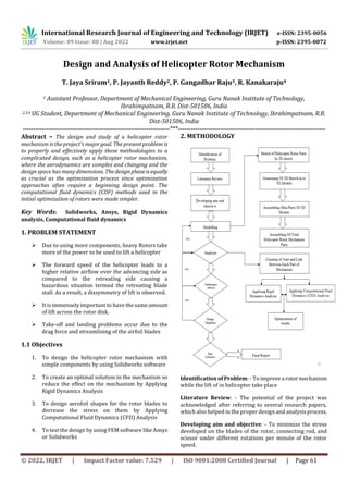
- 1. International Research Journal of Engineering and Technology (IRJET) e-ISSN: 2395-0056 Volume: 09 Issue: 08 | Aug 2022 www.irjet.net p-ISSN: 2395-0072 © 2022, IRJET | Impact Factor value: 7.529 | ISO 9001:2008 Certified Journal | Page 61 Design and Analysis of Helicopter Rotor Mechanism T. Jaya Sriram1, P. Jayanth Reddy2, P. Gangadhar Raju3, R. Kanakaraju4 1 Assistant Professor, Department of Mechanical Engineering, Guru Nanak Institute of Technology, Ibrahimpatnam, R.R. Dist-501506, India 2,3,4 UG Student, Department of Mechanical Engineering, Guru Nanak Institute of Technology, Ibrahimpatnam, R.R. Dist-501506, India ---------------------------------------------------------------------***--------------------------------------------------------------------- Abstract – The design and study of a helicopter rotor mechanism is the project's major goal. The present problem is to properly and effectively apply these methodologies to a complicated design, such as a helicopter rotor mechanism, where the aerodynamics are complex and changing and the design space has many dimensions. Thedesignphaseisequally as crucial as the optimization process since optimization approaches often require a beginning design point. The computational fluid dynamics (CDF) methods used in the initial optimization of rotors were made simpler. Key Words: Solidworks, Ansys, Rigid Dynamics analysis, Computational fluid dynamics 1. PROBLEM STATEMENT Due to using more components, heavy Rotors take more of the power to be used to lift a helicopter The forward speed of the helicopter leads to a higher relative airflow over the advancing side as compared to the retreating side causing a hazardous situation termed the retreating blade stall. As a result, a dissymmetry of lift is observed. It is immensely important to have the same amount of lift across the rotor disk. Take-off and landing problems occur due to the drag force and streamlining of the airfoil blades 1.1 Objectives 1. To design the helicopter rotor mechanism with simple components by using Solidworks software 2. To create an optimal solution in the mechanism so reduce the effect on the mechanism by Applying Rigid Dynamics Analysis 3. To design aerofoil shapes for the rotor blades to decrease the stress on them by Applying Computational Fluid Dynamics (CFD) Analysis 4. To test the design by using FEM software like Ansys or Solidworks 2. METHODOLOGY Identification of Problem: - To improvea rotormechanism while the lift of in helicopter take place Literature Review: - The potential of the project was acknowledged after referring to several research papers, which also helped in the proper design and analysisprocess. Developing aim and objective: - To minimize the stress developed on the blades of the rotor, connecting rod, and scissor under different rotations per minute of the rotor speed.
- 2. International Research Journal of Engineering and Technology (IRJET) e-ISSN: 2395-0056 Volume: 09 Issue: 08 | Aug 2022 www.irjet.net p-ISSN: 2395-0072 © 2022, IRJET | Impact Factor value: 7.529 | ISO 9001:2008 Certified Journal | Page 62 Modeling: - designing software SOLIDWORKS was used for the designing of all the components in helicopter rotor mechanisms Analysis: - Analysis of the components was done by using ANSYS software under Rigid Dynamics Analysis and Computational Fluid Dynamics (CFD) Analysis Performance analysis:-Byusingtheiterationmethodlarge number of iterations were performed and performance analysis was carried out. Design validation: - The data collected using the iterative method was used to finalize the design and respective changes were made in the model for better performance. Data collection: - To gather themeasuringdata,andanalyze accurate data from a variety of relevant sources of analysis Final report: - The project report is written evidence of tasks, processes, and activities that are undertaken and accomplished while pursuing their projects and implementing them in the project work 3. MODELLING OF HELICOPTER MECHANISMS 3.1 Design of helicopter mechanism components The helicopter rotor mechanics consists of different components in it. these components are used to construct of rotor mechanism. In the process, we have first created a 2D sketch of the components and these components are generated into 3D model parts from the 2D sketch. After designing the 3D model, we assembled the parts into a mini assembly by getting together small parts into a single assembly. Then these single assemblies are used to create a major assembly of the helicopter rotor mechanism. These are the components used in the helicopter mechanism Anti-Rotation Bracket Ball Holder Lower Half Ball Holder Upper Half Ball Base Bearing For Main Shaft Bearing Bottom Swash Collar Control Rod Horizontal Link Vertical Link Linkage Ball Linkage Ball-Extended Linkage Ball-For Servo Arm Main Rotor Housing Main Shaft Pitch Rod Rod End Rotor Blade Rotor Holder Arm Rotor Holder Servo Link Servo Motor Upper Swash Connector Upper Swash Fasteners Rotor Head Fasteners Horizontal Vertical Link Fasteners 3.1.1 Anti-Rotation Bracket The anti-rotation bracket according to thepresentinvention prevents rotating concerning an appliance in which it is installed. The bracket includes a U-shaped member, an attachment mechanism for securing the U-shaped member to an appliance, and at least one clip extending from each of two legs of the U-shaped member for securing a rectangular crimped section of a joint. Fig 1 Anti-Rotation Bracket 3.1.2 Ball Holder Lower Half The ball holder's lower half is used to hold and allow to rotate in it. the ball is attached to the main shaft of the rotor and it rotates concerning the main shaft of the helicopter. The holder is like a disk shape. It is located below the ball and above the Swashplate
- 3. International Research Journal of Engineering and Technology (IRJET) e-ISSN: 2395-0056 Volume: 09 Issue: 08 | Aug 2022 www.irjet.net p-ISSN: 2395-0072 © 2022, IRJET | Impact Factor value: 7.529 | ISO 9001:2008 Certified Journal | Page 63 Fig 2 Ball Holder Lower Half 3.1.2 Ball The ball joint is attached to the main shaft rotor of the helicopter mechanism. It is located between the two balls holder. It revolves around the main shaft speed and helps to swash plates not to rotate them just to move in the direction Fig 3 Ball 3.1.3 Base The base is used to stabilize the mechanism. All the compounds are assembled and these are held on the base platform. The base provides support to the mechanism and the rotation of the main shaft for the mechanism Fig 4 Base 3.1.4 Bottom Swash A swashplate is a device that translates input via the helicopter flight controls into the motion of the main rotor blades. Because the main rotor blades are spinning, the swashplate is used to transmit threeofthepilot'scommands from the non-rotating fuselage to the rotating rotor hub and main blades. Fig 5 Bottom Swash 3.1.5 Control Rod The control rod assembly has a control rod which is provided between a swash plate-side bearing center and a rotor blade side bearing center. An axle housing has an eccentric structure that is accommodated in a swash plate- side bearing center and a bearing structure that is accommodated in a swash plate-side bearing block. Fig 6 Control Rod 3.1.6 Main Rotor Housing A helicopter main rotor or rotorsystemisthecombinationof several rotary wings (rotor blades) with a control system, that generates the aerodynamic lift force that supports the weight of the helicopter, and the thrust that counteracts aerodynamic drag in forwarding flight.
- 4. International Research Journal of Engineering and Technology (IRJET) e-ISSN: 2395-0056 Volume: 09 Issue: 08 | Aug 2022 www.irjet.net p-ISSN: 2395-0072 © 2022, IRJET | Impact Factor value: 7.529 | ISO 9001:2008 Certified Journal | Page 64 Fig 7 Main Rotor Housing 3.1.7 Rotor Blade The blades of a helicopter are long, narrow airfoils with a high aspect ratio, a shape that minimizes drag from tip vortices. They generally contain a degree of washout that reduces the lift generated at the tips, where the airflow is fastest and vortex generation would be a significant problem. Fig 8 Rotor Blade 3.2 Major Assembly of The Whole Compound’s Open solidworks > file > click on assembly model > Go to assembly menu > click on insert components > select on Base mini assembly > place on the origin point >click OK > click on insert components > select on swash plate mini assembly > click on mate > select on required mate for both mini assembly > click OK > click on insert components > select on Control Rod mini assembly > click on mate > select on required mate for both mini assembly > click OK > click on insert components > select on Pitch mini assembly>click on mate > select on required mate for both mini assembly > click OK > click on insert components > select on Horizontal vertical mini assembly > click on mate > select on required mate for both mini assembly > click OK > click on insert components > select on Rotor Blade’s>click onmate>select on required mate for rotor holder > click OK > click on insert components > select on Rotor Blade’s 2 > click on mate > select on required mate for rotor holder > click OK Fig 9 Major assembly of the whole compound’s 5. ANALYSIS OF HELICOPTER MECHANISM 5.1 Rigid dynamic Analysis of the mechanism Utilize the power of the rigid dynamics explicit solver for efficient and robust evaluation of mechanical systems containing complex assemblies of interconnectedrigidparts undergoing large overall motion. Apply procedures for analysis of machine and mechanism systems such as vehicle suspensions, landing gear assemblies, roboticmanipulators, and engine components. 5.1.1 Process of rigid dynamic analysis 1. Engineering Data Engineering data is the data of the selected material properties, we have chosen the structural steel because the main concept is to test the mechanism inAnsys.Itisa default material in the Ansysworkbench.Thefollowingfigureshows the properties of the material Fig 10 Material properties of structural steel The geometry is the file import from the assembled helicopter mechanism in the Solidworks file which is converted into the STP file for a more accurate model, STP file makes Ansys mesh the object very fine to get the better results 2. Geometry
- 5. International Research Journal of Engineering and Technology (IRJET) e-ISSN: 2395-0056 Volume: 09 Issue: 08 | Aug 2022 www.irjet.net p-ISSN: 2395-0072 © 2022, IRJET | Impact Factor value: 7.529 | ISO 9001:2008 Certified Journal | Page 65 Fig 11 mechanism Geometry 3. Model Model is the next step of the geometry which allows the geometry to constrain the joint with each link by using the revolution joint, fixed link, cylindrical joint, and spherical joint which makes the parts move and rotate as the helicopter motion like a lift and land Fig 12 Model of the mechanism 4. Setup After assigning all joint constraints to every part the setup is the next. We give the rotation magnitude to the joint as loads and no of steps assigning Table 1 Setup Values Fig 13 Time vs Rotation graph 5.2 Computational Fluid Dynamics (CFD) Analysis of Rotors 5.2.1 Process of Computational Fluid Dynamics (CFD) 1. Geometry Once you have your physics defined you must create a two or three-dimensional geometry that is dependent on your problem analysis. Some problems are solvable in two dimensions, which can save time and money through reduced computational needs.WeusetheSolidworksdesign module in Ansys Fig 14 Geometry of rotor 2. Meshing Meshing requires a great deal ofcarebecauseitcanhave a cascading effect on your analysis if done improperly. This step involves establishing the physical domain of your environment into defined regions called cells, or control volumes. These cells are further defined by the fluid flow equations inside that govern them - requiring the designer to make a proper assumption about their flow profiles. Most designers find that keeping these cells as small as possible can help you ensure accuracy throughout the analysis
- 6. International Research Journal of Engineering and Technology (IRJET) e-ISSN: 2395-0056 Volume: 09 Issue: 08 | Aug 2022 www.irjet.net p-ISSN: 2395-0072 © 2022, IRJET | Impact Factor value: 7.529 | ISO 9001:2008 Certified Journal | Page 66 Fig 15 Meshing 3. Setup In this stage, we will have to define the conditions of the problems we want to solve. For example, transient one- phase, stationary or multiphase, turbulence model, fluid type, and boundary conditions. It is essential to know the physics of the problem because the numerical solutions are pre-configured. Moreover, we havetoknowhowthemethod works. When it comes to processing, we can choose the processors to use and thenecessaryiterations whenitcomes to achieving convergence. Fig 16 Setup 6. RESULTS AND DISCUSSION The helicopter rotor mechanics consists of different components in it. these components are used to construct of rotor mechanism. In this process, we have first created a 2D sketch of the components and these components are generated into 3D model parts from the 2D sketch. After designing the 3D model, we assembled the parts into a mini assembly by getting together small parts into a single assembly. Then these single assemblies are used to create a major assembly of the helicopter rotor mechanism. Wehave designed every component by using Solidworkssoftware. In Solidworks, we have used different entities to design and model a component. We first model simple and individual components with some design standards this are related to the main component. Then this component is attached to sub-assemblies with related components this process will reduce the effect on the constructionofthemainassembly to avoid confusion and constraints in the assembly. Then these sub-assemblies are together into a single assembly as the main assembly. Hence the final helicoptermechanismpartis assembled and has a mechanical movement. We have used the Ansys software to test the mechanism with Rigid dynamic Analysis and Computational Fluid Dynamics (CFD) Analysis Results 6.1 Rigid dynamic Analysis Result The results on the mechanism and got the total deformation, total velocity, and total acceleration. By using Rigid dynamic Analysis Total Deformation result Fig 17 Time vs total deformation graph The above graph is shown the total deformation in the helicopter mechanism the deformation takes on the y-axis and time in x- the axis. the deformation will increase according to the time on the x-axis the maximum and average deformation occurs at 10 seconds at 2.96150 mm and 2.26410 mm. the values are shown in the table below
- 7. International Research Journal of Engineering and Technology (IRJET) e-ISSN: 2395-0056 Volume: 09 Issue: 08 | Aug 2022 www.irjet.net p-ISSN: 2395-0072 © 2022, IRJET | Impact Factor value: 7.529 | ISO 9001:2008 Certified Journal | Page 67 Table 2 Maximum and Average Total Velocity Velocity Probe Result of Rotor Blade Fig 18 Time vs velocity of the rotor blade graph The above graph is shown the velocity probe result of rotor blade 1 in the helicopter mechanismthevelocityprobetakes on the y-axis and time in x- the axis. the velocity will decrease very gradually according to the time on the x-axis the different axis velocity occurs at 10 seconds at the x-axis is 0.0010 mm/s and on the y-axis is 0.01974 mm/s and on the z-axis is -0.04138 mm/s 6.2 Computational Fluid Dynamics (CFD) Analysis Results We have done the results on the rotor blades and got the streamline, density of air, dynamic viscosity of air, velocity, total pressure, velocity Axial, velocity Radial, andviewofthe flow. By using CFD analysis Fig 19 views of streamlines The above streamline is in straight line flow there are less turbulent flow so there is a proper flow according to every streamline and its own property’s and according to this the streamlines are moved and showed Velocity Fig 19 velocity of streamlines In the above velocity result. we have gota maximumvelocity of 2.205 m/s and a minimum velocity of 0.00 m/s Total Pressure Fig 20 Total Pressure of streamlines In the above total pressure result. We have got maximum total pressure of 2.709 Pa and a minimum total pressure of - 1.322 Pa
- 8. International Research Journal of Engineering and Technology (IRJET) e-ISSN: 2395-0056 Volume: 09 Issue: 08 | Aug 2022 www.irjet.net p-ISSN: 2395-0072 © 2022, IRJET | Impact Factor value: 7.529 | ISO 9001:2008 Certified Journal | Page 68 7. CONCLUSIONS The main goal was to find the total deformation,velocity,and acceleration with reducing heavy componentswhichimpact the main rotor. Within the frame of analysis, aerodynamic computationanalyseswere made.Differentconfigurationsof the main rotor and flow conditions were investigated. The obtained results may be very useful to design simple helicopter mechanics. But the most important reason is to use of obtained results to further analysis like the dynamic analysis. Analysis which includes both stability of the main rotor The global conclusion from this project is that the rotating components like the main rotor havea biginfluence on the static stability. BIOGRAPHIES JAYANTH REDDY PINGILI, UG Student, Department of Mechanical Engineering, Guru Nanak Institute of Technology, Ibrahimpatnam, R.R.Dist- 501506, India GANGDHAR RAJU PEDDAMALLA, UG Student, Department of Mechanical Engineering, Guru Nanak Institute of Technology, Ibrahimpatnam, R.R.Dist- 501506, India RACHAKONDA KANAKARAJU, UG Student, Department of Mechanical Engineering, Guru Nanak Institute of Technology, Ibrahimpatnam, R.R.Dist- 501506, India