Downloaded 636 times
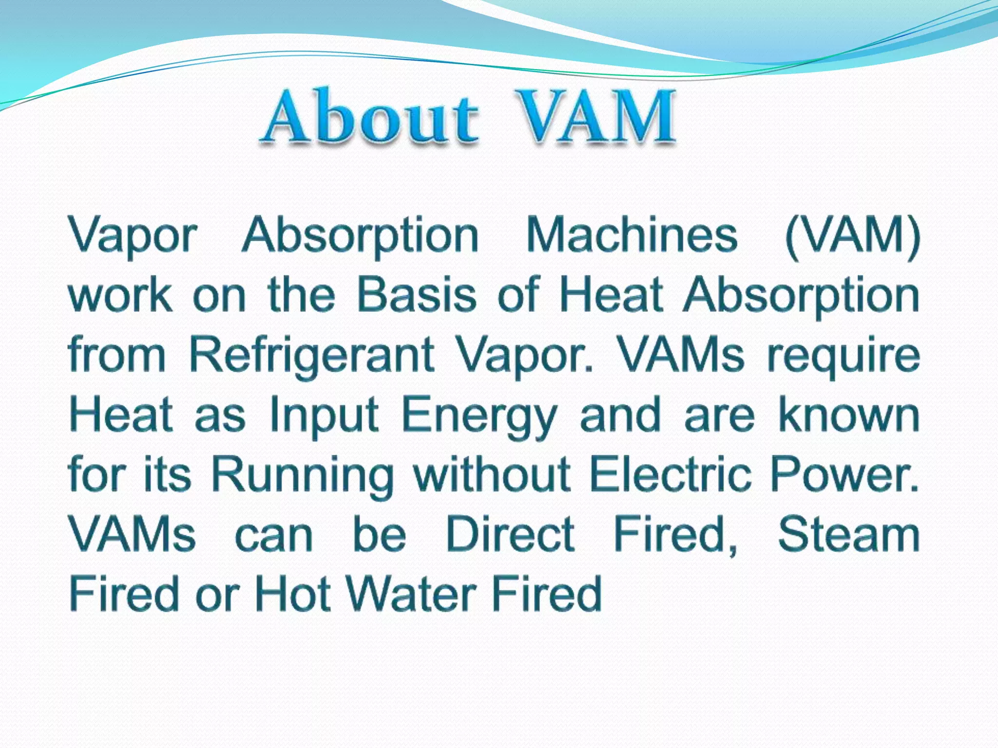
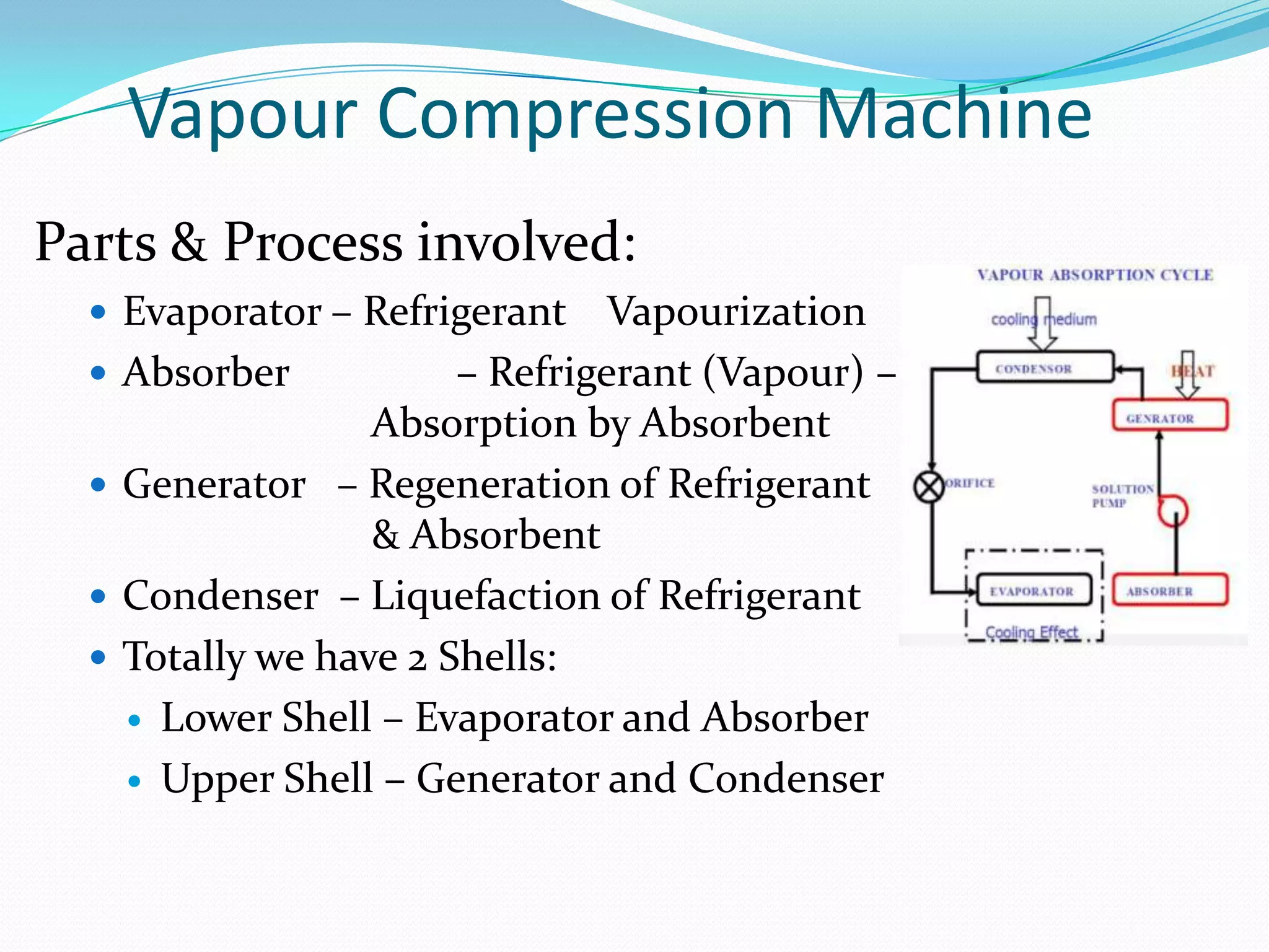
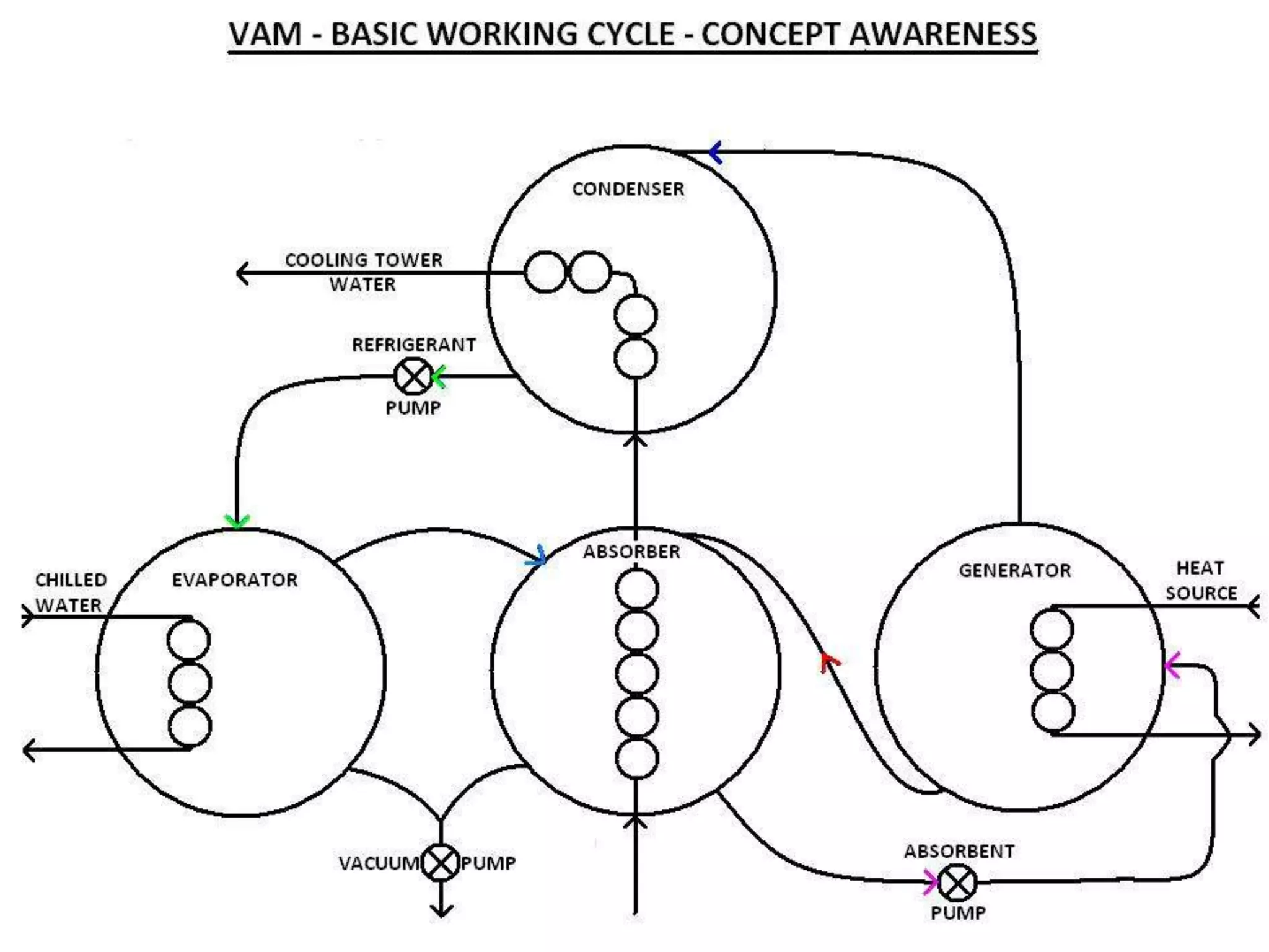
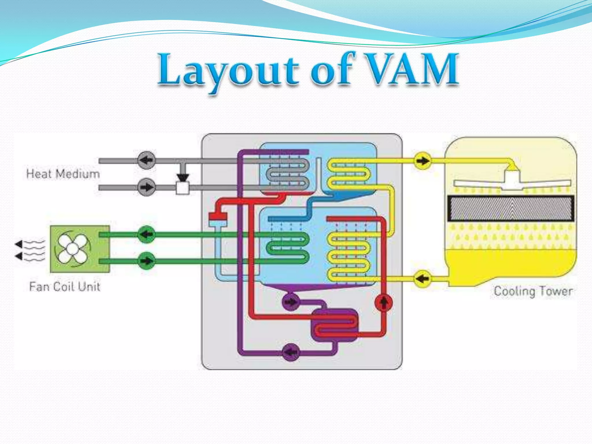
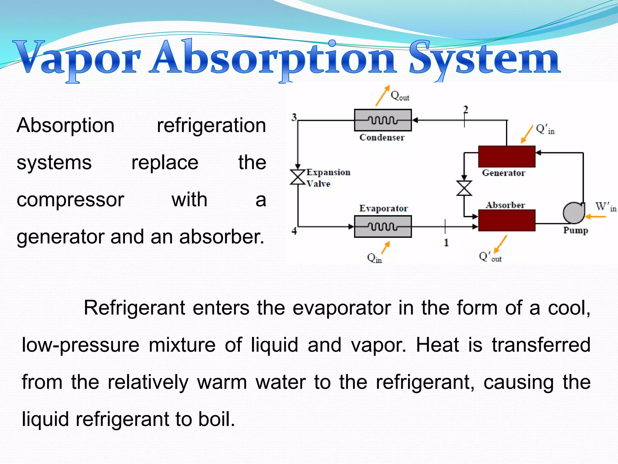
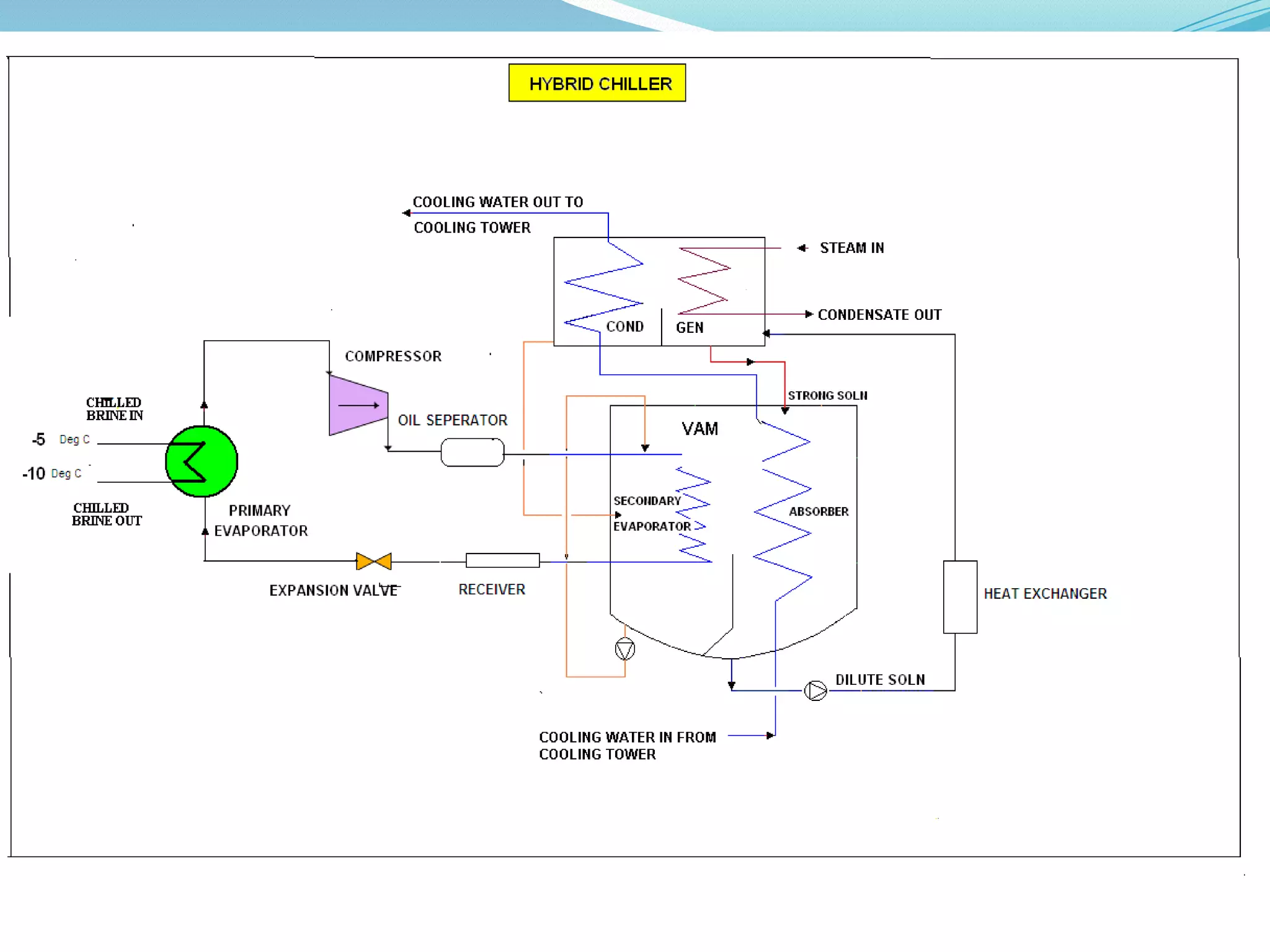
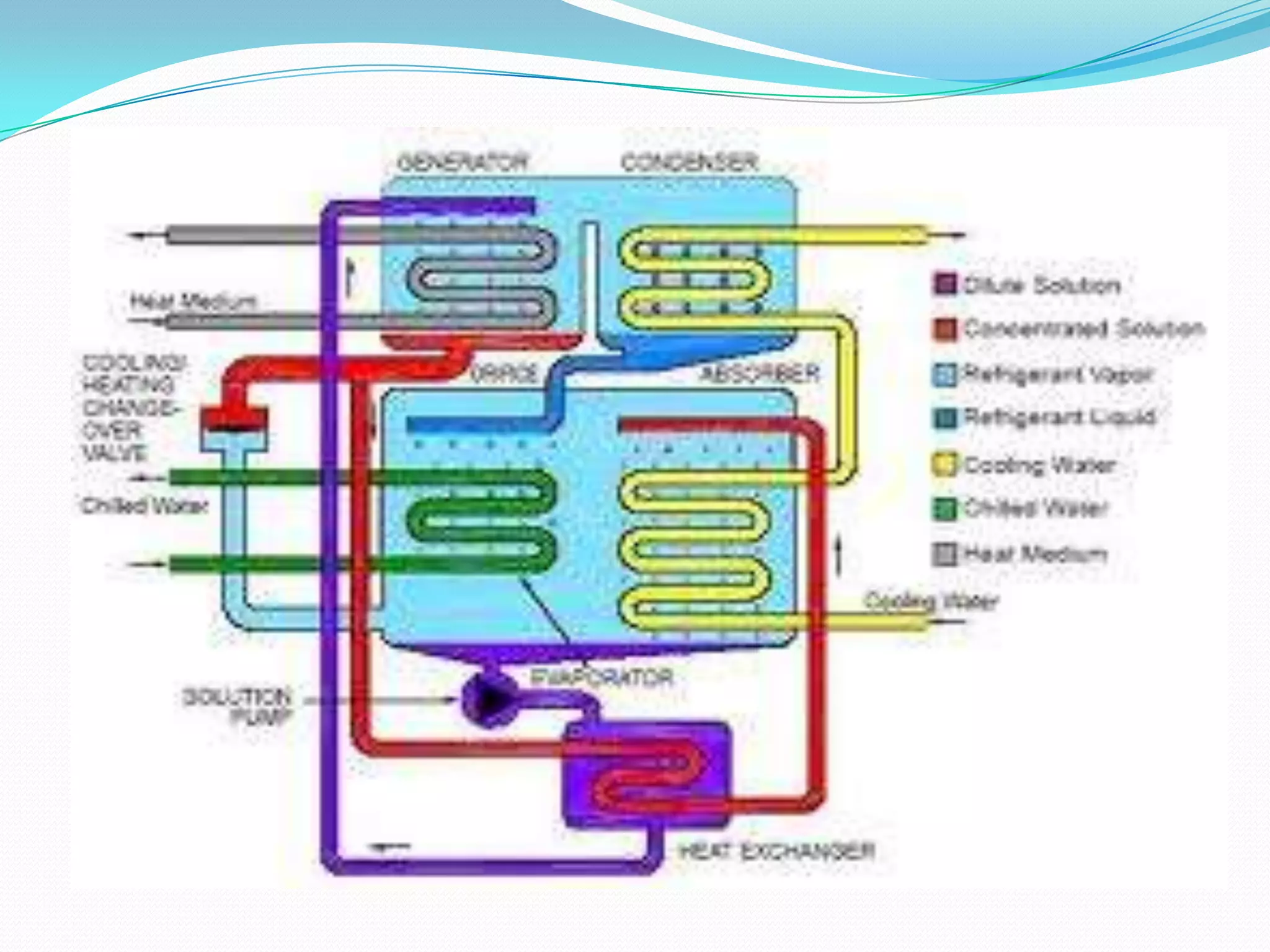


The document describes the key components and processes in a vapor absorption refrigeration system: 1) An evaporator where refrigerant vaporizes and absorbs heat, 2) An absorber where refrigerant vapor is absorbed by an absorbent, releasing heat, 3) A generator where heat regenerates the refrigerant and absorbent, and 4) A condenser where refrigerant condenses and liquefies. Heat from a heat source like steam drives the process without the need for a compressor.


![Coded Agents – with UiPath SDK + LangGraph [Virtual Hands-on Workshop]](https://cdn.slidesharecdn.com/ss_thumbnails/codedagentsdeck-251215155422-5497c599-thumbnail.jpg?width=640&height=640&fit=bounds)


![Vibe Coding vs. Spec-Driven Development [Free Meetup]](https://cdn.slidesharecdn.com/ss_thumbnails/vibecodingvsspecdrivendevelopment-251209105622-43f455e7-thumbnail.jpg?width=640&height=640&fit=bounds)


