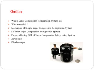
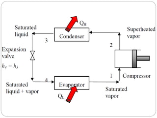
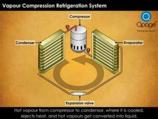
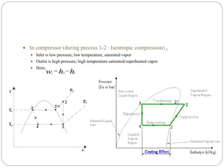
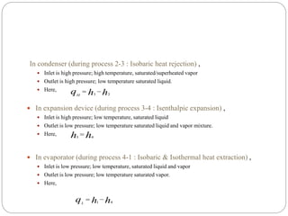
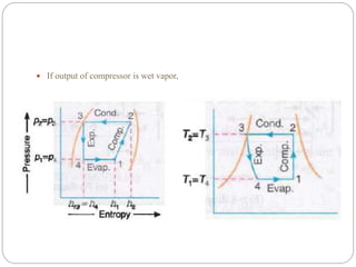
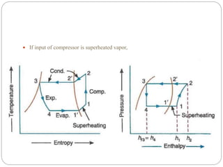
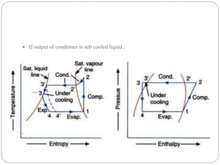
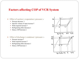
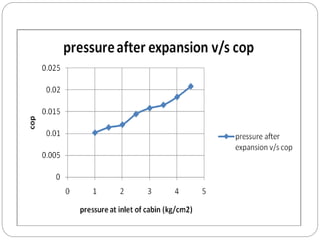
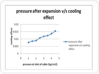
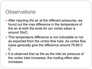
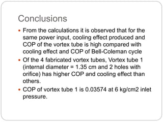
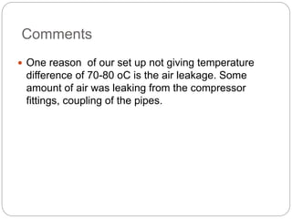
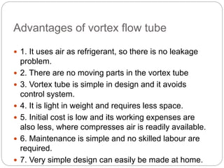
This document provides an overview of a vapor compression refrigeration system. It defines what a vapor compression refrigeration system is, why it is needed compared to other refrigeration cycles, and describes the basic mechanism and components. The key components discussed are the compressor, condenser, expansion device, and evaporator. It also covers factors that affect the coefficient of performance and provides some advantages and disadvantages.
Project report on vcr system with liquid suction heat exchangerSant Lal Patel
vapour compression refrigeration system with liquid suction heat exchanger is benificial for engineering students .it is a final year project of mechanical engineering.
Ammonia refrigeration plant installed in NDRI,KARNAL.
designed by Arghya & Kartik.
this explains the specifications of refrigeration units like Compressor, Condenser, Expansion Valves and Evaporators.their specification and working.
Even advantages of ammonia has been explained.
Presentation Outline:-
The Principles of Basic Refrigeration
Basic Refrigeration Cycle
There are countless applications for refrigeration plants now.
How do things get colder
Main Components
Accessories
Pressure
Pressure And Temperature
Refrigerator used for Cooling
Analysis of the Carnot Refrigerator
Terminology
The Vapor Compression Refrigeration Cycle
The Pressure-Enthalpy Diagram
Vapor Compression Refrigeration Analysis
VCR Cycle Irreversibilities
The COP of the refrigeration increasing the performance and to get high efficiency of the refrigeration system. By using nano coating over the evaporator of the refrigeration component the objective can be achieved. The improper heat dissipation occurred in the heat exchanger components causes effect in performance. The vapour compression refrigeration system consuming the high power. Though the energy taken for the refrigeration process has increased and leads to more power consumption. In order to increase the performance, Nano coating Copper Oxide has been applied over the evaporator. By applying the Nano coating Copper Oxide over the evaporator the COP increased. In result the energy required for the refrigeration process and global warming problems has been reduced. By addition of nanoparticles to the refrigeration results in improvements in the COP of the refrigeration, thereby improving the performance of the refrigeration system. In this experiment the effect of using CuO-R134a in the vapour compression system expected COP will be increased by 5% with nano coating.
Need for cooling of an aircraft. types of air-refrigeration system, DART, Advantages of air refrigeration system, Open and closed cycle air refrigeration,
What is first law of Thermodynamics?
What is a Thermodynamic cycle?
Types of Thermodynamic cycles
What is a Refrigeration Cycle?
Types of Refrigeration cycles
What is a Refrigeration System?
Principle of working of a Refrigeration System
Other Refrigeration systems
Refrigeration is a process of moving heat from one location to another in controlled conditions. The work of heat transport is traditionally driven by mechanical work, but can also be driven by heat, magnetism, electricity, laser, or other means. Air conditioning (often referred to as AC, A.C., or A/C) is the process of removing heat from a confined space, thus cooling the air, and removing humidity.
Vapor compression refrigeration cycle, Refrigerants,
Coefficient of performance, Capacity, Factors affecting Refrigeration and Air conditioning
system performance and savings opportunities.
Vapor absorption refrigeration system: Working principle, Types and comparison with
vapor compression system, Saving potential
Hybrid optimization of pumped hydro system and solar- Engr. Abdul-Azeez.pdffxintegritypublishin
Advancements in technology unveil a myriad of electrical and electronic breakthroughs geared towards efficiently harnessing limited resources to meet human energy demands. The optimization of hybrid solar PV panels and pumped hydro energy supply systems plays a pivotal role in utilizing natural resources effectively. This initiative not only benefits humanity but also fosters environmental sustainability. The study investigated the design optimization of these hybrid systems, focusing on understanding solar radiation patterns, identifying geographical influences on solar radiation, formulating a mathematical model for system optimization, and determining the optimal configuration of PV panels and pumped hydro storage. Through a comparative analysis approach and eight weeks of data collection, the study addressed key research questions related to solar radiation patterns and optimal system design. The findings highlighted regions with heightened solar radiation levels, showcasing substantial potential for power generation and emphasizing the system's efficiency. Optimizing system design significantly boosted power generation, promoted renewable energy utilization, and enhanced energy storage capacity. The study underscored the benefits of optimizing hybrid solar PV panels and pumped hydro energy supply systems for sustainable energy usage. Optimizing the design of solar PV panels and pumped hydro energy supply systems as examined across diverse climatic conditions in a developing country, not only enhances power generation but also improves the integration of renewable energy sources and boosts energy storage capacities, particularly beneficial for less economically prosperous regions. Additionally, the study provides valuable insights for advancing energy research in economically viable areas. Recommendations included conducting site-specific assessments, utilizing advanced modeling tools, implementing regular maintenance protocols, and enhancing communication among system components.
TECHNICAL TRAINING MANUAL GENERAL FAMILIARIZATION COURSEDuvanRamosGarzon1
AIRCRAFT GENERAL
The Single Aisle is the most advanced family aircraft in service today, with fly-by-wire flight controls.
The A318, A319, A320 and A321 are twin-engine subsonic medium range aircraft.
The family offers a choice of engines
Explore the innovative world of trenchless pipe repair with our comprehensive guide, "The Benefits and Techniques of Trenchless Pipe Repair." This document delves into the modern methods of repairing underground pipes without the need for extensive excavation, highlighting the numerous advantages and the latest techniques used in the industry.
Learn about the cost savings, reduced environmental impact, and minimal disruption associated with trenchless technology. Discover detailed explanations of popular techniques such as pipe bursting, cured-in-place pipe (CIPP) lining, and directional drilling. Understand how these methods can be applied to various types of infrastructure, from residential plumbing to large-scale municipal systems.
Ideal for homeowners, contractors, engineers, and anyone interested in modern plumbing solutions, this guide provides valuable insights into why trenchless pipe repair is becoming the preferred choice for pipe rehabilitation. Stay informed about the latest advancements and best practices in the field.
Automobile Management System Project Report.pdfKamal Acharya
The proposed project is developed to manage the automobile in the automobile dealer company. The main module in this project is login, automobile management, customer management, sales, complaints and reports. The first module is the login. The automobile showroom owner should login to the project for usage. The username and password are verified and if it is correct, next form opens. If the username and password are not correct, it shows the error message.
When a customer search for a automobile, if the automobile is available, they will be taken to a page that shows the details of the automobile including automobile name, automobile ID, quantity, price etc. “Automobile Management System” is useful for maintaining automobiles, customers effectively and hence helps for establishing good relation between customer and automobile organization. It contains various customized modules for effectively maintaining automobiles and stock information accurately and safely.
When the automobile is sold to the customer, stock will be reduced automatically. When a new purchase is made, stock will be increased automatically. While selecting automobiles for sale, the proposed software will automatically check for total number of available stock of that particular item, if the total stock of that particular item is less than 5, software will notify the user to purchase the particular item.
Also when the user tries to sale items which are not in stock, the system will prompt the user that the stock is not enough. Customers of this system can search for a automobile; can purchase a automobile easily by selecting fast. On the other hand the stock of automobiles can be maintained perfectly by the automobile shop manager overcoming the drawbacks of existing system.
Student information management system project report ii.pdfKamal Acharya
Our project explains about the student management. This project mainly explains the various actions related to student details. This project shows some ease in adding, editing and deleting the student details. It also provides a less time consuming process for viewing, adding, editing and deleting the marks of the students.
Overview of the fundamental roles in Hydropower generation and the components involved in wider Electrical Engineering.
This paper presents the design and construction of hydroelectric dams from the hydrologist’s survey of the valley before construction, all aspects and involved disciplines, fluid dynamics, structural engineering, generation and mains frequency regulation to the very transmission of power through the network in the United Kingdom.
Author: Robbie Edward Sayers
Collaborators and co editors: Charlie Sims and Connor Healey.
(C) 2024 Robbie E. Sayers
Sachpazis:Terzaghi Bearing Capacity Estimation in simple terms with Calculati...Dr.Costas Sachpazis
Terzaghi's soil bearing capacity theory, developed by Karl Terzaghi, is a fundamental principle in geotechnical engineering used to determine the bearing capacity of shallow foundations. This theory provides a method to calculate the ultimate bearing capacity of soil, which is the maximum load per unit area that the soil can support without undergoing shear failure. The Calculation HTML Code included.
Democratizing Fuzzing at Scale by Abhishek Aryaabh.arya
Presented at NUS: Fuzzing and Software Security Summer School 2024
This keynote talks about the democratization of fuzzing at scale, highlighting the collaboration between open source communities, academia, and industry to advance the field of fuzzing. It delves into the history of fuzzing, the development of scalable fuzzing platforms, and the empowerment of community-driven research. The talk will further discuss recent advancements leveraging AI/ML and offer insights into the future evolution of the fuzzing landscape.
Industrial Training at Shahjalal Fertilizer Company Limited (SFCL)MdTanvirMahtab2
This presentation is about the working procedure of Shahjalal Fertilizer Company Limited (SFCL). A Govt. owned Company of Bangladesh Chemical Industries Corporation under Ministry of Industries.
Event Management System Vb Net Project Report.pdfKamal Acharya
In present era, the scopes of information technology growing with a very fast .We do not see any are untouched from this industry. The scope of information technology has become wider includes: Business and industry. Household Business, Communication, Education, Entertainment, Science, Medicine, Engineering, Distance Learning, Weather Forecasting. Carrier Searching and so on.
My project named “Event Management System” is software that store and maintained all events coordinated in college. It also helpful to print related reports. My project will help to record the events coordinated by faculties with their Name, Event subject, date & details in an efficient & effective ways.
In my system we have to make a system by which a user can record all events coordinated by a particular faculty. In our proposed system some more featured are added which differs it from the existing system such as security.
3. Refrigeration & Air Conditioning
Simple Vapor Compression Refrigeration
System
4. Outline
What a Vapor Compression Refrigeration System is ?
Why its needed ?
Mechanism of Simple Vapor Compression Refrigeration System
Different Vapor Compression Refrigeration System
Factors affecting COP of Vapor Compression Refrigeration System
Advantages
Disadvantages
5. What a VCR System is ?
Its improved refrigeration cycle which uses fluid instead of air as working
substance.
These systems belong to the general class of vapor cycles, wherein the working
refrigerant undergoes phase change at least during one process. The working
substance is circulated in the system in which it alternatively evaporates and
condenses; thus it undergoes a phase change.
Refrigeration is obtained as the refrigerant evaporates at low temperatures.
The input to the system is in the form of mechanical energy required to run the
compressor. Hence these systems are also called as mechanical refrigeration
systems.
6. Why its needed ?
In Carnot refrigeration system,
Isothermal heat rejection process requires slow piston movement
Reversible adiabatic ( Isentropic ) process requires faster piston movements
Above both are not possible.
For generating maximum possible COP, Carnot cycle can be referred as an
ideal.
Also, working substance; air/gas is only compressible whereas vapor is
compressible as well as it can change phase during different process.
Phase change of fluid during evaporation process requires large amount of
heat, hence if temperature of fluid is reduced then refrigeration effect can be
increased.
Also, isothermal vaporization allows extraction of heat without raising
temperature of fluid very high.
7. Mechanism of Simple VCRS
Assumptions for ideal vapor-compression cycle are ;
Irreversibility within the evaporator, condenser and compressor are ignored
no frictional pressure drops
refrigerant flows at constant pressure through the two heat exchangers (evaporator and
condenser)
heat losses to the surroundings are ignored
compression process is isentropic
Main components are;
Compressor
Condenser
Expansion Devices
Evaporator
10. In compressor (during process 1-2 : Isentropic compression) ,
Inlet is low pressure; low temperature, saturated vapor
Outlet is high pressure; high temperature saturated/superheated vapor.
Here,
hhwc 12
11. In condenser (during process 2-3 : Isobaric heat rejection) ,
Inlet is high pressure; high temperature, saturated/superheated vapor
Outlet is high pressure; low temperature saturated liquid.
Here,
In expansion device (during process 3-4 : Isenthalpic expansion) ,
Inlet is high pressure; low temperature, saturated liquid
Outlet is low pressure; low temperature saturated liquid and vapor mixture.
Here,
In evaporator (during process 4-1 : Isobaric & Isothermal heat extraction) ,
Inlet is low pressure; low temperature, saturated liquid and vapor
Outlet is low pressure; low temperature saturated vapor.
Here,
hhqH 23
hh 43
hhqL 41
15. If input of compressor is superheated vapor,
16. If output of condenser is sub cooled liquid ,
17. Factors affecting COP of VCR System
Effect of suction ( evaporation ) pressure :-
Pressure decrease ↓
Specific volume of vapor increase ↑
Work required increase ↑
Refrigerating effect decrease ↓
Hence, COP decrease ↓
Effect of discharge ( condenser ) pressure :-
Pressure increase ↑
Work required increase ↑
Refrigerating effect decrease ↓
Hence, COP decrease ↓
18. Effect of evaporator & condenser temperature :-
Evaporator temp. decreases ↓
Condenser temperature increases ↑
Work required increase ↑↑
Refrigerating effect decrease ↓↓
Hence, COP decrease ↓
Effect of Superheated vapor after evaporation :-
Specific volume of vapor increase ↑
Refrigerating capacity decreases ↓
Work required increase ↑
Refrigerating effect decrease ↓
Hence, COP decrease ↓
19. Effect of sub cooling :-
Refrigerating effect increase ↑
Hence, COP increase ↑
20. Advantages
Smaller size for capacity of refrigeration
Less running cost.
Large range of temperatures available.
High COP.
Less complex in design & operation.
23. Introduction
The mechanism used for lowering or producing
low temp. in a body or a space, whose temp. is
already below the temp. of its surrounding, is
called the refrigeration system.
Here the heat is being generally pumped from
low level to the higher one & is rejected at high
temp.
24. Refrigeration
The term refrigeration may be defined as the
process of removing heat from a substance under
controlled conditions.
It also includes the process of reducing heat &
maintaining the temp. of a body below the
general temp. of its surroundings.
25. Contd….
In other words the refrigeration means a
continued extraction of heat from a body whose
temp is already below the temp. of its
surroundings.
26. Refrigerator & Refrigerant
A refrigerator is a reversed heat engine or a heat
pump which takes out heat from a cold body &
delivers it to a hot body.
The refrigerant is a heat carrying medium which
during their cycle in a refrigeration system
absorbs heat from a low temp. system & delivers
it to a higher temp. system.
27. Refrigeration Cycle
In refrigeration system the heat is being generally
pumped from low level to higher one & rejected at
that temp.
This rejection of heat from low level to higher
level of temp. can only be performed with the help
of external work according to second law of
thermodynamics.
28. Contd….
The total amount of heat being rejected to the
outside body consist of two parts:-
- the heat extracted from the body to be cooled .
- the heat equivalent to the mechanical work
required for extracting it.
30. Contd….
A refrigerator is a reverse heat engine run in the
reverse direction by means of external aid.
Every type of refrigeration system used for
producing cold must have the following four basic
units:-
31. Contd….
Low temp. thermal sink to which the heat is
rejected for cooling the space.
Means of extracting the heat energy from the
sink, raising its level of temp. before delivering it
to heat receiver.
A receiver is a storage to which the heat is
transferred from the high temp., high pressure
refrigerant.
32. Contd…..
Means of reducing the pressure & temp. of the
refrigerant before it return to the sink.
The processes of the cycle are evaporation,
compression, condensation & expansion.
By reversing the heat engine cycle completely
& by changing the working agent, a refrigeration
cycle is obtained.
33. Refrigeration Systems
Vapour compression refrigeration system
Vapour absorption refrigeration system
Thermo electric refrigeration system
34. Vapour Compression
Refrigeration
This is the most important system from the point
of commercial & domestic utility & most practical
form of refrigeration.
The working fluid refrigerant used in this
refrigeration system readily evaporates &
condenses or changes alternatively between the
vapour & liquid phases without leaving the
refrigerating plant
35. Contd….
During evaporation it absorbs heat from the cold
body or in condensing or cooling it rejects heat to
the external hot body .
The heat absorbed from cold body during
evaporation is used as its latent heat for
converting it from liquid to vapour.
Thus a cooling effect is created in working fluid.
36.
37. Contd….
This system of refrigeration thus act as latent
heat pump since its pump its latent heat from
the cold body or brine & rejects it or deliver it
to the external hot body or the cooling
medium.
According to the law of thermodynamics , this
can be done only on the expenditure of
energy which is supplied to the system in the
form of electrical energy driving the
compressor.
38. Contd….
The vapour compression cycle is used in most of
the modern refrigeration systems in large
industrial plants.
The vapour in this cycle is circulated through the
various components of the system, where it
undergoes a number of changes in its state or
condition.
39. Contd….
Each cycle of operation consists of the four
fundamental changes of state or processes:-
Expansion
Vaporization
Compression
Condensation
41. Compressor
The low pressure & temp. refrigerant from
evaporator is drawn into the compressor
through the inlet or suction valve , where it is
compressed to a high pressure & temp.
The high pressure & temp vapour refrigerant
is discharged into the condenser through the
delivery or discharge valve.
42. Condenser
The condenser or the cooler consists of
coils of pipe in which the high pressure &
temp. vapour refrigerant is cooled &
condensed.
The refrigerant while passing through the
condenser, rejects its latent heat to
surrounding condensing medium which is
normally air or water.
Thus hot refrigerant vapour received from
compressor is converted into liquid form in
condenser.
43. Receiver
The condensed liquid refrigerant from the
condenser is stored in a vessel, known as
receiver, from where it is supplied to the
expansion valve or refrigerant control valve.
44. Expansion Valve
The function of this valve is to allow the liquid
refrigerant under high pressure & temp. to pass at
a controlled rate after reducing its pressure &
temp.
some of liquid refrigerant evaporates as it passes
through the expansion valve, but the greater
portion is vaporized in the evaporator at the low
pressure & temp.
45. Evaporator
An evaporator consists of coils of pipes in
which the liquid vapour refrigerant at low
pressure & temp. is evaporated & changed
into vapour refrigerant at low pressure &
temp.
During evaporation process, the liquid vapour
refrigerant absorbs its latent heat of
vaporization from the medium which is to be
cooled.
46. Advantages
Smaller size for a given refrigerating capacity
Higher coif. of performance
Lower power requirements for a given capacity
Less complexity in both design & operation
It can be used over large of temp.
47. Domestic Refrigerator
The application of refrigeration for domestic
purposes are mainly in the form of domestic
refrigerators & home freezers.
The main purpose of this type of refrigeration is to
provide low temp. for storage & distribution of
foods & drinks.
48. Contd….
It represents a significant portion of the
refrigeration industry due to the use of these units
in large number.
For domestic preservation, the storage is
generally short term. The domestic refrigerators
used for the purposes are usually small in sizes
with rating in ranges from 1/20 to ½ tonne.
49. Contd….
The unit is usually self contained and hermetically
sealed.
Due to short term storage the domestic
refrigerator load is intermittent.
50. Contd….
The requirement of domestic refrigerator is that:-
it should be simple in construction
automatic in action
nominal in initial cost
51. Contd….
dependable and without any necessity of expert
inspection & repair.
Non irritant & non toxic refrigerant should be
used.
Generally methylene chloride, freon-12, Freon -11
are used as refrigerants.
52. Contd…
The common type of domestic refrigerator have a
cabinet shaped with compressor motor-fan
assembly, the condensed and receiver fitted in
their basement.
The expansion valve evaporator coils are
exposed in the storage cabinet with the piping,
carrying liquid refrigerant passing through the
body.
53. Contd….
The heat of the bodies to be cooled is carried
to the evaporator coils by means of air
trapped in the cabinet.
Refrigeration is not only provided with double
walled cabinet packed with materials having
high thermal insulation such as fiber glass or
expanded rubber but also all around the
inside of door flap soft rubber seal is used
which makes rubber air tight.
54. Electrical Circuit
Refrigerator is provided with a door push
switch, which closes on opening of refrigerator
and puts the lamp on.
Capacitor start single phase induction motor is
used in open type refrigerators and split
phase induction motor is used in sealed unit
refrigerators.
Electromagnetic relay is provided to connect
auxiliary winding on the start & disconnect it
when the motor picks up the speed.
56. Contd…..
Thermal overload release is provided to protect
the motor from damage against flow of over
current.
Thermostat switch is provided to control the temp.
inside the refrigerator.
Temp. inside the refrigerator can be adjusted by
means of temp. control screw.
57. Contd…
To protect the motor against under voltage use of
automatic voltage regulator is essential since in
case of fall in applied voltage, motor will draw
heavy current to develop the required torque and
will become hot, thermal overload relay will
therefore repeatedly disconnect and connect the
motor to supply, eventually burning it out.
59. Introduction
Air refrigeration system generally uses air as medium,
whereas other refrigeration systems use refrigerants
(Freon’s, ammonia etc.,) as medium. Since air is used as
refrigerant no damage to atmosphere is done. By using
other refrigerants damage to atmosphere such as ozone
layer depletion takes place. Compression of air needs much
power compared to compression of refrigerants. This
system produces low COP because of which it has become
obsolete.
Other refrigeration systems have high COP but have severe
impact on atmosphere. Moreover these refrigerants are too
expensive and handling of these refrigerants is difficult.
61. Working of Bell-Coleman cycle
1. Isentropic compression process
2. Constant pressure cooling process
3. Isentropic expansion process
4. Constant pressure expansion process
62. Working of Bell-Coleman cycle
1. Isentropic compression process: The cold air from the
refrigerator or atmosphere is drawn into the compressor
cylinder where it is compressed isentropically in the
compressor as shown by the curve 1-2 on p-v and T-s
diagrams. During the compression stroke, both the pressure
and temperature increases and the specific volume of air at
delivery from compressor reduce from v1 to v2. We know that
during isentropic compression process, no heat is absorbed or
rejected by the air.
2. Constant pressure cooling process: The warm air from the
compressor is now passed into the cooler where it is cooled
at constant pressure P3 (equal to P2), reducing the
temperature from T2 to T3 (the temperature of cooling water)
as shown by the curve 2-3 on p-v and T-s diagrams. The
specific volume also reduces from v2 to v3.
63. 3. Isentropic expansion process: The air from the cooler is now
drawn into the expander cylinder where it is expanded
isentropically from pressure P3 to the refrigerator pressure P4
which is equal to the atmospheric pressure. The temperature of
the air during expansion falls from T3 to T4 shown by the curve
3-4 on p-v and T-s diagrams. The specific volume of air at entry
to the refrigerator increases from v3 to v4. We know that during
isentropic expansion of air, no head is absorbed or rejected by
the air.
4. Constant pressure expansion process: The cold air from the
expander is now passed to the refrigerator where it is expanded
at constant pressure P4 (equal to P1). The temperature of air
increases from T4to T1. This process is shown by the curve 4-
1on p-v and T-s diagrams. Due to heat from the refrigerator, the
specific volume of the air changes from v4 to v1.
64. Apparatus required
Digital Thermometers – 2
Copper tube (Heat exchanger) – 1
Air Compressor
Air regulator
Cabin
Digital Anemometer
Connecting pipes
70. Procedure of experiment
For different compressor pressures after
expansion, We calculated the Cooling effects and
COP’s by using evaporator’s inlet and outlet
temperatures.
We plotted the graphs for the same results
1) Pressure after expansion versus cooling
effect
2) pressure after expansion versus COP
71.
72.
73. Observations from Graphs
It is found out that
As inlet pressure increases, COP of Bell Coleman
cycle increases.
As inlet pressure increases, cooling effect of Bell
Coleman cycle increases.
74. Results
The Cooling effect of the Bell Coleman cycle
is found out to be 0.011 KW
The COP of the Bell Coleman cycle is found
out to be 0.015
75. VORTEX TUBE
The vortex tube is a structurally simple device with no moving parts
that is capable of separating a high-pressure flow into two lower
pressure flows with different energies, usually manifested as a
difference in temperatures. The vortex tube is relatively inefficient as a
stand-alone cooling device but it may become an important component
of a refrigeration system when employed as an alternative to the
conventional throttling valve.
77. Construction details of Vortex tube
Vortex tube has following parts:
Air Inlet
Vortex Chamber
Hot end side
Cold end side
Hot end obstruction
84. Standard Dimensions
Tube Inner diameter = D
Nozzle diameter = D/8
Orifice diameter = D/2
Cold end length = 10D
Hot end length = 45D
We have varied these dimensions and fabricated four
different vortex tubes and observed the COP’s and
Cooling effects
85. Dimensions of fabricated Vortex
tubes
Tube inner diameter (small) – 13.5mm (Tubes 1
& 2)
Tube inner diameter (Big) – 19mm (Tubes 3 & 4)
Couplings
Cold end lengths - 135mm, 190mm (rounded off
a bit)
Hot end lengths - 608mm, 855mm (rounded off a
bit)
Orifice diameter - 6.75 (Tubes 1 & 2)
Venturi diameter - D = 19mm , d = 9.5mm
95. Procedure of experiment
For four different Vortex tubes which we
fabricated, we calculated Cooling effects and
COP’s at different inlet pressures.
We also calculated mass flow rates and plotted
graphs for
1) Mass flow rates versus Temperature difference
2) COP versus Inlet pressures
and came at various conclusions.
97. COP of 4 vortex tubes at different
pressures
0
0.005
0.01
0.015
0.02
0.025
0.03
0.035
0.04
6 5 4 3 2
COP
Pressure
COP(1)
COP(2)
COP(3)
COP(4)
98. Observations
After injecting the air at the different pressures, we
found out the max difference in the temperature of
the air at both the ends for our vortex tubes is
around 35oC.
This temperature difference is not noticeable or not
as expected from the vortex flow tube. As vortex flow
tubes generally give the difference around 70-80 0
C.
It is observed that as the as the inlet air pressure of
the vortex tube increases, the cooling effect also
increases
99. Conclusions
From the calculations it is observed that for the
same power input, cooling effect produced and
COP of the vortex tube is high compared with
cooling effect and COP of Bell-Coleman cycle
Of the 4 fabricated vortex tubes, Vortex tube 1
(internal diameter = 1.35 cm and 2 holes with
orifice) has higher COP and cooling effect than
others.
COP of vortex tube 1 is 0.03574 at 6 kg/cm2 inlet
pressure.
100. Comments
One reason of our set up not giving temperature
difference of 70-80 oC is the air leakage. Some
amount of air was leaking from the compressor
fittings, coupling of the pipes.
101. Advantages of vortex flow tube
1. It uses air as refrigerant, so there is no leakage
problem.
2. There are no moving parts in the vortex tube
3. Vortex tube is simple in design and it avoids
control system.
4. It is light in weight and requires less space.
5. Initial cost is low and its working expenses are
also less, where compresses air is readily available.
6. Maintenance is simple and no skilled labour are
required.
7. Very simple design can easily be made at home.
102. Disadvantages
1. Its low COP
2. Limited capacity.
3. Small portion of the compressed air appearing as
the cold air limits its wide use in practice.
103. Applications
1. Vortex tubes are extremely small and as it
produce hot as well as cold air. It may be used in
industries where both are simultaneously
required.
2. Low temperatures can be obtained without any
difficulty, so it is very much useful in industries for
spot cooling of electronic components.
3. It is commonly used for body cooling of the
workers in mines.
104. Future scope
By using continuous discharge compressors (vane type or
gear type) we can get continuous and high air pressures.
Because of which high cooling effect and COP can be
achieved for both Bell-Coleman cycle and Vortex tube air
refrigeration system.
By using high capacity Vortex tubes, high cooling rates by
Vortex tube air refrigeration system can be achieved.
By sending the air at high pressure and low temperature
into Vortex tube, even low cold end temperatures can be
achieved.
105. References
Sl.n
o
Paper Author
1 Review on Vortex tube Refrigeration Rahul Dilip Pawar
N.C.Ghuge
2 The Application Of Vortex Tubes to
Refrigeration Cycles.
G. F. Nellis
S. A. Klein
3 Experimental Performance Study of
Vortex Tube Refrigeration System
Sankar Ram T
Anish Raj K
4 Performance Analysis of a Vortex Tube
by using Compressed Air
Ratnesh Sahu, Rohit
Bhadoria, Deepak Patel
5 An Experimental Setup of Vortex Tube
Refrigeration System
Karthik S
106. Sl no paper Author
6 Vortex tube refrigeration system
Based on Compressed air.
Tejshree Bornare,
Abhishek Badgujar,
Prathamesh Natu
7 Experimental Investigation of Vortex Tube
Refrigeration.
Sarath Sasi1, Sreejith
8 Experimental study of Bell Coleman cycle
using Air as Refrigerant
P.V.Ramana
9 Performance evaluation of refrigeration
system based on Bell coleman
Cycle
Rahul Patel
Ramji Tripathi
107. Otto Belden blog on Construction of vortex tube
Various youtube videos
various articles about vortex tube on google
Wikipedia
109. The term simple as used in Air Cycle
Refrigeration indicates a system in which the
pressure of the working fluid is raised in
two levels by using two compressors,
before the working fluid which is air,
expands in the turbine section.
Consists of a Primary Heat Exchanger, a
Secondary Heat Exchanger and a Cooling
Turbine.
Ram Air is used as a sink in the Primary and
Secondary Heat Exchangers.
110. The simple refrigeration system is mostly
used in Transport Aircrafts. The Basic
System will cool the Cabin when the
Airplane is on the Ground. The simple
system requires the Airplane to be in flight
so that the Ram Air can cool the Heat
Exchangers.
High Pressure air is first cooled in the
Primary Heat Exchanger. The air is then
compressed to a Higher Pressure and
Temperature in the compressor of the
Cooling Turbine. A substantial amount of
heat of compression is removed in the
secondary heat exchanger and the air is
cooled further as it expands through the
Turbine section of the Cooling Turbine.
112. Ambient Air state 1 is pressurized to state 2
due to the Ram Effect.
This air is further compressed to state 3 in the
main compressor.
The air is then cooled to state 4 in the air
cooler. The heat rejected in the air cooler is
absorbed by the ram air at state 2.
The air from the air cooler is further
compressed from state 4 to state 5 in the
secondary compressor.
It is then cooled to state 6 in the after cooler,
expanded to cabin pressure in the cooling
turbine and is supplied to the cabin at a low
temperature T7.
#4
115. References
Sl.n
o
Paper Author
1 Review on Vortex tube Refrigeration Rahul Dilip Pawar
N.C.Ghuge
2 The Application Of Vortex Tubes to
Refrigeration Cycles.
G. F. Nellis
S. A. Klein
3 Experimental Performance Study of
Vortex Tube Refrigeration System
Sankar Ram T
Anish Raj K
4 Performance Analysis of a Vortex Tube
by using Compressed Air
Ratnesh Sahu, Rohit
Bhadoria, Deepak Patel
5 An Experimental Setup of Vortex Tube
Refrigeration System
Karthik S
116. Sl no paper Author
6 Vortex tube refrigeration system
Based on Compressed air.
Tejshree Bornare,
Abhishek Badgujar,
Prathamesh Natu
7 Experimental Investigation of Vortex Tube
Refrigeration.
Sarath Sasi1, Sreejith
8 Experimental study of Bell Coleman cycle
using Air as Refrigerant
P.V.Ramana
9 Performance evaluation of refrigeration
system based on Bell coleman
Cycle
Rahul Patel
Ramji Tripathi
117. Otto Belden blog on Construction of vortex tube
Various youtube videos
various articles about vortex tube on google
Wikipedia