Download as PDF, PPTX
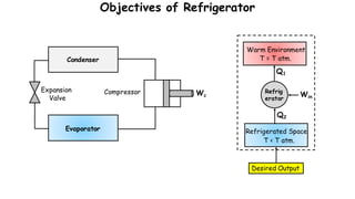
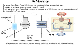
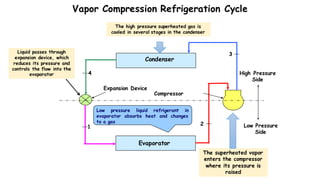
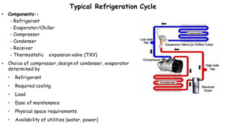
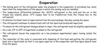
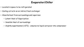
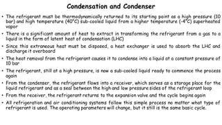
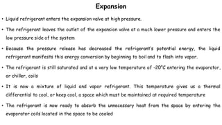
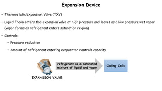
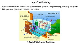
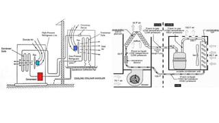
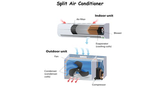
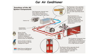

1) Refrigeration and air conditioning systems use a vapor compression cycle to transfer heat from cool spaces to warm spaces. They circulate a refrigerant between an evaporator, compressor, condenser and expansion valve. 2) In the evaporator, the refrigerant absorbs heat from cool spaces and changes state from liquid to vapor. The compressor increases the refrigerant's pressure and temperature. In the condenser, the refrigerant releases heat to warm spaces and changes state from vapor to liquid. 3) The expansion valve reduces the refrigerant's pressure, lowering its temperature. This allows it to absorb more heat in the evaporator and continue the cooling cycle. Proper refrigerant selection and system design are important


![Intern ppt ..kk [Autosaved].pptx](https://cdn.slidesharecdn.com/ss_thumbnails/internppt-231006135559-ff64c843-thumbnail.jpg?width=640&height=640&fit=bounds)


