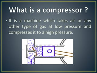
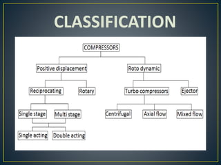
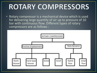
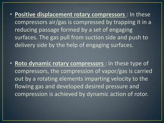
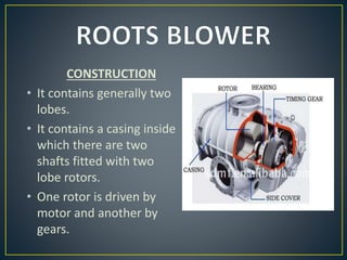
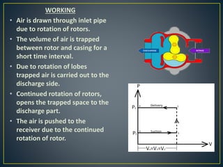
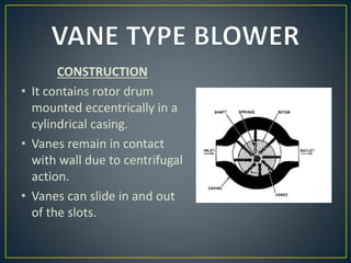
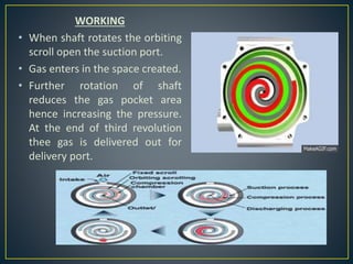
Prepared by :
Kunj Thummar
Sumit Patel
Jasvant Maliwad
Gunjan Vasava
• It is a machine which takes air or any
other type of gas at low pressure and
compresses it to a high pressure.
CLASSIFICATION
• Rotary compressor is a mechanical device which is used
for delivering large quantity of air up to pressure of 10
bar with continuous flow. Different types of rotary
compressors are as follows :
• Positive displacement rotary compressors : In these
compressors air/gas is compressed by trapping it in a
reducing passage formed by a set of engaging
surfaces. The gas pull from suction side and push to
delivery side by the help of engaging surfaces.
• Roto dynamic rotary compressors : in these type of
compressors, the compression of vapor/gas is carried
out by a rotating elements imparting velocity to the
flowing gas and developed desired pressure and
compression is achieved by dynamic action of rotor.
CONSTRUCTION
• It contains generally two
lobes.
• It contains a casing inside
which there are two
shafts fitted with two
lobe rotors.
• One rotor is driven by
motor and another by
gears.
WORKING
• Air is drawn through inlet pipe
due to rotation of rotors.
• The volume of air is trapped
between rotor and casing for a
short time interval.
• Due to rotation of lobes
trapped air is carried out to the
discharge side.
• Continued rotation of rotors,
opens the trapped space to the
discharge part.
• The air is pushed to the
receiver due to the continued
rotation of rotor.
CONSTRUCTION
• It contains rotor drum
mounted eccentrically in a
cylindrical casing.
• Vanes remain in contact
with wall due to centrifugal
action.
• Vanes can slide in and out
of the slots.
WORKING
• The rotation of rotor caused space
between vanes, the rotor and casing.
• The space is connected to the suction
pipe.
• In this space the air enters and fills the
whole space.
• With rotation the air gets compressed
due to reduction of space towards
delivery.
• The fluid volume is now reduced and
communicates with the delivery pipe.
• Due to pressure difference in
compressed air and the receiver
pressure back flow of air takes place,
which causes further rise in pressure of
internally compressed air.
• This air is now delivered to the receiver.
• CONSTRUCTION
• It contains two mating
helically grooved rotors.
• Rotors are suitably housed
in a cylinder.
• Cylinder are equipped with
appropriate suction and
discharge ports.
• Rotors are driven by
synchronized gears.
WORKING
• Gas enters from the suction
side and progressively gets
compressed as it moves
through the narrowing
passage formed by lobes.
• Compression is obtained by
following stages :
1. Suction
2. Transportation
3. Compression
4. Discharge
CONSTRUCTION
• It contains two matching scrolls.
• One of them is fixed and other free
to orbit.
• These scrolls form series of space
packets between two mounting
spirals.
• These spaces are filled by gases
while in working condition.
• Suction take space at outer edge
and delivery for center fixed port.
WORKING
• When shaft rotates the orbiting
scroll open the suction port.
• Gas enters in the space created.
• Further rotation of shaft
reduces the gas pocket area
hence increasing the pressure.
At the end of third revolution
thee gas is delivered out for
delivery port.
ROTARY COMPRESSORS

ROTARY COMPRESSORS

  • 1.
    Prepared by : KunjThummar Sumit Patel Jasvant Maliwad Gunjan Vasava
  • 2.
    • It isa machine which takes air or any other type of gas at low pressure and compresses it to a high pressure.
  • 3.
  • 4.
    • Rotary compressoris a mechanical device which is used for delivering large quantity of air up to pressure of 10 bar with continuous flow. Different types of rotary compressors are as follows :
  • 5.
    • Positive displacementrotary compressors : In these compressors air/gas is compressed by trapping it in a reducing passage formed by a set of engaging surfaces. The gas pull from suction side and push to delivery side by the help of engaging surfaces. • Roto dynamic rotary compressors : in these type of compressors, the compression of vapor/gas is carried out by a rotating elements imparting velocity to the flowing gas and developed desired pressure and compression is achieved by dynamic action of rotor.
  • 6.
    CONSTRUCTION • It containsgenerally two lobes. • It contains a casing inside which there are two shafts fitted with two lobe rotors. • One rotor is driven by motor and another by gears.
  • 7.
    WORKING • Air isdrawn through inlet pipe due to rotation of rotors. • The volume of air is trapped between rotor and casing for a short time interval. • Due to rotation of lobes trapped air is carried out to the discharge side. • Continued rotation of rotors, opens the trapped space to the discharge part. • The air is pushed to the receiver due to the continued rotation of rotor.
  • 8.
    CONSTRUCTION • It containsrotor drum mounted eccentrically in a cylindrical casing. • Vanes remain in contact with wall due to centrifugal action. • Vanes can slide in and out of the slots.
  • 9.
    WORKING • The rotationof rotor caused space between vanes, the rotor and casing. • The space is connected to the suction pipe. • In this space the air enters and fills the whole space. • With rotation the air gets compressed due to reduction of space towards delivery. • The fluid volume is now reduced and communicates with the delivery pipe. • Due to pressure difference in compressed air and the receiver pressure back flow of air takes place, which causes further rise in pressure of internally compressed air. • This air is now delivered to the receiver.
  • 10.
    • CONSTRUCTION • Itcontains two mating helically grooved rotors. • Rotors are suitably housed in a cylinder. • Cylinder are equipped with appropriate suction and discharge ports. • Rotors are driven by synchronized gears.
  • 11.
    WORKING • Gas entersfrom the suction side and progressively gets compressed as it moves through the narrowing passage formed by lobes. • Compression is obtained by following stages : 1. Suction 2. Transportation 3. Compression 4. Discharge
  • 12.
    CONSTRUCTION • It containstwo matching scrolls. • One of them is fixed and other free to orbit. • These scrolls form series of space packets between two mounting spirals. • These spaces are filled by gases while in working condition. • Suction take space at outer edge and delivery for center fixed port.
  • 13.
    WORKING • When shaftrotates the orbiting scroll open the suction port. • Gas enters in the space created. • Further rotation of shaft reduces the gas pocket area hence increasing the pressure. At the end of third revolution thee gas is delivered out for delivery port.