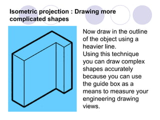
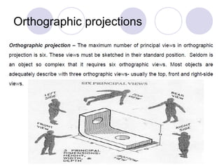
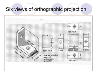
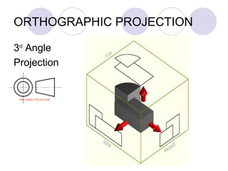
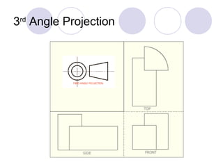
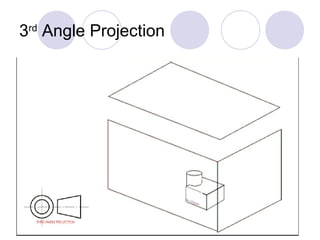
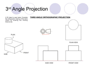
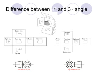
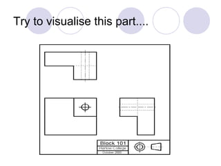
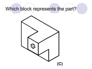
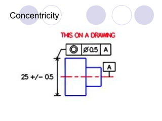
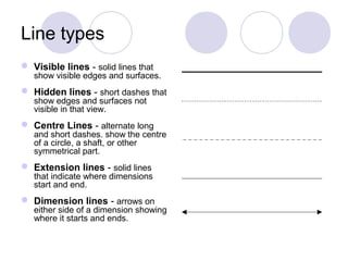
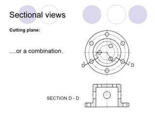
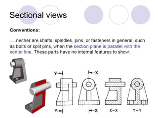
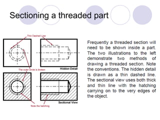
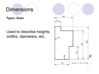
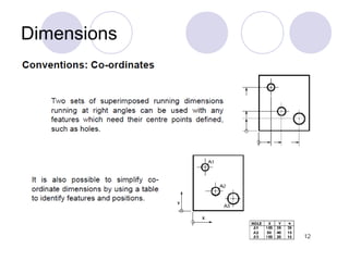
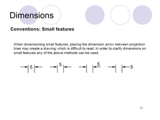
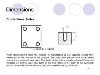
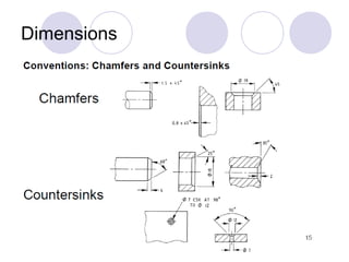
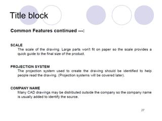
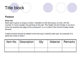
Downloaded 229 times
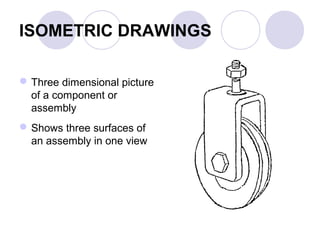
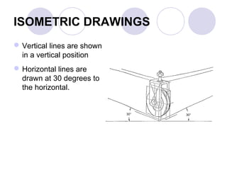
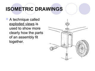

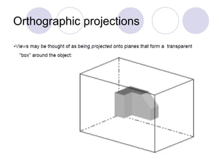

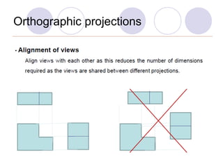
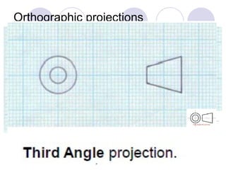
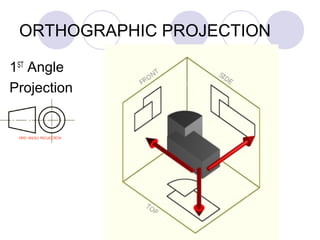
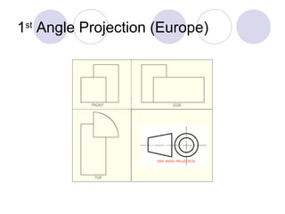
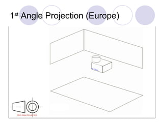
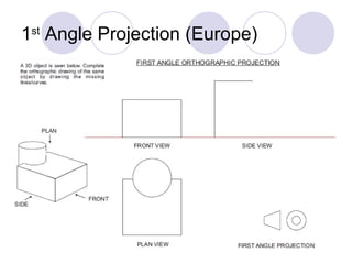
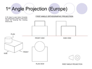

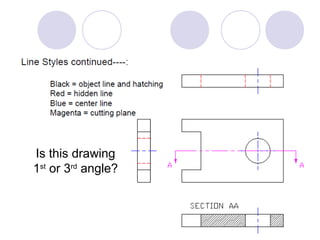


The document discusses various types of engineering drawings including isometric drawings, which show a three-dimensional view of a component or assembly from three surfaces in one view. It also covers orthographic projections, which use front, top, side, and other views to represent a three-dimensional object in two dimensions. The document explains techniques for drawing boxes, more complex shapes, threaded parts, and using section views to show hidden details. It also discusses dimensions, title blocks, line types, and other aspects of creating technical drawings.


