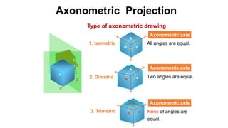
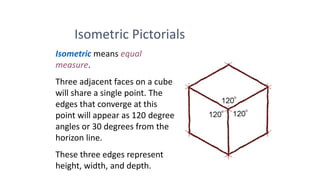
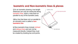
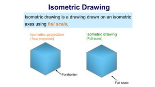
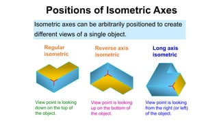
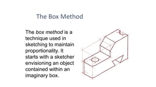
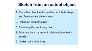
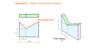
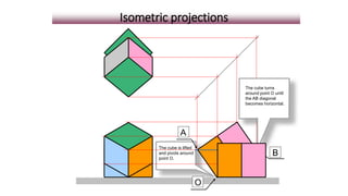
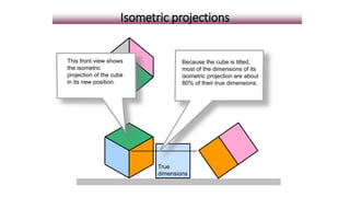
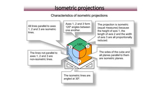
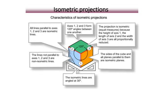
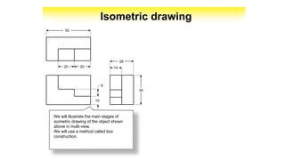
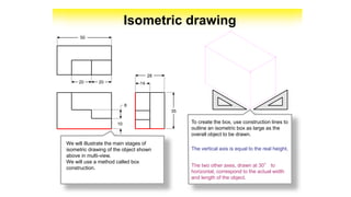
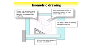
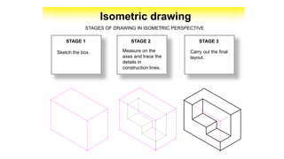
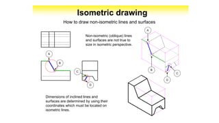
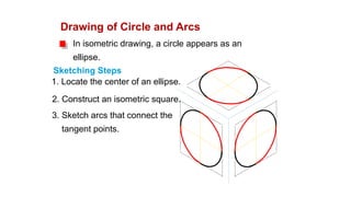
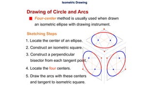
Isometric Projection
& Isometric drawing
Axonometric Projection
Type of axonometric drawing
a
b c2. Dimetric Two angles are equal.
b
a
c3. Trimetric None of angles are
equal.
a
b c
1. Isometric All angles are equal.
A
B
C
DA
B
C
D
Axonometric axis
Axonometric axis
Axonometric axis
Oblique Projection
A
D
C
B
B
C D
A
Oblique drawing angle
30o
45o 60o
Type of Oblique drawing
45o 45o
1) Cavalier 2) Cabinet
Full
scale Half
scale
Isometric means equal
measure.
Three adjacent faces on a cube
will share a single point. The
edges that converge at this
point will appear as 120 degree
angles or 30 degrees from the
horizon line.
These three edges represent
height, width, and depth.
Isometric Pictorials
ISOMETRIC DRAWINGS
•The object is held with one vertical edge,
then tilted toward the viewer until the
other horizontal edge are at a 30 degree
angles.
•All three axes are scaled equally at 120
degrees.
•Since all lines are parallel, isometric
drawings can be created quickly.
Isometric and Non-isometric lines & planes
 In an isometric drawing, true length
distances can only be measured along
isometric lines, that is, lines that run
parallel to any of the isometric axes.
Any line that does not run parallel to
an isometric axis is called a non-
isometric line
 Non-isometric lines include inclined
and oblique lines and can not be
measured directly. Instead they must
be created by locating two end points.
Isometric Drawing
Isometric drawing is a drawing drawn on an isometric
axes using full scale.
Isometric projection
(True projection)
Isometric drawing
(Full scale)
Forshorten
Full scale
Positions of Isometric Axes
Isometric axes can be arbitrarily positioned to create
different views of a single object.
Regular
isometric
Reverse axis
isometric
Long axis
isometric
View point is looking
down on the top of
the object.
View point is looking
up on the bottom of
the object.
View point is looking
from the right (or left)
of the object.
The Box Method
The box method is a
technique used in
sketching to maintain
proportionality. It
starts with a sketcher
envisioning an object
contained within an
imaginary box.
Good sketching
requires a sense of
proportion, and the
ability to estimate
size, distance,
angles, and other
spatial relationships.
Proportion and Estimation
good sketch
poor sketch
2. Define an isometric axis.
3. Sketching the enclosing box.
4. Estimate the size an and relationship of each
details.
5. Darken all visible lines.
1. Place the object in the position which its shape
and features are clearly seen.
Sketch from an actual object
1. Positioning object.
2. Select isometric axis.
3. Sketch enclosing
box.
4. Add details.
Note In isometric sketch/drawing), hidden lines are omitted
unless they are absolutely necessary to completely
describe the object.
Sketch from an actual object
STEPS
5. Darken visible lines.
Front View
Top View
Side View
Example 1 : Object has only normal surfaces
Bottom View
Bottom
Front
Side
Side
Front
Top
Regular
Reverse
W
D
H
H
DW
Example 2 : Object has inclined surfaces
W HD
y
x Front View
y
x
Nonisometric line
The cube is lifted
and pivots around
point O.
Isometric projections
The cube turns
around point O until
the AB diagonal
becomes horizontal.
O
A
B
Isometric projections
This front view shows
the isometric
projection of the cube
in its new position.
True
dimensions
Because the cube is tilted,
most of the dimensions of its
isometric projection are about
80% of their true dimensions.
Isometric projections
This front view shows
the isometric
projection of the cube
in its new position.
True
dimensions
Because the cube is tilted,
most of the dimensions of its
isometric projection are about
80% of their true dimensions.
Isometric projections
All lines parallel to axes
1, 2 and 3 are isometric
lines.
2 3
1
120º
The isometric lines are
angled at 30º.
The lines not parallel to
axes 1, 2 and 3 are
non-isometric lines.
The sides of the cube and
all planes parallel to them
are isometric planes.
Axes 1, 2 and 3 form
120º angles between
one another.
The projection is isometric
(equal measures) because
the height of axis 1, the
length of axis 2 and the width
of axis 3 are all proportionally
reduced.
Characteristics of isometric projections
Isometric projections
Isometric drawing
2020
50
10
8
14
28
35
We will illustrate the main stages of
isometric drawing of the object shown
above in multi-view.
We will use a method called box
construction.
2020
50
10
8
14
28
35
We will illustrate the main stages of
isometric drawing of the object shown
above in multi-view.
We will use a method called box
construction.
To create the box, use construction lines to
outline an isometric box as large as the
overall object to be drawn.
The vertical axis is equal to the real height.
The two other axes, drawn at 30° to
horizontal, correspond to the actual width
and length of the object.
Isometric drawing
2020
50
10
8
14
28
35
We will illustrate the main stages of
isometric drawing of the object shown
above in multi-view.
We will use a method called box
construction.
To create the box, use construction lines to
outline an isometric box as large as the
overall object to be drawn.
The vertical axis is equal to the real height.
The two other axes, drawn at 30° to
horizontal, correspond to the actual width
and length of the object.
Isometric drawing
Isometric drawing
The object is drawn by removing
volumes from the box.
A 30º- 60º set square is used to
trace the isometric lines.
The box is an isometric drawing
as large as the overall object to
be shown. Its lines are drawn
very faintly.
Measurements are reported on
the isometric axes, or on lines
parallel to these axes.
Isometric drawing
STAGE 1 STAGE 2 STAGE 3
Sketch the box.
STAGES OF DRAWING IN ISOMETRIC PERSPECTIVE
Measure on the
axes and trace the
details in
construction lines.
Carry out the final
layout.
Isometric drawing
STAGE 1 STAGE 2 STAGE 3
Sketch the box.
STAGES OF DRAWING IN ISOMETRIC PERSPECTIVE
Measure on the
axes and trace the
details in
construction lines.
Carry out the final
layout.
Non-isometric (oblique) lines
and surfaces are not true to
size in isometric perspective.
Isometric drawing
How to draw non-isometric lines and surfaces
Dimensions of inclined lines and
surfaces are determined by using their
coordinates which must be located on
isometric lines.
A
B
D
C
C
D
A
B
Isometric drawing
Non-isometric (oblique) lines
and surfaces are not true to
size in isometric perspective.
How to draw non-isometric lines and surfaces
Dimensions of inclined lines and
surfaces are determined by using their
coordinates which must be located on
isometric lines.
A
B
D
C
C
D
A
B
Drawing of Circle and Arcs
In isometric drawing, a circle appears as an
ellipse.
2. Construct an isometric square.
3. Sketch arcs that connect the
tangent points.
Sketching Steps
1. Locate the center of an ellipse.
Isometric Drawing
Drawing of Circle and Arcs
3. Construct a perpendicular
bisector from each tangent point.
4. Locate the four centers.
5. Draw the arcs with these centers
and tangent to isometric square.
Sketching Steps
Four-center method is usually used when drawn
an isometric ellipse with drawing instrument.
2. Construct an isometric square.
1. Locate the center of an ellipse.
References
• Material developed by Project Lead the Way
• akademi.itu.edu.tr/ozkirimmu/DosyaGetir/56755/Chapter%2005%2
0Pictorial%20sketching.ppt
• cdpsciencetechno.org/cdp/UserFiles/File/telechargement/isometric
_drawings.ppt
• www.cs.unca.edu/~bruce/Fall07/179/isometricSketches.ppt
• www.augusta.k12.va.us/cms/lib01/VA01000173/Centricity/ModuleI
nstance/6006/How_to_make_an_Isometric_Drawing.ppt

lecture engnering drawing

  • 1.
  • 2.
    Axonometric Projection Type ofaxonometric drawing a b c2. Dimetric Two angles are equal. b a c3. Trimetric None of angles are equal. a b c 1. Isometric All angles are equal. A B C DA B C D Axonometric axis Axonometric axis Axonometric axis
  • 3.
    Oblique Projection A D C B B C D A Obliquedrawing angle 30o 45o 60o Type of Oblique drawing 45o 45o 1) Cavalier 2) Cabinet Full scale Half scale
  • 4.
    Isometric means equal measure. Threeadjacent faces on a cube will share a single point. The edges that converge at this point will appear as 120 degree angles or 30 degrees from the horizon line. These three edges represent height, width, and depth. Isometric Pictorials
  • 5.
    ISOMETRIC DRAWINGS •The objectis held with one vertical edge, then tilted toward the viewer until the other horizontal edge are at a 30 degree angles. •All three axes are scaled equally at 120 degrees. •Since all lines are parallel, isometric drawings can be created quickly.
  • 6.
    Isometric and Non-isometriclines & planes  In an isometric drawing, true length distances can only be measured along isometric lines, that is, lines that run parallel to any of the isometric axes. Any line that does not run parallel to an isometric axis is called a non- isometric line  Non-isometric lines include inclined and oblique lines and can not be measured directly. Instead they must be created by locating two end points.
  • 7.
    Isometric Drawing Isometric drawingis a drawing drawn on an isometric axes using full scale. Isometric projection (True projection) Isometric drawing (Full scale) Forshorten Full scale
  • 8.
    Positions of IsometricAxes Isometric axes can be arbitrarily positioned to create different views of a single object. Regular isometric Reverse axis isometric Long axis isometric View point is looking down on the top of the object. View point is looking up on the bottom of the object. View point is looking from the right (or left) of the object.
  • 9.
    The Box Method Thebox method is a technique used in sketching to maintain proportionality. It starts with a sketcher envisioning an object contained within an imaginary box.
  • 10.
    Good sketching requires asense of proportion, and the ability to estimate size, distance, angles, and other spatial relationships. Proportion and Estimation good sketch poor sketch
  • 11.
    2. Define anisometric axis. 3. Sketching the enclosing box. 4. Estimate the size an and relationship of each details. 5. Darken all visible lines. 1. Place the object in the position which its shape and features are clearly seen. Sketch from an actual object
  • 12.
    1. Positioning object. 2.Select isometric axis. 3. Sketch enclosing box. 4. Add details. Note In isometric sketch/drawing), hidden lines are omitted unless they are absolutely necessary to completely describe the object. Sketch from an actual object STEPS 5. Darken visible lines.
  • 13.
    Front View Top View SideView Example 1 : Object has only normal surfaces Bottom View Bottom Front Side Side Front Top Regular Reverse W D H H DW
  • 14.
    Example 2 :Object has inclined surfaces W HD y x Front View y x Nonisometric line
  • 15.
    The cube islifted and pivots around point O. Isometric projections The cube turns around point O until the AB diagonal becomes horizontal. O A B
  • 16.
    Isometric projections This frontview shows the isometric projection of the cube in its new position. True dimensions Because the cube is tilted, most of the dimensions of its isometric projection are about 80% of their true dimensions.
  • 17.
    Isometric projections This frontview shows the isometric projection of the cube in its new position. True dimensions Because the cube is tilted, most of the dimensions of its isometric projection are about 80% of their true dimensions.
  • 18.
    Isometric projections All linesparallel to axes 1, 2 and 3 are isometric lines. 2 3 1 120º The isometric lines are angled at 30º. The lines not parallel to axes 1, 2 and 3 are non-isometric lines. The sides of the cube and all planes parallel to them are isometric planes. Axes 1, 2 and 3 form 120º angles between one another. The projection is isometric (equal measures) because the height of axis 1, the length of axis 2 and the width of axis 3 are all proportionally reduced. Characteristics of isometric projections
  • 19.
    All lines parallelto axes 1, 2 and 3 are isometric lines. 2 3 1 120º The isometric lines are angled at 30º. The lines not parallel to axes 1, 2 and 3 are non-isometric lines. The sides of the cube and all planes parallel to them are isometric planes. Axes 1, 2 and 3 form 120º angles between one another. The projection is isometric (equal measures) because the height of axis 1, the length of axis 2 and the width of axis 3 are all proportionally reduced. Characteristics of isometric projections Isometric projections
  • 20.
    Isometric drawing 2020 50 10 8 14 28 35 We willillustrate the main stages of isometric drawing of the object shown above in multi-view. We will use a method called box construction.
  • 21.
    2020 50 10 8 14 28 35 We will illustratethe main stages of isometric drawing of the object shown above in multi-view. We will use a method called box construction. To create the box, use construction lines to outline an isometric box as large as the overall object to be drawn. The vertical axis is equal to the real height. The two other axes, drawn at 30° to horizontal, correspond to the actual width and length of the object. Isometric drawing
  • 22.
    2020 50 10 8 14 28 35 We will illustratethe main stages of isometric drawing of the object shown above in multi-view. We will use a method called box construction. To create the box, use construction lines to outline an isometric box as large as the overall object to be drawn. The vertical axis is equal to the real height. The two other axes, drawn at 30° to horizontal, correspond to the actual width and length of the object. Isometric drawing
  • 23.
    Isometric drawing The objectis drawn by removing volumes from the box. A 30º- 60º set square is used to trace the isometric lines. The box is an isometric drawing as large as the overall object to be shown. Its lines are drawn very faintly. Measurements are reported on the isometric axes, or on lines parallel to these axes.
  • 24.
    Isometric drawing The objectis drawn by removing volumes from the box. A 30º- 60º set square is used to trace the isometric lines. The box is an isometric drawing as large as the overall object to be shown. Its lines are drawn very faintly. Measurements are reported on the isometric axes, or on lines parallel to these axes.
  • 25.
    Isometric drawing STAGE 1STAGE 2 STAGE 3 Sketch the box. STAGES OF DRAWING IN ISOMETRIC PERSPECTIVE Measure on the axes and trace the details in construction lines. Carry out the final layout.
  • 26.
    Isometric drawing STAGE 1STAGE 2 STAGE 3 Sketch the box. STAGES OF DRAWING IN ISOMETRIC PERSPECTIVE Measure on the axes and trace the details in construction lines. Carry out the final layout.
  • 27.
    Non-isometric (oblique) lines andsurfaces are not true to size in isometric perspective. Isometric drawing How to draw non-isometric lines and surfaces Dimensions of inclined lines and surfaces are determined by using their coordinates which must be located on isometric lines. A B D C C D A B
  • 28.
    Isometric drawing Non-isometric (oblique)lines and surfaces are not true to size in isometric perspective. How to draw non-isometric lines and surfaces Dimensions of inclined lines and surfaces are determined by using their coordinates which must be located on isometric lines. A B D C C D A B
  • 29.
    Drawing of Circleand Arcs In isometric drawing, a circle appears as an ellipse. 2. Construct an isometric square. 3. Sketch arcs that connect the tangent points. Sketching Steps 1. Locate the center of an ellipse.
  • 30.
    Isometric Drawing Drawing ofCircle and Arcs 3. Construct a perpendicular bisector from each tangent point. 4. Locate the four centers. 5. Draw the arcs with these centers and tangent to isometric square. Sketching Steps Four-center method is usually used when drawn an isometric ellipse with drawing instrument. 2. Construct an isometric square. 1. Locate the center of an ellipse.
  • 31.
    References • Material developedby Project Lead the Way • akademi.itu.edu.tr/ozkirimmu/DosyaGetir/56755/Chapter%2005%2 0Pictorial%20sketching.ppt • cdpsciencetechno.org/cdp/UserFiles/File/telechargement/isometric _drawings.ppt • www.cs.unca.edu/~bruce/Fall07/179/isometricSketches.ppt • www.augusta.k12.va.us/cms/lib01/VA01000173/Centricity/ModuleI nstance/6006/How_to_make_an_Isometric_Drawing.ppt