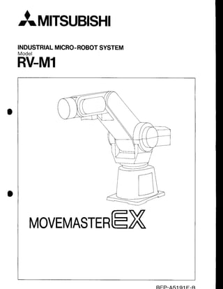
SlideShare a Scribd company logo
1 of 252
Download to read offline
a
AMrsuBtsHl
INDUSTRIAL
MICRO-
ROBOT
SYSTEM
Model
RV-M1
MOVEMASTERtrX
I
f sercrrrcnrrorus
THIS MANUAL IS DIVIDEDUP AS FOLLOWS
Givesoverallof construction,
mainspecifications,
usinginstruc-
tions.etc. Please
readthis oart first.
Givesinstallation
and connection
procedures,
basicfunctions
of
systemcomponents,
powering-up
to position
settingprocedures,
and programgeneration
and execution
procedures.
p oernarroru
13I DESCRIPTION
OF THECOMMANDS
Givesformatsand usagesof intelligent
commands
which have
been classified
in accordance
with functions.The commands
appearin alphabetical
order.
I4 MAINTENANCE
AND INSPECTION
@ neeeNorcrs
Givesmaintenance,
inspection,
partsreplacement
procedures
and
servrcepans.
Gives interfacing
with a personalcomputerand externall/O
equipment,
cartesian
coordinate
systemreference
positionset-
ting, commandlist,application
programs,
etc.
CONTENTS
I 1 I SPECIFICATIONS
1,UNPACKING
ANDACCEPTANCE
INSPECTION
2.SYSTEM
OFCONSTRUCTTON
2.1 Overall
of Construction
2.2 Standard
andOptional
1.1 Unpack
ingInstructions
1.2 Acceptancelnspection
' ' t - 5
1-3
1-5
J . I
3.1.3 Externaldimensions . . . . . . 1 - 7
' ' ' ' ' ' t - l t
3.1
.4 Operation
space
. .......... .
3.1.5 Basic
operations.
.. .......- ' " ' . ' .. . . . .
. . . . . . . .
. . . . . .
1 - 9
J . Z DriveUnit .......-.
1_'t'l
3.2.1 Nomenclature. .. . . . .
. . . . .
. . . . . .
1 - 1
1
3.2.3 Exte
rna
I dimensions
3.3 Teaching
Box(Option)
3.3.1 Nomenclature..
3.3.2 Externaldimensions ...........
1-15
3.4 Motor-operated
Hand(Option).. ...........................
1-16
4.USINGINSTRUCTIONS
t - t J
1-14
1-'t4
4.1
A '
4.3
4.4
A F
4.6
4.7
1-17
1-17
1-17
1 - 1 8
1 - 1 8
1 - 1 9
1 - 1 9
Line
Voltage
.. .....
5.WARRANTY
PERIOD
ANDPAINTCOLORS
1 .
iz] onennrom
1.'l Transportation
of the Robot " " 2-1
1.2 lnstallation
of theRobot 2-3
'l.3
Transportation
and Installation
of the DriveUnit. .. ........... . . . . 2-5
1 . 4 l n s t a l l a t i o n o f
t h el / OC a r d . . . . . . . . . . . . . . . . . . . '
. . . . . . 2 - 5
1.5 Grounding 2-6
1.6 CableConnections 2-7
1 . 7 l n s t a l l a t i o n
o f t h eH a n d( O p t i o n ) .
. . . . . . . . . . . . . . . . . . 2 - 8
'1.8
Installation
of theTeaching
8ox (Option) " " " '2-10
1.9 lnstallation
of the Backup
Battery
{Option) .. .. .. . . 2-10
1.10 instailatron
of the Emergency
StopSwitch " '2-11
D r i v e
Un i t . . . . . . . . ' . ' .
2 - 1 2
2.1.1 Functionsoffrontcontrol
switches
and LEDs" ' " " "'2-12
2.1.2 Functionsof sidesettingswitchesand LEDs " " " ' 2-13
2.1.3 Functionsof connectors,
switches,and terminalblockon rearpanel " " """ 2-16
T e a c h i n g
B o x " . " " " " 2 - 1 8
2 . 2 . 1 F u n c t i o n s o f
t h es w i t c h e s " " " " " " " " 2 - 1 8
2 , 2 . 2 F u n c t i o n s o f e a c h k e y " " " " " " " " 2 - 1 8
2.2.3 Functionsofthe
indicator
LED " "" " " "" " "" '2-21
2.2.4 Eeleasing
the brakes ' ' '' '' '' '' ''''''2-22
2.2.5 lrrreliigent
commandscorresponding
to eachkey" " " """"" 2-22
SystemContigu
ration "" 2-23
3.1.1 Systemconfiguration
centering
arounda personal
computer" "" """""'2-23
3.1.2 Systemconfiguration
centering
aroundthe driveunit " "" "" " """ "" " '2-24
Robot-Computer
Link 2-25
3.2.1 Cerrt
ronicsinterface 2-25
3.2.2 RS232C
interface " "'2-25
ControlModes " """ "" " " "" 2-26
3 . 3 . 1 P e r s o n a l c o m p u t e r
r h o d e" ' ' ' 2 - 2 6
3.3.2 Driveunitmode ' ' '2-24
4 . 1 S e t t i n g
t h eS i d e
S e t t i n g
S w i t c h e s " ' ' ' ' ' 2 - 2 9
4.2 Turning
Power
ON 2-29
4.3 Origin
Setting """'2-29
2.2
J . l
3.2
3.3
5. POSITION
SETTING
PROCEDURE
5.1 Setting
theCartesian
Coordinate
System
Reference
Position
'. ............
..................
2-30
5 . 2 S e t t i n g t h e T o o l
L e n g t h . . . . . . . . . . . . 2 - 3 0
5.3 Defining,Verifying,Changing,andDeletingthePositions"
"' ...'..2-31
6.
o . l
6.2 Executing
theProgram " " 2-34
6.2.1 Stepexecution
' " " " "... ...2-31
6.2.2 Starting
theprogram . .2-34
6.2.3 Stopping/resta
rting
theprogram ...............2-35
6.2.4 Stoppin
g/resetting
theprogram
7. WRITINGTHE PROGRAM/POSITION
DATA IN EPROM
( P E R S O N A L C O M P U T E R M O D E ) .
. . . . . . . . . . . .. . . . . 2 - 3 6
7.1 Inserting
Erased
EPROM .'. .....'.....2-36
7.2 Writing
Data
intoEPROM ....... .....2-36
7.3 Preca
utionsforStorag
e of EPROM "" "" " "" " " 2-36
8.1 lnserting
theEPROM ' 2-37
8.2 Setting
theSideSetting
Switches
.......... . . . . .. . 2-37
8.3 TurningPower
ON ' ' 2-37
8.4 Executing
theProgram ' ' 2-37
8.4.1 Stepexecution ' 2-37
8.4.2 Starting
theprogram """ " 2-37
8.4.3 Stopping/resta
rtingtheprogram " " "" " " 2-38
8.4.4 Stopping/resetting
theprogram 2-38
9. OPERATION
USINGTHEEXTERNAL
SIGNALS
8.
10.
1 0 . 1E r r o r M o d e
I " " " " " " " " 2 - 4 O
10.2 ErrorModeII " 2-41
El DESCBTPTTON
OF THE COMMANDS
1 .
2 . 1 P o s i t i o n / M o t i o n
C o n t r o l
I n s t r u c t i o n s . . . .
. . . . . .. . . . . . . . ' . ' . .
. . . . . . . . . . . . . .
3 - 3
DP{Decrement
Position) " Moving
to a position
number
onesma1|er................
... . 3-3
DW(Draw) 'Moving a distance
specified
in the cartesian
coordinate
s y s t e m . . . . . . . . . . . 3 - 4
HE(Here) Teaching
thecurrent
position .............
. 3-5
HO{Home) " Settingthe cartesian
coordinate
systemreference
posi-
t i o n . . . . ' . . . . . . . . . . . . . . 3 - 6
l P( l n c r e m e n t
P o s i t i o n )
. . . . M o v i n g t o a p o s i t i o n n u m b e r o n e g r e a t e r . . . . . . . . . . . . . . . . . . . 3 - 7
MA (Move
Approach) Moving
to a specified
incremental
dimension
...............
3-8
MC{Move
Continuous)
" " Moving
through
intermediate
points
continuously....
.....3-9
M J ( M o v e J o i n t ) " " . ' . . T u r n i n g
e a c h
j o i n t a s p e c i f i e d a n g l e . . . . . . . . . . . . . . . . . . . . . . . . . . . 3 - 1 1
MO(Move) Movingto a specified
position
by articulated
interpola-
t i o n " . . . . . .
. . 3 - 1 2
MP(MovePosition) Movingto a position
whosecoordinates
arespecified...
3-13
MS(Move
Straight) Movingto
a specified
position
bylinear
interpolation....
3-'14
MT(MoveTool) Movingan incremental
distance
specified
in the tool
d i r e c t i o n " " " " " " ' 3 - 1 6
N T( N e s t ) . R e t u r n i n g t h e r o b o t t o o r i g i n . . . . . . . . ' . . ' . . . . . . . ' . . . ' . ' . . . ' . . . 3 - 1 7
OG(Origin) Movingto the cartesian
coordinate
systemreference
positlon " " "" 3-18
PA(Pallet
Assign) ' ..Defining
thenumberofcolumnandrowgridpoints
for a
s p e c i f i e d
o a l l e t ' . . . . . . . . . . . . . . . ' . .
3 - 1 9
PC(Position
Clear)" " Clearing
a specified
position " "' 3-20
PD(Position
Define) " Defining
thecoordinates
ofaspecifiedposition..........3-21
PL(Position
Load) " Asslgning
the positiondataof a specified
positionto
another
specified
position """ " " "' 3-22
PT(Pallet) Calculating
thecoordinates
of a gridpointon a specified
n a | | e t .
. . . . . . . . . . . . . . . . . 3 - 2 3
PX(Position
Exchange)" Exchanging
the coordinates
of a positionfor thoseof
another" "" " " "" 3-2'l
SF(Shift)" Shifting
thecoordinates
of a specified
position" " " 3-28
SP{Speed) Settingthe operating
velocityand acceleration/decel-
eration
time" " "" 3-29
Tl{Timer) " Halting
themotionfor a specified
periodoftime " 3-30
T L ( T o o l ) " S e t t i n g
t h e t o o l
l e n g t h . . . . ' . . . . " " " ' 3 - 3 1
Program
Control
lnstructions
" " ' """""'3-32
CP(Compare
Counter)
"" Loading
counter
dataintothecomparison
register
"" " 3-32
DA(Disable
Act) Disabling
theinterrupt
byanexternalsignal
"" "" " " 3-33
DC(Decrement
Counter) " Subtracting
1froma valuein a specified
counter
"" " 3-34
D L ( D e l e t e L i n e )
" " " " D e l e t i n g
a s p e c i f i e d
p a r t
o fa p r o g r a m " " " " " " ' 3 - 3 5
z . z
EA{Enable
Act) Enabling
theinterrupt
by anexternal
signal "" " "'
ED(End) " Ending
theprogram
EO(lfEqual) Causing
a jumpto occurif thecontents
of thecompari-
sonregister
equala specified
value " " "" " "" '
GS(GoSub) Executing
a specified
subroutine '
GT(GoTo) Causing
alumptooccurto
a specified
linenumber""'
lC(lncrement
Counter) " 'Adding1to thevalueina specified
counter"" "" " '
LG(lfLarger)
.".................
Causing
a jumpto occurif thecontents
of thecompari-
sonregister
aregreater
thana specified
value"" " " " 3-43
NEllf NotEqual) " " " Causing
a jump to occurif thecontents
of thecompari-
sonregister
do notequalaspecified
value " "" " " 3-44
NW(New) ..Deleting
allprograms
andposition
data" "" " ' 3-45
NX(Next)" " " " "" " 'Specifying
therangeof
a loopina program
" "" " ""'3-46
RC(Repeat
Cycle)' ' ' 'Specifyingthenumberof
repeated
cycles
ofa loop""'3-47
RN{Run) " "' Executing
a specified
partof prog
ram "" """""" 3-48
RT(Return)" Returningto the main program after completinga
s u b r o u t i n e " " " " " 3 - 4 9
S C ( S e t C o u n t e r )
" " ' ' ' L o a d i n g a v a l u e i n a s p e c i f i e d c o u n t e r " "
" " " " " " ' 3 - 5 0
SM(lfSmaller)" Causing
a jumpto occurif thecontents
of thecompari-
sonregister
aresmaller
thana specified
value" " " " ' 3-5i
Hand
Control
Instructions"
'. " "'3-52
GC(GripClose)
" " " " "'Closingthehandgrip "" " " "" " "" 3-52
GF(Grip
Flag)
'. ........... '. Defining
theopen/close
state
ofthehand "" " " " 3-53
G O( G r i p
O p e n )
" " " " " O p e n i n g t h e
h a n d
g r i p " " " " " " 3 - 5 4
GP(GripPressure)"
" "" " Definingthe grippingforce/timewhen the hand is
3-36
3-38
3-39
3-40
3-41
3-42
3-55
3-56
3-56
3-57
3-58
3-59
3-60
2.3
2.4
2 . 5
lD(lnput
Direct)" "" " Fetching
anexternalsignal
" " " '
lN(lnput) " Fetching
anexternalsignal
synchronously
" "" " " '
OB(OutputBit)
"" "" " " " Setting
theoutput
state
ofa specif
iedbit " "" " " "'
OD(Output
Direct)..""" " 'Outputting
specified
data " "" " "
O T ( O u t p u t )
" " " " " " ' O u t p u t t i n g
s p e c i f i e d
d a t a
s y n c h r o n o u s l y
" " " " " '
TB(Test
Bit)" " " " " "'Causinga jumpto occurdepending
on thecondition
of
a specified
external
signalbit" " "" " " "" "" " " 3-6'
RS232C
Readlnstructions " 3-62
CR(Counter
Read)"" ' Reading
thedataina specified
counter"" " " " 3-62
DR(Data
Read)"" " " " Reading
thedataintheexternal
inputport " "" ' 3-63
E R ( E r r o r R e a d )
. " " " " R e a d i n g t h e s t a t u s o f t h e
e r r o r
" " " " " " ' 3 - 6 4
LR(LineRead) Reading
theprogram
on a specified
linenumber" " " 3-65
PR(Position
Read)"- " " Reading
thecoord
inates
of a specified
position " "'3-67
WH(Where) Reading
thecoordinates
ofthecurrent
position " ' 3-68
Miscellaneous " "'3-69
RS(Reset)
TR(Transfer)
" " " Transferring
EPROM
data
to RAM "" ""'3-70
wR (write) writingRAMdataintoEPROM """""" 3-7
' ( C o m m e n t )
" " " " ' W r i t i n g
a c o m m e n t" " " ' 3 - 7 2
2.6
l!l MATNTENANCE
AND TNSPECTTON
3.
2 . 1
2.2
2.3
J . I
3.2
3.5
J . O
A 1
4.2
4.3
Construction
ofthe Robot.... ..........4-g
R e m o v a l
o f t h eC o v e r s . . . . . . . . . . . . . . . . . .
4 - 1 0
R e p l a c e m e n t
o f t h eM o t o rB r u s n. . . . . . . . . . . . . . . . . . . - . . - . . 4 - j 2
3.3.1Checking
and replacing
thewaistdrivemotorbrushes.. ..........4-12
3.3.2Checking
and replacing
the shoulder/elbow
drivemotorbrushes....................
4-15
3.3.3Replacing
the wristpitchdrivemotor...... ...... ......................
4-16
3 . 3 . 4R e p l a c i n g t h e w r i s t r o l l d r i v e m o t o r . . . . . . . . . . . . . ........................ 4 -1g
Adjustment
and Replacement
of theTimingBelt......'....
..... ...........
4-20
3.4.1 Replacement
frequency... .....4-20
3 . 4 . 2C h e c k i n g , a d j u s t i n g , a n d r e p l a c i n g t h e s h o u l d e r d r i v e t i m i n g b e l t . . . . . . . . . . . . . . . . . . 4 - 2 1
3.4.3Checking,
adjusting,
andreplacing
the elbowdrivetimingbe1t........
... .. ......4-24
3.4.4Checking,
adjusting,
andreplacing
thewristpitchdrivetimingbelt..................
4-27
Replacement
ofthe CurledCaores............ ............
4-30
lnspection,
Adjustment,
and Replacement
ofthe Brakes......... .........
4-32
3.6.1Checking,
ad.justing,
and replacing
theshoulder
brake...............
...................
4-32
3.6.2Checking,adjusting,andreplacingtheelbowbrake... ... ....4-34
.. 4-36
3.4
4.
@ neeeruorces
1 . 1
1 . 2
1 . 4
1 . 5
2.
1 1
2.2
2 . 5
APP-1
APP.5
3 . 1 . A
3 . 1
. 8
3.2.8
5 . 5 . 4
3.3.8
3.4.A
3.4.8
3.5
F u n c t i o n
o f E a c h
S i g n a l
L i n e . . .
. . . . . . . . . . . . .
RS232C
Settings
2.5 RS232C
Cable..
2.6 RS232C
Interfacing
Examples
J . O
a ' 7
External
l/OConnector
PinAsslgnments
lType
A l/OCard)..................................App-15
External
l/OConnector
PinAssignments
(Type
B l/OCard)
...'..............................App-16
l / O C i r c u i t S p e c i f i c a t i o n s ( T y p e A l / O C a r d ) . . . . . . . . . . . . . . . . . . . . . . . . ' . . . . . A p p - l 7
l/OCircuit
Specifications
(Type
B l/OCard).
. .......... ..................App-18
Functionsof
l/OSignal
Lines
(Type
A l/OCard)
............ . ...........App-19
Functions
of l/OSignal
Lines
(Type
B l/OCard)
.......
.. . . .............App-20
E x a m p l e o f
C o n n e c t i o n t o l / O C i r c u i t s ( T y p e A l / O C a r d ) . . . . . . . .
. . . . . . . . . ' . . . . . . . . . . . . . . . . A p p - 2 1
E x a m p l e
o fC o n n e c t i o n t o l / O C i r c u i t s ( T y p e B l / O C a r d ) . . . . . . . . . . . . . . . . . . . . . . . . . . . . . . . . . . . . . A p p - 2
l/OSignal
Line
Timing
Chart
(Synchronous
l/O)......... . ............App-23
3 . 5 . 1 . A S y n c h r o n o u s i n p u t t i m i n g ( T y p e A l / O c a r d ) . . . . . . . . . . . . . . . . . . A p p - 2 3
3.5.'l.B
Synchronous
inputtiming
(Type
B l/Ocard).........
. .........App-23
3.5.2.A
Synchronousoutputtiming(TypeAl/Ocard)................ ..App-24
3 . 5 . 2 . 8
S y n c h r o n o u s o u t p u t t i m i n g ( T y p e B l / O c a r d ) . . . . . . . . . . . . . . A p p - 2 4
3.5.3.A
Dedicated
l/Otiming(Type
A t/Ocard)................ ............App-25
3.5.3.8Dedicated
l/OtiminglTypeB l/Ocard) .....App-26
External
l/OCab1e.....
... .....'....APP-27
Precautio
nsforCon
nection
to ExternaI
Equipment ....................APP-28
4. CARTESIAN
COORDINATE
SYSTEM
REFERENCE
4.1 Movingthe
Robotto
Beference
Position....
.. ... ..App-29
4.2 Setting
theReference
Position
..... .... ..............
App-29
4.3 StoringReference
Position
Datain EPROM .........App-30
4.4 Loadingthe
Reference
Position
Data...'......
.. . ..APp-31
5. PROGRAMMING
SYSTEM
USING
PERSONALCOMPUTER ..."".......APP-32
5. SAMPLE
PROGRAMS.... ...............App-36
7 . C O M M A N D 1 | S T . . . . . . .
. . . . . . . . . . . . . . . . . A p p - 4 4
8. TIM|NG
BELTTENSTON .......
.....'..
App-48
9 . D E F I N I T I O N O F W E I G H T C A P A C | T Y . . . . . . . . . . . . . . . . . . . . . A p p - 4 9
10.ROBOTARMSTORAGEPOS|T|ON...
........... .....App-50
11.OPERAT|ONALSPACED|AGRAM.
.............. .......App-51
1 2 .W | R | N G D I A G R A M . . . . . . . . . . . . . . . . . .
. . A p p - 5 2
1 3 .D R | V E U N | T W t R t N G D | A G R A M . . . . . . . . . . . . . . . . . . . ' . . . . . . A p p - 5 4
1.SPEC|F|CATI0N
2.OPERATIOl{
3.DESCRIPTION
OT
TIIICOt|MANDS
4. MAIl{TEI{ANCT
A1{D
INSPECTION
5.APPENDICTS
CONTENTS
(SPECIFICATIONS}
1.UNPACKING
ANDACCEPTANCE
INSPECTION
1.1 Unpacking
Instructions ' ' '' 1-1
1.2 Acceptance
Inspection
" """ "'1-2
2.SYSTEM
OFCONSTRUCTION
2. 1 Overall
ofConstruction
" " ""'
Standardand OptionalEquipment " " " ....'t-4
R o b o t
" " " " " " " " " " ' 1 - 5
3.1.1 Nomenclature
' " " "" 1-5
3.1.2 Standard
specifications
' "" """ "" 1-7
3.1.3 Externaldimensions """' " "1-7
3 . 1 . 4O p e r a t i o n s p a c e
" " ' " " " " " " ' 1 - 8
3 . 1 . 5B a s i c
o p e r a t i o n s "
" " " " " " " " " " " 1 - 9
3.1.6 Origin
set(Return
to origin) "" " " ' " "" 1-10
Drive
Unit
"" "" " 1-11
3.2.1 Nomenclature" "" "" " "' 1-11
3 . 2 . 2 S t a n d a r d
s p e c i f i c a t i o n s
' " " " " " " " ' ' l - 1 2
t - J
1-5
3 . 1
3.2
3.4
4.1
.+.J
4.4
1+.3
1 - 1 3
1-14
1-14
1 - 1
5
1 - 1
6
1-17
1-17
1-'t7
1 -
1 8
1 - 1 8
1 - 1 9
1 - 1 9
3.2.3 Externaldimensions
Teaching
Box(Option)
3.3.1 Nomenclature
'
3.3.2 Exte
rnaldimensions
Robot ""'
4.6 Noise"'
4.7 Position
5.WARRANTY
PERIOD
ANDPAINTCOLORS
.....
3 . 1
5.2
1-21
1-21
1.SPECIFICATIONS
1. UNPACKINGAND
ACCEPTANCE
INSPECTION
1.1 Unpacking
Instructions11)Carefullyread "Section1.1 RobotTransportation,
Vol. 2,,
beforeremovingthe robotfrom the package.
(2) Donotholdthecover
(area
A in Fig.1.1.1.)
whenremoving
the
robot.
(3) The origin limit switchesand dogs (areasB, C) have been
factory-adjusted.
Do not touchthem to ensurehigh repeata-
bility.
(4) Brakeis beingappliedto the arms(areasD. E) Do not force
thesearms to extend.
(5) Do not removethe arrnfixing plate(areaF) untilthe robot
installation
is complete,
This plateprotects
the arm during
transportation.
The arm fixingplatemust be reinstalled
beforetransporting
the robot.
Do nol force the arm.
Do not force the arm,
'Do not ho d tlie cover,
Do
t h e I mil swltch.
Do not louch the imlt swilch.
Robot weight: approx. 1gkg
Fig. 1.1.1 Robot Attitude in the Package
1.SPECTF|CAT|ONS
1.2 Acceptance
Inspection Check
thatthereceived
product
conforms
to yourpurchase
order.
Ihe basiccomponents
whichvou havepurchased
areasfollows:
No. Description Tvpe Ouantity
Robot RV,Ml 1
2 Dflve unit D/U t,'11 1
3 lMolorsignai cable {5m) IVISM1 l
4 Motor power cable {5m) t,1P-
t,1
1 ,I
5 Power cord (2.5m) POW-M1 1
6 Sparefuse(10A) 1
1 Instructron
manua 1
8 Warranty card 1
I Installation
bolt M 8 x 3 0 4
1 0
Spring washer for installation
bolt
For Mg 4
1 1 Flatwasher {or installation
bolt ForM8 4
12 l/O card A 8 o r 4 1 6 ( 8 8o r 8 1 6 ) 1
Table 1.1.1 Standard Components
The following options are available.
No. Description Type
1 Teachingbox T/8,M1
2 lMotoroperated hand Htvl-01
3 EP-RO
I,4 256K,ROM
4 External l/O cable l/O-CBL{5m)
5 Personalcomputer cable NilULTl16,
PC9801 (Note)
6 Backupbattery BAT-M1
Table 1.1.2 Options
1. SPECIFICATIONS
2. SYSTEMOF
CONSTRUCTION
2.1 Overallof Construction
Motor power cable
( M P M ] ) 5 m computercable*
Motor signalcable
( M SM l ) 5 m
Drive unit
I D / UM 1 )
Robot
( R V , M 1 )
(POWM1
OPersonalcomputer
(MUtTtl6lll)
Teaching
box'
(T/BMl)
Cablelength3m
+ indicales an option.
OThe equipment indicated by should be prepared by the customer.
Fig. 1.2.1Ovelallof Construction
1.SPECIFICATIONS
2.2 Standardand
OptionalEquipment
Division Description Type Remarks
e
;
E
Robot RV-t,11
Verticalarticulatedrobot with 5 degreesof
freedom.
Drive unit D/UM1 Pobot controller.
Molor siEnalcable (5m) MS.t,4
1
Givescontrolslgnalsfrom the driveunitto
the robot.
lMotorpower cable (5m) t,1P-
M1
Suppliespower from the drive,Jnitto the
robot.
Power cord (2.5m
) POWM1 Supplies
powerto the driveunit.
l/O card A8 (or BB) to-A8 (r/o-88) 8 inputs/B
outputs.
E
c
l/O card416 (or B16i vo-A16
(t/o816) 16 lnputs/16
outpurs.
Teachingbox
{Cablelength 3m)
T/B Ml
Handy cont.ol switch box with a cable for
teach
ing, checking,correctingpositrons-
Motor operatedhand HM O1
Hand which is only used with the RV-M1
and allows16 step holdingpower control.
EP,ROM 256KROM Stores
writtenprograms
andsetpositions.
Backupbattery BATII1 Backsup l"e memory dulng power off.
External l/O cable r/o-cBL Connects
with an externalperipheral,
e.g.
programmablecontroller.
f
E
M U L T I l 6
RS'MULTI-CBL
{3m)
RS 232C cable used to connect the
MULTI'I6.
Centronics C-MU
LTI-CBL
(2m) Centronics cable used to connect the
MULr16.
PC9801
RS-232C RS'PC-CBL
(3m) RS 232C cable used to connect the
PC9801.
Centronics C-PC-CBL
(1.5m) Centronics cable used to connect the
PC9801
.
Free cable
RS-232C RSFREE
CBL(3m) RS-232Ccable wiih one free end.
Centronics C-FREE-CBL
(1.5m) Centronicscable with one {.ee end.
Table 1.2.1 Standard and Optional Equipment
Note: l/O cardA8 or 416 is for sink ioad.
B8 or 816 is for sourceload.
1. SPEC|F|CAT|ONS
3. MAIN
SPECIFICATIONS
3.1 Robot
3.1.1Nomenclature
upper arm
Elbow (J3 axis)
u"j"i:i
/A
-+f--
-t
Shoulder
(J2 axis)
Shouldercover
(upperl
Hand installation
surface
Wristpitch(J4 axis)
Waist{J1 axis) --S=:?
Curl cable
Molor siqnal cable
(to the upper
conneclorl
Motor power cable
Shoulder cover
{lower)
(to the lower
connector)
Baseside cover (R)
Forearm
* {L) Left side
Fig. 1.3.1 Nomenclature (External Viewl
1.SPECIFICATIONS
J5 axismotor
J4 axis motor
J4 axis timing belt
J2 axis timing belt
J3 axis limit switch
J2 axismotor
J4 axis limit switch
J5 axis limit switch
J2 axis brake J3 axis brake
J'l axis limit switch
Relay card
J2 axis limit switch
J1 axis motor
Fig. 1.3.2Nomenclature
(lnternalView)
1. SPECTFTCAT|ONS
3.1.2Standard
specifications
3.1.3External
dimensions
Table 3.1.1 Standard Soecifications
Itern Specifications Remarks
Mechanical Structure
5 degrees of freedom, venical articulated
robot
Operation
range
Waist rotation 300' (max. 120"/sec) J1 axis
Shoulder
rotation 130"lmax. 727sec) J2 ax;s
Elbow rotation 1'10'(max. 109'/sec) J3 axis
Wrist pitch 190" (max. 1001sec) J4 axis
ro tl 1180' (max.1637sec) J5 axis
Arm length
upper arm 250mm
Forearm 160mm
Weight capacity Max. 1.2kgf(includingthe hand weight)
75mm from the mechanical
interface (center of gravity)
Maximum path velocity 1000mm/sec (wrist tool surface) Speedat point P in Fig. 1.3.4
Positionrepeatability 0.3mm(rollcenterof the wristtool surface)
Accuracy at point P in Fig.
1.3.4
Drivesystem Electrical
servodriveusinqDCservomotors
Robot weight
Motor capacity
Approx. 1gkgf
Jl to J3 axes:30W;J4, J5 axesr1lW
Mechanical
interface
180"
Frange deraiLs lP c 968)
-
-L
?
I
I r+s
t 6 8
60
a2
254
Fig. 1.3.3 Fxternal Dimensions
1. SPECTFTCATIONS
3.1.4 Operationspace
Fig. 1.3.4OperationSpace
Note1: Theoperation
space
indicated
in Fig.1.3.4
assume
thatthe
hand is not installed
to the robot.(Traceof point P)
Note2: Thewristpitchoperation
maybe restricted
in somearea
depending
the upperarm and fore arm positions.For
details,
see Fig.5.11.1
in the appendix.
Note3: Jog operation
mustbe performed
with special
careasthe
wristmavinterfere
with the robotbaseandfloorsurface.
REMARKS
Jog operation indicatesa manual operation using the
teachingbox.
1. SPECIFICATIONS
3.1.5 Basicoperations Fig. 1.3.5showsaxis operations
in the articulated
system.
# lJ:lr 'E
Srro!de. roraro.
.rzr9
Fig. 1.3.5Operations in Articulated System
NoteI: Thepositive
direction
of the J1 andJ5 axisoperations
is
clockwise
as viewedfrom arrowsA and B, respectively.
Note2: Thepositive
direction
of theJ2,J3 andJ4 axisoperations
is the uowarddirectionof the arm and wrist.
Fig.1.3.6showsoperations
in the cartesian
coordinate
system.
_ 
, r *, l*. /f<<-=
*4)>J+; ';
-,
M/1,'y z7:-
/ - ' a
//' I roo
/ rength
/ t--
Fig. 1.3.6Operations
Note3: The TCP
system.
in CartesianCoordinateSystem
moves straightin the Cartesiancoordinate
Note4:The tool length is set by a parameter.(See the TL
command.)
Note5: f, indicates
therobotattitude
changing
operation
without
movingthe TCP.
REMARKS
Symbolsin "n" indicatethe controlkeysof the teaching
box.
1.SPECIFICATIONS
3.1.6Originset
(Returnto origin) - 1 0 "
< top vrew 2
Fig. 1.3.7RobotZeroingOperation
The robotof the Movemaster
EX RV-M1mustbe returned
to
origin after power on. (Fordetails,see Section4.3 Origin
Setting,
Vol. 2.)
The arm shouldbe movedas appropriate
by jog operation
beforereturnto originso that the robotwill not interferewith
any peripheral
equipmentduringset origin.
Returnto origin procedure
(SeeFig. 1.3.7.)
e Q.,
Note1: Allaxesinstep1),step2)mustbereturned
to originatthe
same me.
Note2: The wrist roll (J5)angleis *179.9" afteroriginset.
( 1 )
t2l
(3)
1. SPECIFICATIONS
3.2 DriveUnit
3.2.1Nomenclature
Externalvi
Frontcontrol
Ventilationopening
Side door
Powerswitch
Rating plate
Rearview (ViewA)
Centronics
connector
RS-232C
connector
Teaching box
connecror
Motor signal
cable connector
Externall/O equipmentconnector
Motor power cable connector
Heatsink
Fuse(10A)
Hand select
sw[cn
Rearterminal
block
Externalemergency
I
stop and frame
I
grouno l
@;
now
o
0
a
E
Fig. 1.3.8 Nomenclature (Drive unit)
AC inlet
1.SPECIFICATIONS
3.2.2Standard
specifications
Item Specilications
Teachingmethod
Programminq language system 163 commands), MDI'1 (using a personal
compLlter)
Control method PTP position control system usinq DC sei/o motors
Number of ccntrol axes 5 a,(es{ i l oL,!cna a^ 3l
Position detection Pulse encodei system
Return
to Origin
Originsetting Limit switcheeand pulse en.cdefs (Z phase detectionmethod)
Interpolation functioo Articulaticninterpolation,
linear interpolation
Speedsetting 'lC
stepslmax. 1000n-rmlsec)
Number of positions 629 (8KB)
Number of program sleps 2048 (16K8)
Datastorage
Write to EP ROM iisrng the built-in EP-RO|4
writer or storage in the battery-
backed static RAM lthe battery is optional and backs up the RAfvlfor about 2
years).
Positro
n teachingequipment TeachingDox {option)or personalcomputer*2
Programm
ing equipment Personalcomp!ter*'z
Externall/O
General'purpose
I'O, 6 pointseach (16:plnt type algllab]gL
General-purpose
synchronous
signals
lSTB,BUSY,
ACK,RDY)
No dedicatedl/O (dedicated
l/O of 3 pointseach available)
Powerfor externall/O shouldbe preparedby the user (12Vto 24V DC)
Interface
1 parallel interface (conforming to Centronics)
serial interface(conformrngto RS 232C)
1
Emergencystop
Using any of the front control switch, teaching box switch, and rear terminal
block (N/C contact terminali
Hand control Motor-operated hand or pneum atically-operated irand (using AC solenoid)
Brakecontrol J2 axis(shoulder),
J3 axis(elbow)
Power source 120Vt220V
t230Vt240V
AC, 0.5KVA.-
Ambient temperature 5"C to 40"C
Weight Approx.23kgt
Size 380(W)x 331 (D)x 246{H)mm
Table 1.3,2DriveUnit StandardSpecitications
Note1: MDI standsfor ManualDataInput
Note2: To be preparedby the user.
Note3: Depending
on thesource
powervoltagein yourcountry.
1.SPECIFICATIONS
3.2.3External
dimensions
o POWER MOVEMASTER
EX
EMG,STOP
ERROR
EXECUTE
START
STOP
RESET
;0
i0
l
i!
il
)
:l
)
3fl
it I
.U
o
Fig. 1.3.9 External Dimensions (Drive unit)
1.SPECIF|CATIONS
3.3 TeachingBox(Option)
3.3.1Nomenclature
ON/OFF switch
Emergencystop switch
Hand strap
Fig. 1.3.10 Nomenclature (Teaching box)
Control key
Cable (3m)
Teaching box
1. SPECIFICATIONS
3.3.2Externaldimensions
L : 3 0 0 0 m m I
_r------------1
RV-M1
t_t t_t
l t . t t .
t t t t
t t . t _ t .
rruc
lloec
;;llP . C
NST ORG
TRN WRT
'-lt
STEP
ar
xYz
;;llT00t
Y-
l[-;-
Atr
;ll
4 E + l l I E -
n1
P _
."*
ll
R _
7
Flt
0PTt0
<o>
o
> c <
MITSUBISHI
Fig. 1.3.11 External Dimensions (Teaching box,
1.SPECIFICATIONS
3.4 Motor-operated
Hand
(Option)
Themotor-operated
handfor the RV-M1
canbeeasilyinstalled
to
the robot and allowsthe holdingpower to be set by current
control.
Item Specifications Remarks
Type HM-01
The holding power can be set
in 16 steps.
Drivesystem DC servo motor drive
Opening/closing
stroke 0 to 60mm
Grip power M a x . 3 . s k g f
Ambienttemperature 5 to 40"C
Service life More than 300,000
times
Weight 6009f
Table 1.3.3 Motor-Opeiated Hand Specifications
Conneciion
The motor-operated hand can be used by
connectingthe curl cable to the connector of
the robot fore arm.
2-3.4mm dia. hole
{6.5 mm dia. x 3
spot facing in the
rear surface)
2 x 4-M3
1'l
n
o l
;r--,t -
mr-'.
- l I
- t
I
Stroke
0 t o 6 0
(20 to 80)
1 SPECTFTCATTONS
4. US|NGTNSTRUCTTONS
4.1 Safety (1) Do nottouchany movingpartof the robotduringoperation.
Any work within the operationrangesmust be done after
switchingoff the power.
4.2 Operating
Environments
4.3 Robot
(2) Severalemergencystop switchesshould be installedas
required.
(3) Do not allowthe robotto makecontact
with any person(e.g.
set up a fencearoundthe robot).
{4) Signals
corresponding
to the robotoperating
states
from the
driveunitl/Oconnector
maybeusedasappropriate
to indicate
the operation
statusof a line,etc.(Dedicated
outputsignal
available
for the option l/O-A16
or B16)
{5) Groundthe Movemaster
to preventnoiseandelectric
shock.
(1) Usethe robotand driveunitwithinthe allowedtemperature
range(between5'C and 40'C).
(2) Install
the Movemaster
awayfromthe directsunlight
andany
heat source.
(3) Do not allowwater,liquidand metalshavings
to enterthe
robot and drive unit.
(4) Usethe Movemaster
anywhere
that thereare no explosive
gases,dust,dirt, oil mist,etc.
Do not use this robot in atmospheres
contsining
explosive
gas,dust or mrst.
(5) Protect
the robot againstimpactand vibration.
(6) Keepthe robot and drive unit connectors
clean.Wipe the
conductive
areaswith alcoholto protectfrom dirt,dust,etc.
(1) Protect
the plasticcoversfrom damage.
(2) Inspection
mustbe donedailyandperiodically.
lf anynoiseis
generated
or unusual
operation
performed,
immediately
stop
the robot and make the requiredcheck and adjustment
according
to vol.4 "IVIAINTENANCE
ANDTNSPECTION
PROC-
EDURE."
1.SPECTF|CATIONS
(3) Thedrivemotormaybeoverloaded
andburneddepending
on
the robotusingcondition.
Therobotmustnot be usedunder
the following
conditions.
(D Theworkpiece
is extremely
large.
(Thecenterof gravityof
the workpieceis away from the hand mountingflange
surface.
)
@ Loadover the drive motor ratingle.g.forcing,pressure
application
) is generated
continuously.
€) The robot arm is extended
for a long time.
f4l Acceleratio
n/deceleration
is repeated
withoutstopping
the
given axis.
@ The jog operationkey is kept pushedwith the robot
pressedagainsta mechanical
stopper.
(4) Do not operatethe robotwith the brakeapplied(shoulder,
elbow axes only). (Checkthat the brake "clicks" in the
shouldercoverat power on.)
(5) Fix the robot to a surfaceplate,etc. using the accessory
installation
bolts.(Minimumsizeof the ironDlate:
270x 350x
1 2 m m )
(6) Beforetransporting
the robot,the suppliedarm fixing plate
must be installedin accordance
with "TRANSPORTATION.
INSTALLATION
AND SETTING-UP"
in Vol.2.
(7) Avoidanycollision
between
therobotarmandworkpiece,
etc.
to protectthe mechanical
areafrom damage.
4.4 Hand ('l) Themotor-operated
handlosesthe grip powerduringpower
off.
(2) A lessholdingpoweris providedby extremely
longfingers.
4.5 LineVoltage (1) The line voltagemust be within +101o of the rating.
(2) The robot is resetor placedin an error stateand is then
brought
to a stopwheninstantaneous
powerfailure
continues
morethan20ms.Inthiscase.restart
the operation
beginning
with the steo after oower on.
(3) lt is recommended
to usethememorybackup
battery
(option)
to retaindataduringany powerfailure.
1. SPECIFICATIONS
4.6 Noise
4.7 Position
Repeatability
( 1 )
21
A robotfaultor dislocation
mayoccurif surgevoltage
of more
than 1000V,1us is appliedto the power line.
UsetheMovemaster
awayfromanyequipment
thatgenerates
largenoise(e.9.
large-sized
inverter,
high-frequency
oscillator,
contactor).
(3) Usea radioor television
awayfrom the Movemaster.
(Con-
cerningelectromagnetic
interference,
the Movemaster
con-
forms to classA in FCC,U.S.A.)
(4) In hostileenvironments,
disconnect
the teachingbox when
not in useso thatexternal
noisemav notcausea robotfault.
ThePosition
reoeatabilitv
oftheMovemaster
robotisbased
onthe
followingindustrialrobot definitionin the Japanese
Industrial
Standards.
{JlS)
Position
repeatability:
Themeasure
oftheaccuracy
withwhichthe
robotis positioneci
underthe sameconditions
and by the same
method.
Thisdefinition
doesnotapplyto the position
difference
whenthe
teaching
speeds
aredifferent
from execution
speeds,
andto the
numerically
setcoordinates
andto the positioning
precision,
etc.
1.SPECIFICATIONS
Movemaster
Information
{1)
tilisjamesl Therobotarticulation
namescorrespond
to the humanbodyas illustrated
Detow.
/ - - - - ' , , '
--<
-
1. SPECIFICATIONS
5, WARRANTY
PERIOD
AND
PAINTCOLORS
5.1 WarrantyPeriod
5.2 PaintColors
( 1 )The robotindicated
in the warrantycard is repaired
free of
charge
withinoneyear(i.e.8 hours/day
x 250days)afterthe
deliverydate if a fault has occurredunderthe appropriate
operatingconditionsand the fault is attributable
to the
manufacturing
process.
(Thiswarrantydoesnotapplyto any
consumable
partsspecified
by Mitsubishi.)
Therobotwill be repaired
on a commercial
basisevenduring
the warrantyperiodif thefaultand/ordamageis attributable
I O :
1) Act of God (e.9.earthquake,
damagesfrom wind and
water).fire.
2) Using mistake.
3) Movementor transportation
after installation.
4) Repairor modification
made by otherthan Mitsubishi.
5) Equivalents
for the above
WARNING
Consumableparts (e.g. motor, brush, timing belt, curl
cable|are changedon a commercialbasis.(Forconsum-
able parts,seeSection4 MAINTENANCE
PARTS,
Vol. 4.)
(3) Any warranty card without the delivery data and sales
representative
nameenteredis invalid.
(4) lmmediately
contact
the salesrepresentative
if anv fault has
occu
rred.
{5) Thewarrantycardmustbe shownto the service
engineer.
lf
the warrantycard is not shown, a servicingfee may be
chargedeven duringthe warrantyperiod.
2)
O R o b o t a r m
. . . . . . . . . . .
. . . . . . . . . . .
M u n s e l l
€)Robot
base.....................
Munsell
€)Drive
unit . Munsell
@ T e a c h i n g
b o x. . . . . . . . . . . .
. . . . . .
M u n s e l l
OMotor-operated
hand........
Munsell
The standard
paintcolorsare subject
10Y8/1
70% gloss
10Y3/1
70% gloss
10Y8/1
70% gloss
5.2G2.510.2
N2.5metallic70% gloss
to changewithoutnotice.
l. sPrcrflcATr0r{s
2.IIPERATIllN
3.DESCRIPTI0t{
0FTHE
C0ililAl{0S
4.ilAlltTtl{A1{CE
Al{D
tt{Spt0Tl0t{
5.APPEilDtCtS
CONTENTS
(OPERATION}
1. TRANSPORTATION,
INSTALLATION,
ANDSETTING-UP............ ,..........
2-1
1.1 Transportation
oftheRobot.... ........2-1
1,2 Installation
oftheRobot..... .............2-3
1.3 Transportation
andInstallation
oftheDrive
Unit................. .............. 2-5
1.4 lnstallation
ofthel/OCard ...............2-s
1.5 Grounding .............2-6
1 . 6 C a b l e
C o n n e c t i o n s
. . . . . . . . . . . . ' . . . . . . . . . . . . . - . . . . . . . . . . . . . . . . 2 - 7
1.7 Installation
oftheHand
(Option)..........' ...................2-8
1.8 Installation
oftheTeaching
Box(Option) ................
2-10
1.9 fnstallation
oftheBackup
Battery
(Option) ..............2-10
1.10 lnstallation
oftheEmergency
StopSwitch ..............2-11
2. BASfCFUNCT|ONSOFSYSTEMCOMPONENTS................... ..............2_12
2.1 Drive
Unit ............
2-12
2.1.1 Functions
offrontcontrol
switches
andLEDs................ ........2-12
2.1.2 Functionsof
sidesettingswitchesandLEDs............... ..........2-13
2.1.3 Functionsof
connectors,
switches,
andterminal
blockonrearpanel...............2-16
2 . 2 T e a c h i n g
B o x. . . . . . . . . . . . . . . ' . . . . . . . . . . . . . . 2 - 1 8
2.2.1 Functions
oftheswitches ...........................
2-19
2.2.2 Functions
ofeach
key....... ..........................
Z-19
2.2.3 Functions
oftheindicator
LED
................. ........................... 2_21
2 . 2 . 4 R e l e a s i n g t h e b r a k e s . . . . . . . . . . . . . . . . . . . . . . . . . . . . . . . . . . 2 - 2 2
2.2.5 lntelligent
commands
corresponding
to each
key.........................................2-22
3. BEFORE
STARTfNG
THEOPERATION .........................2-23
3,1 System
Configuration.........'.... .....2-23
3.1
.1 System
configuration
centering
around
a personalcomputer'...
. .. . ............2-23
3.1
.2 System
configuration
centering
around
thedrive
unit........'.........'...
...........2-24
3.2 Robot-Computer
Link............. .....2-Zs
3.2.1 Centronicsinterface.....
. .. ...... ..................2-25
3.2.2 RS232C
interface....'..'.. ......2-25
3.3 Control
Modes.. ...........................2-26
3.3.1 Personal
computer
mode ...'.......
............
.2-26
3.3.2 Drive
unitmode ...'..'..'.......2-28
4. FROMPOWER-UPTOORtctNSETT|NG. .....................2_29
4.1 Setting
theSideSetting
Switches .. . .....'.. ..'. .. ...2-29
4 . 2 T u r n i n g
P o w e r
O N. . . . . .
. . . .. . . . . . . . . . . . . . . . . . . . .
. . . . . . . .
. 2 - 2 9
4.3 OriginSetting ......2-29
s. PosfTfoN
SETT|NG
PRoCEDURE
.................. ............2-30
5.1 Setting
theCartesian
Coordinate
System
Reference
Position...............
...................
2-30
5 . 2 S e t t i n g t h e T o o l
L e n g t h
. . . ' . . . . . . . . . . . . . . . . . . ' . . . . . . . . . . . . . . . . .
2 - 3 0
5.3 Def
ining,Verifying,
Chang
ing,andDeleting
thePositions
'. ..... . .2-31
6. PROGRAM
GENERATION
ANDEXECUTION.. ,..,.,,..,..,,2-33
6.1 Generating
andTransferring
a Program ..........'......
2-33
6.2 Executing
theProgram ..'.'...........2-34
6.2.1 Stepexecution ..-..-.......'..'..2-34
6.2.2 Starting
theprogram .... .2-34
6.2.3 Stopping/resta
rting
theprogram .......
...... . 2-35
6.2.4 Stopping/resetting
theprogram ......'...........
2-35
7. WRITINGTHE PROGRAM/POSITION
DATA IN EPROM
(PERSONALCOMPUTERMODE).......
.. . ...................2-36
7.1 Inserting
Erased
EPROM ..'..'........
2-36
7.2 Writing
Data
intoEPROM ..............
2-36
7.3 Precautions
forStorage
ofEPROM ..........
..'....'....
2-36
8. OPERATfON
USING
THEEPROM
DATA ......................2-37
8.1 lnserting
theEPROM
. ......... ......-..2-37
8.2 Setting
theSide
Setting
Switches
.......... .....'.'....'.'.2-37
8 . 3 T u r n i n g P o w e r O N
" ' . . . ' . . . . . . . . . . . . . . . - - . - . . . . . . . . . . . ' . ' . 2 - 3 7
8.4 Executing
theProgram ....-....-....-..2-37
8.4.
1 Stepexecution. ..................
2-37
8.4.2 Starting
theprogram --.-..--..2-37
8.4.3 Stopping/resta
rting
theprogram .......'.....'.'.
2-38
8.4.4 Stopping/resetting
theprogram ...............'..2-38
9. OPERATIONUSINGTHEEXTERNALSIGNALS ..........,,2-39
9.1 Setting
theSwitches.......... .......'...
2-39
9.2 Executing
theProgram .................
2-39
9.2.1 Starting
theprogram ..........
2-39
9.2.2 Stopping/resta
rtingthe program ..'.".'..'.'....2-39
9.2.3 Stopping/resetting
theprogram ......'...........
2-39
10.ERRORCOND|T|ONS.......... .............2-40
2. OPERATION
1. TRANSPORTATION.
INSTALLATION,
AND
SETTING-UP
1.1 Transportation
of the
Robot
Fig. 2.1.1 Transportation of the Robot
(1) Fig. 2.1.1shows the locationsto be held bv hands when
transportingthe robot.
12)Beforetransporting
the robot,release
the brakesin accord-
ancewith Section
2.2.4,
Vol.2, movethe firstarm (4)in the
positivedirectionand the secondarm (6) in the negative
direction
untiltheyarepressed
against
thestoppers
asshown
in Fig.2.1.1,
andinstall
thearmfixingplate
(5)to thefirstarm
(4)and body (1).
(3) Whenraising
the robot,takeholdof theunderside
of body11)
or base{2) with your both hands.
(4) Never take hold the sides or back of shoulder cover (3), or
damage to the cover or personal accidentcould result.
2. OPERATION
(5) Thefixingplate(5)mustbereinstalled
before
transportation
to
protect
the arm (4)(6)duringtransportation.
The robotmust
be transported
in the attitudeshown in Fig.2.1.1.
WARNING
The robot must be transported with the fixing plate
installed.
2. OPERATION
Installation
F o u r M 8 X
1.2 Installation
of the Robot
Dolt,
30 hexagon
Front ot rooot
Fig. 2.1.2 Installation ot the Robot Fig. 2.1.3 Robot lnsta ed Dimensions
l1) Fig.2.1.2shows how the robot is installed.
(21The robotmountingsurface
hasbeenmachined
for accurate
installation.
Usingthe 0 9 mountingholesprovidedat four
cornersof the base and the installation
bolts lMg X 30
hexagon
socketheadbolts)furnished,
secure
the robotonto
the floor.
It is recommended
that commonsurfaceplatesbe usedro
ensure
thatthe robotis properly
aligned
with the equipmenr,
jigs, and fixtureson which the robotworks.
Surface
roughness
of the surface
platesontowhichthe robot
is to besecured
mustbe Vv or more.A roughsurface
is the
causeof poor contactbetween
the robotand surfaceplate,
resulting
in misalignment.
Thefixingplate(4)is installed
beforeshipmentas shownin
Fi7.2.1.1
to protect
thearm(5)duringtransportation.
Remove
this platebeforeoperating
the robot.
(6) Thecustomer
shouldkeepthefixingplateas it mustbe used
when transporting
the robot.
17) Fig. 2.1.3 shows the installeddimensions of the robot.
(8) Removethe arm fixing plateafterthe installation
is complete.
When the robot is transportedon a surfaceplate,this plate
must be keptfit on the robot untilthe robot is finallvinstalled.
{3)
(4)
(5)
82 1 6 8
60
.---+i
I
les
2. OPERATION
WARNING
The customershould keepthe arm fixing plate together
with the bolts as it must be usedwhen transportingthe
robot.
2. OPERATION
1.3 Transportationand (1) Use care not to subjectthe drive unit to excessiveshocksand
Installationofthe Drive vibrationsand not to let it topple over or tilt duringtransporta-
Unit tion.
(2) Wherever feasible,keep level the drive unit when installed.
The tilting angle should be kept within 20".
(3) Keep the ventilationopening in the drive unit open to
atmosphere.
(4) Allow a distanceof 100mmor more betweenthe backpanelof
the drive unit and the adjacent
wall. When the drive unit is
installedin a cabinet,make sure that it is well ventilatedfor
ample heat dissiDatio
n.
1.4 Installationof the l/O
Card
Fig. 2.'1.4Insta ation ot the Drive Unit
Insertyour l/O card into the empty slot {the secondone from the
left)in the rearof the drive unit.At this time, ensurethat the card
fits in the upperand lower guide railsprovidedin the slot,slidethe
cardall the way into the slot,and secureit by tighteningthe upper
and lower screws. Fig. 2.1.5 shows the installationproceoure.
The type of your l/O card is identified by a unique symbol as
follows: A8, i2A; 88, *28; A16, #2C: and, 816. fi2D. The
symbol is silk-screen-printed
on the sheetmetalof each card.
(Setbit 3 of the side panelswitch SW'l in accordarrce
with the l/O
card used. See Section 2.1.2.)
Itttttilililililtilliltl
Q
-'.
!== *nff
Fig. 2.1.5 lnstallation ot the l/O Caro
2. OPERATION
1.5 Grounding {1) Whereverfeasible,providethe separategroundingdedicated,
respectively,
to the robot and the drive unit. Forthe drive unit.
notethat the frame ground terminalprovidedon its rearpaner
is the ground connection.
Usethe Class3 grounding(groundresistance
100ohms or
below).The best methodto be employedis the dedicated
grou
ndIng.
Use a 2-mm2-or-more
groundingwire.
Locatethe grounding point as near the robot and drive unit
and keep the grounding wire as short as possible.
D/U: Driveunit; P/C:Personal
computer
(21
(3)
t4l
T
FI
T
-=-
a) Dedicated
lBest) b) Shared(cood)
Fig.2.1.6GroundingMethods
c) Common (Fair)
2. OPERATION
1.6 Cable
Connections
D r v e l n i t
M o t o r s i g n a lc a b e
{ T v p e :M S M l )
Motor power cab e
(Type: MP N,4
I j
Fig. 2.1.7
Fig. 2.1.7 shows the cable connections.
Beforeattemptingto connectcables,makesurethat the power
switchon the rearpanelof the drive unit is in the OFFposition.
Plugthe power cord into the AC inlet on the rear panelof the
drive unit.
Connectthe motor signalcableand motor power cableto the
correspondingconnectorsin the robot and drive unit.
The two cables have no specificorientationfor connection.
Eitherend can be hookedup to either unit.
When securing the connector, be sure to raise the spring
latcheson both sides of the connectoras illustratedin Fig.
2 . 1 . 8 .
{7) Use specialcarewhen routingthe cables.Do not pull hard or
bend the cables, as an open-circuitedcable or damaged
connectorcould result.
Spring latch
Raise
( 1 )
2)
(3)
t4)
(5)
(6)
t
Fig.2.1.8 Securingthe Connecto.
2, OPERATION
n ,t-
lol r
n JJJ
Ar
lr
€/
F i t n y l o n c l r p
1.7 Installation
oftheHand
(Option)
Connector on fore arm Curled cable (Hl.4-CBL)
Position of the connecror
Fig. 2.1.9 Installation of the Hand (Option) Fig. 2.1.10 Hand position When Installed
Fig.2.1.9shows how the motor-operated
hand {option)isto be
installed.
Fig. 2.1.10shows the position of the hand with referenceto
that of the hand moundingsurfacewhere the hand is installed.
(Forinstallation,
usetwo M3 x 12 hexagonsockethead bolts.)
Afterthe hand has beeninstalled,
securethe curledcableonto
the connectoron the hand and that on the fore arm as shown
in Fig. 2.1.9.Using the nylon clip furnishedwith the hand,
secure the straight section of the curled cable to the cable
cover.
lf the hand is customizedby the customer,makesurethat the
hand weighs 1.2 kg{ or less including the workpieceto be
handled. (At this time, ensure that the center of gravity is
located 75mm or lower than the hand mounting surface.)
Table2.'1.'1
liststhe specifications
of the motor,solenoidvalve,
and connectorsfor the custom-built hand.
( 1 )
t2)
(3)
t4l
(5)
J5 axis dog
WARNING
The curledcablemay get caught betweenwrist housing
andfore arm duringoperationof the robot equippedwith
a hand,dependingon the positionof wrist pitch (J4axis)
andwrist roll (J5axis).Avoidusingwith the robot in such
a position.
2. OPERATION
Key
No.
Description
Connector Connector
pin
Manufac{urer
Name Type Tvpe
ill Connectoron fore arm
SM
connector
SMP,O2V.BC SHF,OOl
T O.8SS
SOLDERLESS
TERMINAL
MFG,CO,,LTD.
.r., Cableconnector(onarm side) SMRO2V-BC sYM 001T,0.6
a3-' Cableconnector
(on handside)
S R 1 3
connector
s B1 3 , 1 0 R
2 P( 0 1 ) Furnished
withconnector HIROSE
ELECTRIC
CO.,LTD,
i4l Connectoron hand sBr3roP.2s
(01) Furnishedwith connector
C!rled cable
(HM,CBL)
WrJstflan
Forearm
"Specifications
for cLrstom-built
hand
WARNING
The hand select switch
located on the rear
panel of the drive unit
must be set properly
according to the type of
hand to be used (AC or
DC). Wrong setting can
be a cause of a burnt
dflve source.
NOTEr
. Installvalve on top of forearm and connect
line wire to connectoron forearm (1).
. The load capacity will be reduced by the
weight of the valve.
Motor-operated hand
NOTE:
. M o d e l 1 0 6 - 3 0 0 1
( S M 2 6 )
motor manufactu
red by
Sanyo Electricis recom
mended.
Pneumatically-operated hand llotor operated hand
Drivesource:AC solenoidvalve
Power requirements.120,220,230,240V
AC
(Dependingon sourcevoltage in the country)
Allowablecurrent: Max.0.5A(120V
AC),
0.254l22O to 24Ov AC)
Drivesource:DCmotor
Powerrequirement
| 24VDC
Capacityr6.5W
Table2.1.1Specificationstor the Motor, Solenoid Valve,and Connectorsfor Hand
2. OPERATION
1.8 lnstallationof the
Teaching Box (Option)
When using the teachingbox (option),be sureto plug the teaching
box cableconnectorintothe matingconnectoron the rearpanelof
the drive unit (thelower connectoron the l/Ocard)beforeturning
power ON. At this time, do not forgetto raisethe spring latchesto
secure the connector rnto posrtron.
Wheneverthe connectoris pluggedand unplugged,make sure
that the drive unit is OFF.
l/O card or f,2C or #2Dl
Fig. 2.'1.11Connecting the Teaching Box
1.9 lnstallationof the To installthememory backupbattery{option),proceedasfollows.
Backup Battery (Option)
After ensuringthat the power is OFF,loosen the upper and
lower screws on the card in the first slot from the left in the
rear of the drive unit. Then. slide the card all the wav out.
Pass
theLt"_V!"o*(-liS,llgu_oJf
!_el€lJurnished
intothemount-
ing hole in the empty area locatedon the right bottom of the
cardand securethe batteryin positionas shown in Fig.2.1.12.
Pickup the both endsof the batterysocketand plug the socket
into the connector(PS'1)
on the card. At this time. make sure
that$9SgegJ_tj,q,s_o_cJtelylgLg_t!9_gle,gg_oge_
j9,v_'jJ9!E
Je999.
9SWg^ltlg,gelg,SyIgggl
to en
sure correctpoIarity.
(4) Afterthe aboveprocedures
havebeencomplete,
reinsert
the
cardintothefirstslotfrom theleftandsecure
it bytightening
the upperand lower screws.
( 1 )
(21
(3)
.aa Q
&
tnt
ltil
IlJI
?t
o
2, OPERATION
WARNING
Beforethe drive unit is first turned ON after the battery
has been installed,be sure to flip down (to the OFF
position)bit 2 of SWI locatedinsidethe sidedoor of the
unit.
After the power has beenturned ON, flip up (to the ON
position)bit 2.
1.10Installation
ofthe
Emergency
Stop
Switch
Fig. 2.'1.12.
Froma safetyviewpoint,be sureto installthe emergency
stop
switchat a locationwhich is readilyaccessible.
(1) Usethe "EXT.EMG.STOP"terminals
on the rearpanelof the
drive unit for connection
(2) Removethe strapfurnishedand connectthe COMterminal
and NC terminal{norma
lly-closed
) of the emergency
stop
switchto the terminals.
Use care not to losethe strap.
(3) Electrical
ratingsfor the emergency
stopare 'l2VDC,25mA.
Select
wirethatofferssufficient
strength
andgoodresistance
to environmental
cha
nges.
2. OPERATION
2. BASICFUNCTIONS
OF
SYSTEM
COMPONENTS
2.1 DriveUnit
2.1.1Functions
offront
controlswtichesand
LEDs
( 1 )
t2)
r r l
l2')
i3)
i.4)
( 6 1
!,1)
Fig.2.2.1 Dtive Unit Front Panel
POWER
(PowerindicatorLED,yellow)
Lights
upwhenthedriveunitisturned
ON.lt isOFF
whenthe
fuse in the rear panelis blown.
EMG.STOP(Emergency
stop switch,red)
Theemergency
stoppushbutton
switch.Whenthisswitchis
pressed,
theservosystem
iscutoffandthebrakes
areapplied,
thus bringingthe robotto an immediate
stop.At the same
time,theerrorindicator
LED(3)flashes
OFF
andONwith LED3
located
insidethe driveunit sidedoor lighting
up.
ERROR
(ErrorindicatorLED,red)
Blinks
or lightsup to warnthatan errorhasoccurred
in the
system.In error mode I, it blinksat 0.s-second
intervals.
while in errormode II. it lightsup and stayslit.The buzzer
sounds
in phase
withtheONtimingof thisLEDif it hasbeen
set to ON {bit 8 of SWl insidethe side door in the upper
position).
EXECUTE
(Commarid
execution
indicatorLED,green)
Lightsup andstayslitwhilea commandis beingexecuted
by
operaing
the driveunitor teaching
box.lt goesout whenthe
execution
has beencompleted.
lt staylit whilea programrs
running.
START(Startswitch,green)
Startsthe programor restarts
it from an suspended
state.
(3)
(4)
POWER
t!1ovEt,lASTEREX
EMG.STOP
ERROR
EXECUTE
START
STOP
RESET
M I T S U B I S H I
(5)
2. OPERATION
(6)
t7)
STOP(Stop switch, red)
Stopsthe programbeingexecuted.
At this time, the robor
completes
executing
the currentcommandbeforeit stops.
Thismeansthat,if the robotis executing
a movecommand
when the switch is pressed,
it will completereaching
the
destination
point.
RESET
(Reset
switch,white)
Resets
the programsuspended
by the deperssion
of the stop
switchand errormode II. Whenthe switchis pressed,
the
programreturns
to itsbeginning
and,if anerrorhasoccurreo,
the error indicatorLEDgoes out. Note,however,that the
general-purpose
l/O outputsare not resetat this time.
(el [o)
Fig.2,2.2 Dtive Unit Side Panel
SOC2(EPROM
socketfor programand positiondata)
A usersocketfor installation
of an EPROMinto which the
program
andposition
datahavebeenwritten.
TheEPROM
can
beinserted
into,or removed
from,thesocket
byjustoperating
the lever providedunder the socket.When insertingthe
EPROM,
makesurethatthe indentation
is positioned
on the
left.
ST1 (Controlmode settingswitch)
Setsthe controlmodeof the driveunit(upperposition:
drrve
unit mode; lower position:personal
computermode).
2.1.2 Functions
of side
settingswitchesand
LEDs
(1r)
l)?)
(8)
(s)
2. OPERATION
(10)ST2{Select
switchwhetherto transfer
datafrom EPROM
to
RAM upon power-up)
Selects
whetherto transferdatafrom EPROM
to ciriveunit
memoryRAMwhenthepoweristurnedON(upper
position:
EPROM
datais transferred
to RAM;lowerposition:EPROM
datais nottransferred
to RAM).
TheRAMdatais usedto run
a programfrom the driveunit.lt is therefore
necessary
to
previously
setthisswitchto theupperposition
whenrunning
a programby meansof datawritten in EPROMafterthe
powerhasbeenturnedON.Whena programisto be run by
the battery-backed-u
p RAM, set this switchto the lower
position.
(11) SW1 (Functionselect DIP switch; Bits are numbered 1
through 8 from left to right)
Bit 1: Selects
theterminator
for datatransmission
from the
driveunitthroughthe RS232C
interface
(upperposi-
tion:CR* LF;lowerposition:
CR).
Flipthisbitdown
to the lower positionunlessyou use MULT|16.
Bit 2: Selects
whetherto checkif the contents
of the RAM
data are retainedupon power-up{upperposition:
Checkis performed;lower position:Checkis not
performed).
Set this bit to the lower positionif the
battery(option)is not used.
lf the batteryis to be used,set the bit to the lower
position
whenthe systemis firstturnedON afterthe
battery
hasbeeninstalled;
thereafter,
placethe bit in
the upper position.Then,error mode I is caused
when poweris turnedON if the contents
of memory
arenotproperly
retained
duringpowerdowndueto a
batteryfailureor other cause.(At this time, LEDS
insidethe driveunit sidedoor lightsup.)
Bit3: Selects
thetypeof l/Ocardused{upperposition:
type
A16 or 816; lower position:type A8 or B8).
Bit 4: Selects
whetheror not to set,change,
or deletethe
reference
positiondata in the cartesian
coordinate
system (upper position:enabled; lower position:
disabled).
Set this bit to the upper positionwhen
setting the cartesiancoordinatesystem reference
positionsand when loadingthe reference
position
datawrittenin the EPROM
into the RAM;otherwise,
setit to the lowerposition
to avoiderroneous
setting.
2. OPERATION
Bit 5: Selects
to enableeitherthe drive unit front control
switches
or external
signals
for runningthe program
whiletypeA16 or 816 l/Ocardis beingused(upper
position:external
signals;lowerposition:front con-
trol switches).
When this bit is set to the uDoer
position.
operation
becomes
possible
by meansof the
dedicated
signallineson the external
liO equipment
connector
on thedriveunitrearpanel,
whilethefront
controlswitches
(except
the emergency
stopswitch)
aredisabled.
Withthebitsetto thelowerposition,
the
frontcontrolswitches
areenabled,
whilethe external
dedicated
signallineis disabled.
Place
the bit in the
lowerpositionwhen tyfleA8 or 88 l/Ocardis to be
useo.
Bit 6: Selectswhetherto enabletf'e Sl] key on the
teachingbox to release
robotbrakes.
Normally,
set
this bit to the lower position.
lsee 2.2.4Releasing
the brakes.)
Bit 7: Not used.
Bit8: Selects
whetherto turn ON or OFFthe buzzer
(upper
position:buzzer
soundswhen an erroroccurs;lower
position: buzzerdoes not sound when an error
occu
rs).
(12)SW2 (RS232C
communication
format settingswitch)
SeeCHAPTER
2INTERFACE
WITHTHEPERSONAL
COMPU-
TER(RS232C),
APPENDIX.
(13)SW3 (RS232C
baud ratesettingswitch)
SeeCHAPTER
2INTERFACE
WITHTHEPERSONAL
COMPU-
TER(RS232C),
APPENDIX.
(14)LEDs1 - 5 (Hardware
errordisplays)
Indicatethe
cause
ofthecorresponding
hardware
error(error
mode I ) when it occurs.
LEDl Excessive
servosystemerrors(1stLEDfrom the
teft)
LED2 Open or disconnected
motor signalcable(2nd
LEDfrom the left)
Driveunitemergency
stopinput(3rdLED
fromthe
left)
Teaching
boxemergency
stopinput(4thLED
from
rhe left)
Backupbatteryfailure(sth LEDfrom the left)
2. OPERATION
2.1.3Functions
of
connectors,
switches,
andterminalblockon
rearpanel
?41
L18r 129,
Fig.2.2.3 Drive Unit Rear panel
{15)CENTRONICS
(Centron
ics connector)
Servesas the connector
for the Centronics
interface
that
connects
a personalcomputerand drive unit.
(16) RS-232C
{RS232C
connecto
r)
Servesas the connectorfor the RS232Cinterfacethat
connects
a personal
computerand drive unit.
(17) EXTERNALl/O (Externall/O equipment connector)
Servesas the connectorfor connectingexternal l/O equip-
ment (limit switches,LEDs,programmablecontrollers,etc.)
and drive unit.
{18) TEACHINGBOX (Teachingbox connector)
Serves as the connector for connectingthe teaching box
{option)and drive unit.
i?3)
L2lr
i?7
i l 9 i
(19) MOTORPOWER
(Motorpower cable
Serves
astheconnector
forthepower
unit and robot.
(20)MOTOR
SIcNAL(Motorsignalcable
Serves
astheconnector
forthesignal
unit and robot.
connector)
line betweenthe drive
connector)
line betweenthe drive
(21)EXTElvlG.
STP(Emergency
stop input terminal)
lnput terminalfor connecting
an externalemergency
stop
switch(12VDC,25mA,N/Ccontactterminal).
(22
) G (Frame
ground)
Grounding
terminal
of the driveunit.
2, OPERATION
(23) HANDAC/DC(Handselectswitch)
Selects
eitherDCor ACdepending
on thetypeof driveof the
handattached
totherobot.
Select
DCwhena motor-operated
hand(option)
is used;select
ACwhen usingpneumatically-
operatedhandemployingAC solenoidvalves.Mgbg_€gy}_ly_
s,
yJ9
-9J
-t-te
-c-g
Lr-e,*
-s,{!iJL%
99-
in:ruiL^9J$l^ittY,^
(24) FUSE(Fuse
)
Fuseholdercontaining
a fuse{250VAC, 10A)for the drive
untr.
(25) POWER
{Powerswitch)
PowerON/OFF
switchfor the drive unit.
(26)AC (AC inlet)
lnletintowhichthe driveunitpowercordis plugged.
(120,
220,230,
or 240V
ACdepending
on thesource
powervoltage
rn your countrv)
2. OPERATION
2.2 TeachingBox
2.2.1Functions
ofthe
switches
301
,31
32
L3l
311
361
37
L38l
L39r
40
:4Zl
4 1
27
)
Fig. 2.2.4 Teaching Box
ON/OFF(Power switch)
Selectswhether to enable or disable keys on the teaching
box,When the robot isto be operatedusingthe teaching box,
turn this switch ON. During program run or when controlling
the robot by means of commands sent from a personal
computer,turn the switch OFF.An erroneouskev entrv can
also be cleared by turning the switch OFF.
EMG. STOP (Emergencystop switch)
Pushbuttonswitch used for emergency stop of the robot
{signal is internally latched when this swjtch is presseol.
When the switchis pressed,
the robot is immediatelybrought
to a stop and the error indicatorLEDblinks(errormode I ).
LED4 inside the drive unit side door also comes on.
(28)
2.2.2Functions
ofeachkey (29) INC (+ IENT)
Moves the robot to a predefinedposition with a position
number greater than the current one. To move the robot
through a certainsequence,repeatthe keying-insequence.
(Seecommand
"lP.")
(3r
1141
r46l
i47l
ilEl
191
is0
52i
i53
1541
L56l
(30)
IDE-cl(+
[=NT-]
Moves the robot to a predefined position with a position
number smaller than the current one. To move the robot
through a certainsequence,repeatthe keying-insequence.
{Seecommand
"DP.")
2. OPERATION
(31)
iP.t (+ !N!.@ + lEttfr
Definesthe coordinatesof the current position of the robot
into a position
with the numberspecified.
lf a singlenumber
is assignedto two differentpositions,the one defined last
takesprecedence.
(Seecommand
"HE.")
132), cl r+tN,;crl + Egf)
Deletesthe contentsof a positionwith the number specified.
{Seecommand
"PC.")
(33)
lNSil {+ [FNT]
Returnsthe robot to origin. (See command
"NT.")
(34)
l-bRq-
(+ ENr--)
Moves the robot to the referenceposition in the cartesian
coordinate
system.(Seecommand "OG.")
(35)
mNl(+EE)
Transfers
the contentsof the user EpROM(programano
position
data)installed
in SOC2
of thedriveunitsidepanel
to
the driveunit RAM.(Seecommand"TR.")
(36)
@ (+ fENil)
Writes
theprogram
andposition
datawritteninthedriveuntt
RAMintothe userEPRoMinstalled
in soc2 0f thedriveuntr
sidepanel.
(Seecommand"CR.")
(37)
lMotl (+ [Nfitt] + [ENi])
Movesthe end of the hand to a specifiedposition.(See
command"MO.")The movingspeedis equivalent
to SP4.
(38)
l-rEF (+:M;Grl + aENl
Executesthe program step by step starting with the line
number specified.To cause the program to be executed
sequentiallyfrom one step to another,repeatthe keying-in
sequence. Note that, at this time, no number entry is
necessary.
Error mode II is causedif an error occurswhile
the steps are being executed.
(3e)
[FrPi
Selects the articulatedjog operation. When this key is
pressed,operationof any jog keythereaftereffectsa motion
in eachjoint.In the initialcondition
when the teaching
box is
turned ON, this PTP state is set.
Selectsthe cartesian
jog operation.When this key is pressed,
operationof any jog key thereaftereffectsan axis motion in
the cartesiancoordinatesystem.
(40)
2. OPERATION
l41J
Selectsthe tool jog operation.When this key is pressed,
operationof any jog key thereaftereffectsan axis motion in
the tool coordinate system (advance/retractmotion In rne
hand direction
).
(42)[ENil
Completes
eachkey entryfrom (29)through(38)to effect
corresponding
operation.
(€) [t+/Bfl
Moves the end of the hand in positive X-axis (to the left
looking toward the front of robot) in the cartesian jog
operation and sweeps the waist in the positive direction
(clockwise
as viewed from the top of robot)in the articulated
.log operation.
l44l
(45)
Frle-
Moves the end of the hand in negativeX-axis (to the right
looking toward the front of robot) in the cartesian.jogand
sweepsthe waist in the negativedirection(counterclockwise
as viewed from the top of robot) in the articulatedjog.
wT/s+l
Moves the end of the hand in positiveY-axis(to the front of
the robot)in the cartesian
jog and swivelsthe shoulder.
in the
positive direction (upward) in the articulatedjog.
fa-=- l
LY-{b- l
IVloves
the end of the hand in negativeY,axis(to the rear of
the robot)in the cartesian
jog and swivelsthe shoulderin the
negativedirection {downward) in the articulatedjog.
Moves the end of the hand in positive Z-axis {straight
upward) in the cartesianjog, turns the elbow in the positive
direction{upward) in the articulatedjog, and advancesthe
hand in the tool jog. lt servesalso as the numeric key
"4."
IVlovesthe end of the hand in negative Z-axis (straight
downward) in the cartesianjog, turns the elbow in the
negative direction (downward) in the articulatedjog, and
retracts
the hand in the tool jog. lt servesalsoas the numeric
key
"9."
Turns the end of the hand, while maintainingits current
position determinedby the
"TL"
command, in the positive
direction(upward) in the cartesianjog and bends the wrist
(wrist pitch) in the positivedirection(upward)in the articu-
lated jog, lt also serves as the numeric key
"3.".
(46)
2. OPERATION
(50)
( 5 1
)
[F--e
Turnsthe end of the hand,while maintaining
its current
positiondetermined
by the "TL" command,in the negative
direction
(downward)
inthecartesian
jog andbends
thewrist
(wrist pitch)in the negativedirectionldownward)in the
articulated
jog. lt also servesas the numerickey "8.".
tR+2
Twists
thewrist(wristroll)inthepositive
direction
{clockwise
looking
towardthehandmountingsurface).
lt alsoserves
as
the numerickey "2."
(53)
,-^, t^
---=
czl lI t l
(57)
(58)
Twiststhe wrist (wristroll)in the negative
direction
(coun-
terclockwise
lookingtowardthe handmoundingsurface).
lt
also servesas the numerickey "7."
FoprrorlTll
Moves the optional axis in the positive direction. lt also
serves as the numeric key
"1,"
Movesthe optionalaxis in the negativedirection.lt also
serves
as the numeric
key "6."
t<otal
Opensthe handgripper.lt alsoservesas the numerickey
" 0 . "
(55)
(s6)
The
tlc< 5l
Closesthe hand gripper. lt also serves as the
c .
4-digit LED shows the following information.
Positio
n number
Shows the position number in 3 digits when
lP.='1,
Eql, o' lrvtbvlkeyis beins
used.
Program
linenumber
numerickey
Functions
of the
indicator
LED
[Ni], JoEfl
Showstheprogramlinenumberin 4 digitswhen[SiiPlkey
is beingusedor when programis running.
(59)Teaching
box statusindicator
(thefirst digit from the left)
"-
1"meansprocessing
invoked
by depression
of ENTkeyis
eitherin progress
or at an end.
"!" meansprocessing
invokedby depression
of ENTkey
cannotbe carriedout.
2, OPERATION
2.2.4Releasing
thebrakes when the systempoweris oFF or when errormode I occurs,
brakes
areapplied
to J2 andJ3 axesof therobot.Thismeansthat
theseaxesof motioncannotbeachieved
externally.
Thefollowing
stepsmay,however,
beperformed
to release
thebrakes
andallow
for the axismotionexternally.
Theprocedures
canbe useownen
servicing
the robotor positioning
it for packing.
(Remember,
you
must havethe teachingbox to performthe procedure.)
(1) AfterpowerhasbeenturnedON, pressthe emergency
stop
pushbutton
switchonthefrontpanelof thedriveunitto cause
errormode I.
(2) Flipup {to ON position)
bit 6 of SW'l locatedinsidethe side
door of the drive unit.
(3) Settheteaching
boxON/OFF
switch
to ONandpress
the ENTI
keyto release
brakes
inJ2 andJ3 axes.
At thistime,besureto
holdthe robotarm with vour handsso that it will not droo
down bv its own weiqht. Note that the brakesare released
J2 andJ3 axesatthesametime;brakes
arereapplied
assoon
as the fENil key is released.
(4) Aftertherequired
job hasbeencompleted,
besureto flip bit 6
of SW'l down (to OFFposition).
2.2.5Intelligent
commandsThefunctions
of the keyson the teaching
box correspond
to the
corresponding
to eachfunctions
invoked
by intelligent
commands
sentfromthepersonal
key computeras follows.
tNc
P . S
t  J I
TRN
MOV
< o >
" tP"
11E
" NT"
"TR"
"MO"
" G O "
* "DP"
* "PC"
* "oG"
* ,,WR,,
p-a-
fFr. 1
tbRGI
twBil
Dc{l* "cc"
2. OPERATION
3. BEFORESTARTINGTHE
OPERATION
3.1 SystemConfiguration
3.1.1Systemconfiguration
centeringarounda
personalcomputer
This chapter gives the overview of the operation and program-
ming as initiationto the robotic system.
TheMovemaster
systenr
maybeconfigured
intwo different
ways.
Thefollowingparagraphs
describe
theuniquefeatures
of,andthe
basicidea behind,eachsystemconfiguration.
Thissystemconfigures
the Movemaster
with a personal
compu-
ter.The personal
computerinvokes
the robot'saxismotionsby
the intelligent
commands
provided
in the Movemaster.
In this
configuration,
thepersonal
computer
actsasthebrainthatcauses
the robotto performa varietyof tasksincludingassembly
and
experimentation,
When configured
with a whole rangeof peripheral
equipment,
suchasthe printer,
X-Yplotter,
external
storage,
andsensors,
the
systembecomes
a highlyexpandable,
enhanced
one.Thesystem
will alsobecomehighlyflexible,
sinceall roboticmotionsare
effectedby the programwritten with the personalcomputer.
Possible
application
areasincludethe trainingand research
programs,preliminary
assessment
of a roboticsystembefore
makinga decisionto investin it, and laboratory
automation.
Thisconfiguration
corresponds
to the personal
computer
control
modeto be decribed
laterin this manual.
Personal
computer
Expansion
unit tuB: Keyboard;
D/U: Driveunit
- - - - - - l
Measuring X Y plotter Printer Sensor
equipment
2.3.1 Typical System Configuration Cenlering
lMovemaster
Around a Personal Computer
Fis.
2. OPERATION
3.1.2 Systemconfiguration
centering
around
the Thisconfiguration
uses
thedriveunitto drivetheMovemaster
and
driveunit the personal
computeris usedonly for programming
purposes.
Theprogram
writtenwith thepersonal
computer
istransferred
to
thedriveunitfor laterrunningthe robot.Thismeansthatyou do
not needto installa personal
computer
on the actualproductaon
floor.Signalexchange
between
the robotand peripheral
equip-
ment such as limit switches,
relays,LEDs,and programmable
controllers
is accomplished
throughthe externall/O port in the
driveunit.Theprogram,
whichisstoredinthebuilt-in
EPROM,
can
be easilychanged
by just exchanging
the existingEPROM
for a
new one.
Application
areasincludethe productionlines and inspection
stationsin the plants.
Theconfiguration
corresponds
to the driveunit controlmodeto
be described
laterin this manual.
Programmable controller Movemaster
Fig.2.3.2 Typical System Contiguration Centering Around the Drive unit
h
F
Personal
computer
2, OPERATION
3.2 Robot-Computer
Link
3.2.1 Centronics
interface
3.2.2 RS232C
interface
The drive unit makesavailabletwo tvoes of interfaces
for the link
betweenthe lvlovemaster
and a personalcomputer.The following
paragraphs outline the features of each interface.Study the
descriptionsand use the appropriateinterfaceaccordingto your
personalcomputer and application.For more details,see CHAP-
TERS
'l
and 2 INTERFACE
WITH THE PERSONALCOMPUTER,
APPENDIX.
This is originally
the parallel
standard
for printers
established
by
CentronicsCorporation.Most printersand X-Y plotterscurrently
in use support this standard.The personalcomputer sends8 bits
simultaneously,
or in parallel,and the dedicatedsignal lines
control the flow of data.
Though restricted
to small distancesof 1 to 2 meters,the parallel
transmissionensuresa transmissionsoeed faster bv far and
requiresno specialsettings,thus allowingfor easeof applications.
The Movemasterhas the interfaceequivalentto that used in the
printer,meaning that the data transferls only one-wayfrom the
personal computer to the robot. Also, part of the intelligent
commands (thoserequestingfor read of data on the robot side,
includingWH, PR,and LR) cannot be used.
Data communicationis done bv the LPRINTstatementin BASIC.
The RS232C interface was originally the standard for data
communication
equipment
usingtelephone
linesand hasevolved
into the serialdatatransmissionstandardfor the computerand its
peripheralequipment.
Sincedata are sent alonga singlewire, or channel,
one bit at a
time, it takeslongerthan in the parallel
transmission
if the baud
rate is low. Settingson the robot must also match those on the
personal computer and not all personal computers can be
emoroveo,
Its bidirectionaldata transfer capability,however, enables the
personalcomputer to read the robot's internaldata. Serial also
permitsa transmission
distance
longerthan parallel,
as long as 3
to 15 meters,and allows conflgurationeven when the Centronics
port of the personalcomputer has been occupiedby a printer or
other Derioheraldevice.
In BASIC,
datacommunication
isdoneby the OPEN,
PRINT#, and
LINE INPUT f statements.
2. OPERATION
3.3 ControlModes Theseparagraphs
describe
thetwo controlmodesavailable
with
the Movemaster,
i.e.,thepersonal
computer
modeanddriveunit
mode.
3.3.1Personal
computer Lsetting
procedurel
mode Setthetoggleswitch(ST1
) located
inside
thedriveunitsioeooor
to the lower position,
lExplanationJ
fhis modeallowsthepersonal
computer
to execute
theintelligent
commandsdirectly,
write and transfera program,and startthe
program
transferred
to thedriveunitRAM(themodecorrespond-
ing to 3.1.1Systemconfiguration
centering
arounda personal
computer).The operationin this mode is divided into the
following
threephases
just as in the general
BASIC.
Inthefollowingoperations,
be sureto keeptheON/OFF
switchof
the teaching
box in the OFFposition.
(1) Directexecution
Thisphasedirectly
executes
the intelligent
commands
of the
Movemaster,
Forexample,
to movethe robotto a previously
taughtpoint(position
1) usingthe command
"MO" (move),
the character
string:
"MO 1" (Moveto position
1)
is sent in ASCIIcode.This corresponds
to:
L P R I N T
" M O 1 "
for the Centronics
interface,
and
P R I N T
r 1 , " M O 1 "
for the RS232C
interface
(spacemay be omitted).
Thecommandssequentially
sentin this phaseareexecuted
oneby oneandtheydo notform intoa program
storedin the
drive unit.
(2) Programgeneration
The personal
computerin this phasegenerates
a program
usingthe Movemaster
commands.
The programis storedin
the drive unit RAM.
For example,to write a programfor the roboticmotion
effected
above,the character
string:
" 1 0 M O 1 "
is sent in ASCIIcode;wherethe numberat the beginning,
"10,"represents
theMovemaster
programlinenumber,
which
identifies
theorderof storage
in memorylikethoseusedinthe
generalBASIC.
The programis executed
in the orderof the
linenumber.Besure,therefore,
to assign
the linenumberat
the beginningwhen writing a program.Line numbersare
possiblefrom 1 up to 2048.
The Centronics
equivalent
to the above;s:
L P R I N T
" 1 0 M O 1 " .
whilethe RS232C
equivatent
is:
P R | N T
# 1 , " 1 0 M O 1 " ,
wherethe spacemay be omitted.
2. OPERATION
13)Programexecutio
n
In this phase,the programstoredin the drive unit RAM is
executed.
The programis startedby sendingthe command
"RN" whichcorresponds
to "RUN,"the programstartcom-
mandin BASIC,
The Centronics
equivalent
to this command
I S :
LPRINT
"RN",
whilethe RS232C
equivalent
is:
P R I N T
# 1 ,
" R N " .
Now, let us study some of the typicalprograms.
(Example1) Directexecution(Centronics)
lOOLPR
INT
1 1 0L P R I N T
120LPB
INT
130LPB
INT
140LPR
INT
1 5 0E N D
R U N
O K
" N T "
" s P 7 "
" M O 1 0 ,
" M O 1 1 ,
hand opened.
hand ciosed.
o"
C "
Origrn setting (nesting).
Set speed at 7.
fMoveto position 10 with
Close hand {grip close).
Move to position 11 with
End BASICprogram.
Run BASICprogram.
End Movemasterprogram.
End BASICprogram.
Run EASICprogram.
Run Movemasterprogram.
Inthisexample,
hitting
"RUN"
causes
eachline(numbered
100to
150)of the BASICprogram to be executed,which in turn causes
each of the Movemaster commands to be directly executed
sequentially(with resultantrobotic motions).
lExample 2) Program generationto execution(Centronics)
l O OL R P I N T
" 1 0 N T "
1 1 0L P R I N T
" 1 2 S P1 "
120LPBTNT
"14 t4010,
1 3 0L P R I N T
" 1 6 G C "
140LPRTNT
"18 t,40
1r,
150LRPINT
"20 ED"
1 6 0E N D
R U N
O K
L P R I N T
" B N "
o"
c"
Inthisexample,
hitting
"RUN"
causes
eachline{numbered
100to
160)of the BASICprogram to be executed,which in turn causes
the Movemaster program (lines numbered 10 to 20) to be
transferred
to the drive unit. Notethat,at this time,the robot does
not start its motion.
When
"RN"
is then transferred.it resultsin the robotic motion.
2. OPERATION
3.3.2
Driveunitmode I q 6 + r i h ^ n / ^ ^ a ; | , 1 6 l
Setthetoggleswitch{ST1)
located
inside
thedriveunitsidedoor
to the upper position.
IExplanation]
Thismodeallowsthe programstoredin the driveunitEPROM
or
batte
ry-backed-u
p RAM to be executed(corresponding
to 3.1.2
Systemconfiguration
centeringaroundthe drive unit).In this
mode,thefrontcontrolswitches
ofthedriveunitareusedto start,
stop,and resetthe program.
lf type,A16
or B'16
l/Ocardis being
used,operationis possibleby meansof externalsignals.Any
commandsentfrom the personal
computeris not honored.
2. OPERATION
4. FROMPOWER-UP
TO
ORIGIN
SETTING
4.1 Settingthe SideSetting
Switches
4.2 TurningPowerON
4.3 OriginSetting
This chapterdescribes
the procedures
that must be performed
afterdelivery
and installation
of the systembeforeinitiating
the
actualroboticoperations.
Before
turningthesystempowerON,setthesidesetting
switches
asfollowsby referring
to 2.1.2Functions
of sidesettingswitches
and LEDs.
ST1
: Lowerpositlon(Personal
computermode)
ST2: Lowerposition{EPROM
data is not transferred
to RAM)
Turn ON the power switch locatedon the rear panelof the drive
unit. When the drive unit is turned ON, the power indicatorLED
(POWER)on the front panel of the drive r.rnitlights up.
The robot must be returnedto origin as follows after power is
turned ON. This is done to match the robot's mechanicalorigin
with the controlsystem'soriginand is requiredonly onceafterthe
power is turned ON. Here is the motion of each axis:
1l J2, J3, and J4 axes move to their respectivemechanical
ongrns.
2) Then, J1 and J5 axes move to their respectivemechanical
ongins.
Be alert,at this time, that the arm could interferewith the objects
surroundingthe robot.lt must thereforebe moved as appropriate
to a safe position using the teaching box before attempting to
returnthe robot to origin.The command executionindicatorLED
(EXECUTE)
on the drive unit front panel stays lit during origin
setting and goes out as soon as it completes.
Using the teaching box
1) Turn ON the teachinq box ON/OFFswitch.
2) Press
INSTl and ENT, successively
in that order.
Using intelligentcommands through personal computer
1) Turn OFF the teaching box ON/OFFswitch.
2) Executethe command "NT"
in direct execution mode.
LPRINT"NT" (Centronics)
PRINT41,
"NT" (RS232C)
2. OPERATION
5, POSITION
SETTING
PROCEDURE
5.1 Setting
theCartesian
Coordinate
System
Reference
Position
5.2 Settingthe ToolLength
This chapter describesthe position
-setting procedurefollowing
the origin-setting
proced
ure.
This sett'ngis rnadeto effectas accurateaxis motionsas possible
and is not necessary
if the robot is only moved through a seriesof
taught points. lf the commands in the cartesiancoordinate
system,such as palletcommands,are to be used,however,this
settingmust be madepnor to teaching.
Oncethissettingis made
and is stored in EPROM,the setting procedure is no longer
necessary.
(Formore details,see CHAPTER
4 CARTESIAN
COOR-
DINATESYSTEMREFEFENCE
POSITION
SETTING,
APPENDIX.)
To definepositionsusingthe Movemaster,the positionof the end
of hand must first be established.
This procedureis not necessary
when{heoptional
motor operated
handis used,sincethe posltron
represents
a point about l07mm away from the hand mounting
surface,which rs defaultedto when the system is initialized.
lf, however,the hand other than the above type is usecior if an
additionaltool is attachedto the end of the motor-operated
hand.
the end position must newly be defined. This is because all
position data in the Movemasteris representedby the
"position
and attitude" of the end of the hand in the cartesiancoordinate
systern.To setthe tool length,usethe command
"TL"
through the
personalcomputer.After settingthe tool length,teach the robot
through the desired positions.(See Command
"TL,"
DESCRIP-
TION OF THE COMMANDS,)
Example:-Tool &!g!f. _2_0inr[
LPRINT
"TL
200" (Centronics)
PRINTf, 1,
'
L 2OO"{RS232C)
NOTE
. When positionsare taught with a tool length other
than the standard(107mm)set, be sureto ggu€lhg
gg$glggJJ-elStj,'at the beginning of the program in
which thosetaught positionsare used.
Example:(Teaching)
Position
1 issetwith a 200-mm
tool length.
{Programming}
1 TL 200 2 NT 3 MO 1
2. OPERATION
5.3 Defining,
Verifying,
Changing,
andDeleting
the Positions
Here, let us actuallyoperatethe
change,and deletepositions.
Now, turn ON the teachingbox
teaching box to define,verify,
ON/OFFswitch.
('1
) Def
ining positions
Let us definethreedifferentpositionsas follows.
1) Press
theappropriate
jog keyor keysto movetheendofthe
arm to an appropriate
position.
2) Suppose
this is position"10." Now,hit thefollowingkeys
successively:
Fg trl td lENfl
This sets position 10.At this time, the open/closeposition
of the hand has also been defined.
3) ln the same way, define positions11 and 12 by repeating
steps 1) and 2) above.
(2) Verifying position
s
Let us verify if positions have been correctly defined.
1) To verify position 10, hit the following keys successively:
fmon'l
E tr tENil
lf the position has been correctlydefined,the end of the
arm moves to the point mentioned above.
2) In the same manner,verify positions11 and 12.
Changing
positio
ns
Let us change,or redefine,
previously
definedpositions
1) Movethearmendto a position
otherthanposition10and
hit the followingkeyssuccessively:
E t r E t E N f
This clearsthe old positiondataand redefinesposition10.
2) ln the same way, redefine positions 11 and 12.
(3)
2. OPERATION
(4) Deletingpositions
You may even wish to deletesome posjtions.
'1)
To deleteposition10,hit the followingkeyssuccessively:
E t r t r N ]
Thisclears
position
10making
it available
for newde|nr_
tion.
2) Toverifythatposition
l0 hasbeenproperly
deleted,
hitrhe
followingkeyssuccessivery:
trbvln tr ENf
lf theposition
datahasbeenproperly
deleted,
theteachina
boxstatusindicator
LEDshows,,f ', whichindicates
tha-t
the functioninvokedcannotbe performed.
2. OPERATION
6. PROGRAM
GENERATION
This chapterdescribes
the procedures
requiredto generatea
ANDEXECUTION programin the personal
computermodeby usingthe positions
previously
definedand to executeit.
The description
that followsassumes
the teachingbox ON/OFF
switchis in the OFFposition.
6.1 Generating
and Wewill heregenerate
a modelprogramin thepersonal
computer
Transferring
a Program mode describedearlier.Now, why don't we write a simple
programusingthreepositions
{numbered
10,11,and 12)?
The
followingliststhe programsequence,
wherethe numbersat the
beginning
represent
the Movemaster
programlinenumbers.
For
details
ofthecommands,
seeDESCRIPTION
OFTHECOMMANDS.
With the Centronicsinterface,executethe following BASIC
program
to transfer
theaboveprogram
to thedriveunit.Notethat
the numbers
at the beginning
showthe BASIC
linenumbers.
Movemaster
program
1 ON T
1 2 5 P 7
14 tll0 10, O
16 t,10
11,C
18 tvtO12,C
20 Tt 30
22 Gr 14
BASICprogram
1OO
LPRINT
"10 NT"
1',10
LPRINT
"12 SP 7"
1 2 0L P R T N T
" 1 4 M O 1 0 ,O "
1 3 0L P R T N T
" 1 6 M O 1 1 ,C "
140LPRINT
"18 MO 12,C"
150LPRTNT
"20 r 30"
160LPRINT
"22 CT 14"
1 7 0E N D
R U N
OK
Origin setting (nesting).
Set speed at 7.
lMove to position 10 with hand opened.
Move to position 11 with hand closed.
Move to position 12 with hand closed.
Stop for 3 seconds.
Jump to line number 14.
; E n d B A S I Cp r o g r a m .
; Run BASICprogram.
Forthe RS232C
interface,
execute
the followingBASIC
program.
Fordetails
of thesettings
to be made,seeCHAPTER
2 INTERFACE
WITHTHE PERSONAL
COM]PUTER
(RS232C).
APPENDIX
2, OPERATION
1OO
OPEN
1 1 0P R I N T
120PRINT
130PRINT
140PRINT
150PRINT
160PRINT
170PRINT
1 8 0E N D
R U NJ
OK
" C O M I : 9 6 0 0 ,
E , 7 , 2 " A S
* 1 ,
" 1 0N T "
* 1 ,
" 1 2S P1 "
4 1 ,
" 1 4M O 1 0 "
+ 1 , " 1 6M O 1 1 "
n I , " 1 8M O 1 2 '
F,
"20 rl 30"
* 1 ,
" 2 2 G T 1 4 "
41 ; For lvlitsubishi
MULTl16.
; End BASICprogram.
; R u n B A S I Cp r o g
r a m .
5.2 Executing
the Program
6.2.1Stepexecution
Thesesequencesof operationscausethe programto be transfer-
red to the drive unit internal memory RAM,
Let us then executethe generatedprograrn using the following
procedure.
The generated program may be executed, line by line. by
operating the teaching box keys for verification. Here is the
procedure.
1) Turn ON the teaching box ON/OFFswitch.
2) To executethe program startingwith line number 10, hit
the following keys successivelyin that order.
tslEFl
tr tr t-Nil
The command
"NT"
on line number 10 is executed.
3) Afterthecommand
"NT" hasbeenexecuted,
theteaching
box LEDshowsthe subsequent
programlinenumber(in
this case,"0012"1.
To executeline number12,key in:
tSrEPltEt.lrl
Thiscau
sesthe command
exec
uted,
"SP7"on linenumber12to be
4) Repeat
step3)to verifytheprogram,
lineby line.Notethat
no entry of line numberis necessary.
6.2.2Starting
theprogram In the personal
computermode,the generated
programcan be
initiatedby the personal
computer.Hereis the procedure.
1) Turn OFFthe teachingbox ON/OFF
switch.
2. OPERATION
6.2.3 Stopping/restarting
the program
6.2.4 Stopping/resetting
the program
Restarting : Pressthe
to restart
sroppeo.
switch.Thiscauses
the program
linenumberfollowing
the one
2) Execute
the command"RN" to directlyrun the program.
LPRINT
"RN" (Centron
ics
)
PRINTlt1, "RN"
{RS232C)
Whilethe program
is running,
thecurrent
linenumberrs
shown on the teachingbox LED.
The programcurrently
runningcan be stoppedand restarted
by
operating
certain
switches
on the frontcontrolpanelof the drive
unit.
, E=-;]
Stopping : Pressthe ISTOP; switch, and the robot stops after
completing executingthe current line number. This
means that, if the robot is executinga move com-
mand when the switch is pressed,it will complete
reaching the destination point. At this time, the
teachingbox LEDshows the line number in which the
robot was stoDoed.
TurningONtheteaching
boxON/OFF
switchwhiletheprogramis
beinghalted
enables
theoperation
fromtheteaching
box.Besure,
however,to turn the switch OFF before pressingti e [Si[Ril
switchto restart
the program.
Notealsothatno commandcanbe
executedfrom the personalcomputereven in the personal
computermodewhilethe programis beinghalted.To execute
commands,performthe followingresetting
operation.
The programcurrentlyrunningcan be stoppedand resetby
operating
certain
switches
on the frontcontrolpanelof the drive
unit. When reset,the programreturnsto its beginning.lf the
program
is terminated
by thecommand
"ED,"it endsnormally.
. f ^=::-t
Stopping : Pressthe I STOP switch.The operationisthe sameas
described before
Resetting: Pressthe _B_LS_ll
switchafterthe STOP switchhas
been pressed,and the program is reset.
To restartthe program following the resettingoperation in the
personalcomputer mode, the command
"RN"
must be used.At
this time, pressingthe ISi[Ril s*itch doesnot startthe program.
Note also that the general-purposel/O outputs are not reset.
f rom the
2. OPERATION
7. wRlrlNGTHE Theprogramand positiondatawrittenin the driveunit memory
PROGRAM/POSITIONRAM can be storedin the EPROIVI.
The followinqdescribes
the
DATAlN EPROM proced
ure.
(PERSONAL
COMPUTER
MODE)
7.1 Inserting
Erased
EPRoMInserta new EPROMor one erasedby the EpRoMeraser(the
;"#
[::::3,
:i,ffi
T,T
:ff,::
i:"
y:f
:::[T:i3
"':l
:#i:
;ure of the correctinstallation
directionof the EPROM:the
Indentation
must be positioned
on the left.
7.2 WritingDatainto
EPROM
We shall now write the contentsof the drive unit RAM into the
EPROI4
.
Using the teaching box
1) Turn ON the teachingbox ON/OFFwitch.
2) Press WRTj and []!1,] , successivety
in that order.
qsllg t!191!fS9!1_!9
nr ! through the persona|computer
1) Turn OFFthe teaching
box ON/OFF
switch.
2) Execute
the command"WR" in directexecution
mode.
LPRINT
"WR" (Centronics)
PRINTf 1, "WR" (RS232C)
y"'ii""'::i:';fi
?,:H;lffi
?;:"Ti:iil;y;'J;'i:191'.'"?
)ut in about 100secondsafterthe data has beenwritten correctly.
Do not removethe EPROMfrom the socketuntilthe LEDgoesout.
Shouldthe databe written incorrectly(dueto an EpROMfailureor
write error),it causeserror mode ll. lf the error conditionoccur.
reset the condition and trv another EPROM.
7.3 Precautions
for Storage Be sure to affix an ultravioletrays shieldingseal onto the glass
of EPROM window of the EPROMinto which data has beenwrittento ensure
data integrity.When the EPROMisto be storedoff the socket,take
necessarypreventivemeasuresagainst electrostaticcharge.
8. OPERATION
USINGTHE
EPROM
DATA
8.1 Insertingthe EPRoM
8.2 Settingthe SideSetting
Switches
8.3 TurningPowerON
8.4 Executing
the Program
8.4.1 Stepexecution
8.4.2 Startingthe program
Thischapter
describes
the procedure
to operate
the robotin the
driveunitmodeusingtheprogram
andposition
datawritteninthe
EPROM.
The procedure
given in the followingstartswith the condition
beforeturningpower ON.
Insert
theEPROM,
intowhichtheprogramandposition
datahave
beenwritten,intothe usersocket
on the driveunit.Makesureof
the correctinstallation
direction
of the EpROM,
the indentation
beingpositioned
on the left
BeforeturningpowerON,makethefollowingswitchsettings
by
referring
to 2.1.2Functions
of side settingswitchesand LEDs.
ST1 ......Upperposition
(Driveunit mode)
ST2 " .. Upperposition(EPROM
datato be transferreo
ro
RAM)
Turn ON the powerswitchon the rear panelof the drive unit.
Then,the EPROM
datais transferred
to the driveunit memory
RAMaccording
to the switchsettingmadein the preceding
step.
Now, let us executethe programtransferred
to RAM rn rne
followingproced
ure.
The transferred program may be executed, line by line, by
operatingthe teaching box keys for verification.Detailedproce_
dure is the same as that for the personalcomputer mode. (See
6.2.1 Step execution.
)
In the drive unit mode, the transferredprogram may be initiated
by operatinga certainswitchon the drive unit front controlpanet.
Here is the procedure,
1) Turn OFF the teaching box ON/OFFswitch.
2) Presstf'e lSiFnf'l switchon rhe front controtpanet.
The teaching box LED shows the current line number beino
executed.
2. OPERATION
8.4.3Stopping/restarting
the program
8.4.4 Stopping/resetting
the program
The programcurrently
runningcan be stoppedand restarted
by
operating
certain
switches
on thefrontcontrolpanelof the drive
unit.Theprocedure
isthesameasthatforthepersonal
computer
mode.{See6.2.3Stopping/resta
rting the program.)
The programcurrentlyrunningcan be stoppedand resetbV
operating
certain
switches
on thefrontcontrolpanelof the drive
unit. When reset,the programreturnsto its beginning.lf the
program
is terminated
by thecommand
"ED."it endsnormarrv.
Stopping: Press
theISTOP
I switch.
Theoperation
isthesameas
described
before.
Resetting: Press
thelT€SE-ilswitchafterthe
beenpressed,
and the proqram
switch has
resettrng caLrsesthe
first line number. Note
not reset.
Pressing
program
that the
the switch following
to be executedstartingwith the
general-purposel/O outputs are
rs reset.
2. OPERATION
9. OPERATION
USINGTHE
EXTERNALSIGNALS
9.1 Settingthe Switches
9.2.2 Stopping/restarting
the program
9.2.3 Stopping/resetting
the program
Stopping: The programis stoppedby a
Restarting
: The programis restarted
by
followingthe STOPsignal.
Stopping: The programis stoppedby
Resetting
: The program is reset by
followingthe STOPsignal.
STOPsignalinput.
a STARTsignal input
STOPsignaI input.
RESETsignaI input
In the driveunit mode,the programis run by operating
thefront
controlswitches
of the driveunit as we haveseen.Thischaoter
outlinesthe procedureto effectthese operationsusing the
external
signallineswith an l/Ocard(typeA16or 816)inserted
in
position.For more details,see CHAPTER
3 INTERFACE
WITH
EXTERNAL
I/O EOUIPMENT,
APPENDIX.
Makethefollowingswitchsettings
by referring
to 2.1.2Functions
of side settingswitchesand LEDs.
ST1 " " Upperposition(Driveunit mode)
SW1 Bits3 and5 in upperposition
(Type416or 816l/O
card selected;
externalsignalsenabled)
Whenpoweris turnedON with the aboveswitchsettings
made,
theexternal
signals
areenabled
for theexecution
of the program
in the driveunit mode.In thesesettings,
the personal
computer,
and driveunitfront controlswitches
areall disabled,
exceptthe
emergency
stop switch.
9.2 Executing
the Program
9.2.1Starting
theprogram The programis initiatedby a STARTsignalinput.
a
2. OPERATION
10. ERRORCONDITIONS
10.1ErrorMode I
This chapterdescribesvarious error conditionswhich may occur
duringthe operationof the Movemaster,
includingthe warning
indicators,
conditionswhen the errorsoccur,possiblecauses,and
remedial action procedures.
Error mode I is concerned mainly with hardware errors. The
causeof the error may be known by the lit LEDinsidethe sioeooor
of the drive unit. (See2.1.2Functionsof sidesettinqswitchesand
LEDs.)
(Warning indicators)
The error indicatorLED(red)on the drive unit front panelflashes
OFFand ON at 0.5-second
intervals.
The buzzer,if setto ON, also
soundsin phasewith the ON tim;ngof the LED.lFtypeA'16
or 816
l/Ocard is beingused,an error signalis outputfrom the dedicated
signal line of external l/O equipment connector.
(Condition)
Currentto motorsfor all axes (includingthe hand)is immediately
cut off {servoOFF)and brakesare appl;edto J2 and J3 axes.As a
result,the robot is brought to an immediate stop.
(Possiblecauses)
(1) LEDl ON ' Excessive
servosystemerrors.More precisely,
causesanclude
excessiveload,encodersignal
failure, and robot crashing into an obstacle.
12) LED2ON Open or disconnectedsignal cable between
the robot and drive unit.
(3) LED3ON Drive unit emergency stop input, More pre-
cisely,when the emergencystop switchon the
drive unit front panelis pressedor when there
is an input to the external emergency stop
input terminal (N/Ccontact)on the drive unit
rear panel.
(4) LED4ON "..Teaching box emergencystop input. More
specifically,
when the emergency stop push-
button switch on the teachingbox is pressed,
when the teaching box connectorcomes off
while the teachingbox is in use,or when the
teachingbox connectoris pluggedwhen pow-
er is turned ON.
(5) LED5ON Backupbatteryfailure.This error occurs only
when the batterycheckfacilityis enabled(bit 2
of SW1 insidethe drive unit sidedoor in ON
position).
(Remedialaction
)
Turn power OFF, and then eliminate the cause of the error
occurred.When restartingthe robot,makesurethat the robot has
been returnedto origin with the arm moved to a safe position.
2. OPERATION
10.2 ErrorMode II Error mode ]I is concernedmostly with softwareerrors.No
indicator
is provided
for errormodellto lettheoperator
knowthe
causeof the error.
(Warning
indicato
rs)
Theerrorindicator
LED(red)
onthedriveunitfrontpanellightsup
steadily.
Thebuzzer,
if setto ON,alsosounds
continuously.
lf type
A16 or 816l/Ocardis beingused,an errorsignalis outputfrom
the dedicated
signallineof the external
l/Oequipment
connector
just as in errormode I.
(Condition)
The systementersthe modewaitingfor errorreset.lf the error
occurs
whilea programis running,
the programstopsat the line
numberon whichtheerroroccurs,
the linenumberbeinoshown
on the teachinobox LED.
(Possible
causes
)
(1) Commandtransfererror by the personalcomputer.More
specifically,
an undefined
command,input format error,or
transmtssron
error.
Commandis beingunexecutable.
Moreprecisely,
an entryof
parameter
exceeding
the specified
rangeor movecommand
to an undefined
position.
EPROM
writeerror.Morespecifically,
theEPROM
unerased
or
EPROM
failure,
(Remedial action)
Perform either of the following resettingoperations.
Using drive unit switch
Pressthe switch.
Usingintelligent
commands
throughthe personal
computer
(in
personal
computermode)
Turn OFFthe teachingbox ON/OFF
switchand execute
the
command"RS" in directexecutionmode.
LPRINT
"RS"
{Centronics)
PRINTf 1, "RS" (RS232C)
Usingdedicated
signalline of l/O connector
Turn ON the RESET
inputsignal.
Theerrorindicator
LEDgoesout as soonas the aboveresetting
procedure
hasbeencompleted.
Theprogram,
if it hasbeenbeing
executed,
is reset
andit will bestarted
fromthefirstlinenumberif
restarted.
Notethatgeneral-purpose
l/Ooutputsarenot resetby
this resetting
operation.
(2)
(3)
l. sPEctFlcATt0l{s
2.0PtRAT|01{
3.DESCRIPTIIIN
tlFTHE
CIIMMANDS
4. iIAINTENANCE
AN0
ll{SPECTl0l{
5.APPTNDICTS
2.1
CONTENTS
(DESCRIPTION
OF THE COMMANDS}
1. COMMANDOVERV|EW........ ............'.3-1
2. DESCRfPTIONOFEACHCOMMAND................ .......... 3-2
Position/Motion
Control
Instructions"""" "" "' " "" " " "" " ".'' 3-3
DP(Decrement
Position)"" Movingto a position
numberonesmaller"" "" " "" "' 3-3
DW(Draw) .Movinga distance
specified
in the cartesian
coordinate
s y s t e m . ." " " " " . . " . ' 3 - 4
HE(Here) ...Teachingthecurrentposition
"" "" " " " " " """.".'3-5
HO(Home)
...... Setting
the cartesian
coordinate
systemreference
posi-
t i o n. . . . . . . . . . . . . . . . . . . . . . . . . . .
3 - 6
lP(lncrement
Position)""
" Movingtoapositionnumberonegreater""
"" "" " " 3-7
MA (MoveApproach)
" "" Movingto a specified
incremental
dimension
"" "" " "' 3-8
MC(MoveContinuous)
....'..Movingthroughintermediate
pointscontinuously.'........
3-9
MJ(MoveJoint)"
" "" " " Turning
each
iointa specified
angle
" " "" " "" " ""'3-11
MO(Move)....... Movingto a specified
positionby articulated
interpola-
t i o n " " " " " " " " " " 3 - 1 2
MP(MovePosition) Movingto a position
whosecoordinates
arespecified
" 3-13
MS(MoveStraight) Movingto a specified
position
by linearinterpolation...'
3-14
MT(MoveTool) Movingan incremental
distance
specified
in the tool
d i r e c t i o n " " " " " " " ' 3 - 1 6
N T ( N e s t ) " R e t u r n i n g t h e r o b o t t o o r i g i n
" " " " ' 3 - 1 7
OG(Origin) Moving to the cartesiancoordinatesystem reference
o o s i t i o n " " " " " " " " ' 3 - 1 8
PA(Pallet
Assign) "" " "" Defining
thenumber
of columnandrowgridpoints
fora
specified
pallet "" " ""
PC(Position
Clear)""" "" 'Clearing
a specified
position
" " "'
PD(Position
Define)
......... Defining
thecoordinates
of a specified
position "" " "
PL(Position
Load)
"""" "" Assigning
the positiondataof a specified
positionto
another
specif
iedposition
PT(Pallet) " Calculating
thecoordinates
of a gridpointon a specified
Da
llet" " " "" "
PX(Position
Exchange)
""" Exchanging
the coordinates
of a positionfor thoseof
anotner"""" "'
SF(Shift)........ Shifting
thecoordinates
ofa specif
iedposition
" " " " ""
SP(Speed) 'Settingthe operatingvelocityand acceleration/decel-
eration
timd " "" "" 3-29
Tl (Timer)
...... . Halting
themotionfora specified
periodoftime """ " 3-30
TL(Tool) "" Setting
thetoollength " "" " "" " " 3-31
Program
Control
Instructions " """"""" 3-32
CP(Compare
Counter)" "" Loading
counter
dataintothecomparison
register
"""' 3-32
DA(Disable
Act) Disabling
theinterrupt
byanexternal
signal" " "" "" 3-33
DC(Decrement
Counte.)"" Subtracting
1froma valueina specified
counter
"" "" 3-34
D L ( D e l e t e L i n e )
" " " " " " D e l e t i n g
a s p e c i f i e d
p ar to fa p r o g
r a m " " " " " " " " 3 - 3 5
3-19
3-20
3-21
3-22
3-23
3-27
3-28
2.2
Movemaster robot
Movemaster robot
Movemaster robot
Movemaster robot
Movemaster robot
Movemaster robot
Movemaster robot
Movemaster robot
Movemaster robot
Movemaster robot
Movemaster robot
Movemaster robot
Movemaster robot
Movemaster robot
Movemaster robot
Movemaster robot
Movemaster robot
Movemaster robot
Movemaster robot
Movemaster robot
Movemaster robot
Movemaster robot
Movemaster robot
Movemaster robot
Movemaster robot
Movemaster robot
Movemaster robot
Movemaster robot
Movemaster robot
Movemaster robot
Movemaster robot
Movemaster robot
Movemaster robot
Movemaster robot
Movemaster robot
Movemaster robot
Movemaster robot
Movemaster robot
Movemaster robot
Movemaster robot
Movemaster robot
Movemaster robot
Movemaster robot
Movemaster robot
Movemaster robot
Movemaster robot
Movemaster robot
Movemaster robot
Movemaster robot
Movemaster robot
Movemaster robot
Movemaster robot
Movemaster robot
Movemaster robot
Movemaster robot
Movemaster robot
Movemaster robot
Movemaster robot
Movemaster robot
Movemaster robot
Movemaster robot
Movemaster robot
Movemaster robot
Movemaster robot
Movemaster robot
Movemaster robot
Movemaster robot
Movemaster robot
Movemaster robot
Movemaster robot
Movemaster robot
Movemaster robot
Movemaster robot
Movemaster robot
Movemaster robot
Movemaster robot
Movemaster robot
Movemaster robot
Movemaster robot
Movemaster robot
Movemaster robot
Movemaster robot
Movemaster robot
Movemaster robot
Movemaster robot
Movemaster robot
Movemaster robot
Movemaster robot
Movemaster robot
Movemaster robot
Movemaster robot
Movemaster robot
Movemaster robot
Movemaster robot
Movemaster robot
Movemaster robot
Movemaster robot
Movemaster robot
Movemaster robot
Movemaster robot
Movemaster robot
Movemaster robot
Movemaster robot
Movemaster robot
Movemaster robot
Movemaster robot
Movemaster robot
Movemaster robot
Movemaster robot
Movemaster robot
Movemaster robot
Movemaster robot
Movemaster robot
Movemaster robot
Movemaster robot
Movemaster robot
Movemaster robot
Movemaster robot
Movemaster robot
Movemaster robot
Movemaster robot
Movemaster robot
Movemaster robot
Movemaster robot
Movemaster robot
Movemaster robot
Movemaster robot
Movemaster robot
Movemaster robot
Movemaster robot
Movemaster robot
Movemaster robot
Movemaster robot
Movemaster robot
Movemaster robot
Movemaster robot
Movemaster robot
Movemaster robot
Movemaster robot
Movemaster robot
Movemaster robot
Movemaster robot
Movemaster robot
Movemaster robot
Movemaster robot
Movemaster robot
Movemaster robot
Movemaster robot
Movemaster robot
Movemaster robot
Movemaster robot
Movemaster robot
Movemaster robot
Movemaster robot
Movemaster robot
Movemaster robot
Movemaster robot
Movemaster robot
Movemaster robot
Movemaster robot
Movemaster robot
Movemaster robot
Movemaster robot
Movemaster robot
Movemaster robot
Movemaster robot
Movemaster robot
Movemaster robot
Movemaster robot
Movemaster robot
Movemaster robot
Movemaster robot
Movemaster robot

More Related Content

What's hot

Channel planning
Channel planningChannel planning
Channel planning
AJAL A J
 
Dek3223 chapter 3 industrial robotic
Dek3223 chapter 3 industrial roboticDek3223 chapter 3 industrial robotic
Dek3223 chapter 3 industrial robotic
mkazree
 
Case study on automatic washing machine based on Internet of Things(IOT)
Case study on automatic washing machine based on Internet of Things(IOT)Case study on automatic washing machine based on Internet of Things(IOT)
Case study on automatic washing machine based on Internet of Things(IOT)
divyawani2
 

What's hot (20)

Bluetooth Home Automation
Bluetooth Home AutomationBluetooth Home Automation
Bluetooth Home Automation
 
Imt 2000
Imt 2000Imt 2000
Imt 2000
 
GPRS
GPRSGPRS
GPRS
 
TDMA, FDMA, CDMA
TDMA, FDMA, CDMATDMA, FDMA, CDMA
TDMA, FDMA, CDMA
 
Channel planning
Channel planningChannel planning
Channel planning
 
Robot Configuration - 2
Robot Configuration - 2Robot Configuration - 2
Robot Configuration - 2
 
Dek3223 chapter 3 industrial robotic
Dek3223 chapter 3 industrial roboticDek3223 chapter 3 industrial robotic
Dek3223 chapter 3 industrial robotic
 
HEAD MOTION CONTROLLED BY WHEELCHAIR
HEAD MOTION CONTROLLED BY WHEELCHAIRHEAD MOTION CONTROLLED BY WHEELCHAIR
HEAD MOTION CONTROLLED BY WHEELCHAIR
 
Industrial robots
Industrial robotsIndustrial robots
Industrial robots
 
OKUMURA, HATA and COST231 Propagation Models
OKUMURA, HATA and COST231 Propagation ModelsOKUMURA, HATA and COST231 Propagation Models
OKUMURA, HATA and COST231 Propagation Models
 
Introduction to robotics, Laws,Classification,Types, Drives,Geometry
Introduction to robotics, Laws,Classification,Types, Drives,Geometry  Introduction to robotics, Laws,Classification,Types, Drives,Geometry
Introduction to robotics, Laws,Classification,Types, Drives,Geometry
 
Pick & place robot ppt
Pick & place robot pptPick & place robot ppt
Pick & place robot ppt
 
RAT 31SL_ppt
RAT 31SL_pptRAT 31SL_ppt
RAT 31SL_ppt
 
Transmission tower
Transmission towerTransmission tower
Transmission tower
 
Design of Belt conveyor system
 Design of Belt conveyor system Design of Belt conveyor system
Design of Belt conveyor system
 
TDMA, FDMA, and CDMA
TDMA, FDMA, and CDMATDMA, FDMA, and CDMA
TDMA, FDMA, and CDMA
 
WDM SYSTEMS
WDM SYSTEMSWDM SYSTEMS
WDM SYSTEMS
 
communication system in railways
communication system in railwayscommunication system in railways
communication system in railways
 
Case study on automatic washing machine based on Internet of Things(IOT)
Case study on automatic washing machine based on Internet of Things(IOT)Case study on automatic washing machine based on Internet of Things(IOT)
Case study on automatic washing machine based on Internet of Things(IOT)
 
VSAT( Very Small Aperture Terminal) :- In Detail
VSAT( Very Small Aperture Terminal) :- In DetailVSAT( Very Small Aperture Terminal) :- In Detail
VSAT( Very Small Aperture Terminal) :- In Detail
 

Similar to Movemaster robot

NETWORKS AND FUZZY LOGICASSIGNMENT 1QUESTION ONE [ Perceptro.docx
NETWORKS AND FUZZY LOGICASSIGNMENT 1QUESTION ONE [ Perceptro.docxNETWORKS AND FUZZY LOGICASSIGNMENT 1QUESTION ONE [ Perceptro.docx
NETWORKS AND FUZZY LOGICASSIGNMENT 1QUESTION ONE [ Perceptro.docx
taitcandie
 
Epl2 page mode_prog
Epl2 page mode_progEpl2 page mode_prog
Epl2 page mode_prog
Telectronica
 
2_DOF_Inverted_Pendulum_Laboratory_Session
2_DOF_Inverted_Pendulum_Laboratory_Session2_DOF_Inverted_Pendulum_Laboratory_Session
2_DOF_Inverted_Pendulum_Laboratory_Session
Peixi Gong
 
PosterFormatRNYF(1)
PosterFormatRNYF(1)PosterFormatRNYF(1)
PosterFormatRNYF(1)
Usman Khalid
 
Anritsu site master_s331_a_user_guide
Anritsu site master_s331_a_user_guideAnritsu site master_s331_a_user_guide
Anritsu site master_s331_a_user_guide
Alex Salazar
 
Next-generation sequencing - variation discovery
Next-generation sequencing - variation discoveryNext-generation sequencing - variation discovery
Next-generation sequencing - variation discovery
Jan Aerts
 

Similar to Movemaster robot (20)

Geohydrology ii (3)
Geohydrology ii (3)Geohydrology ii (3)
Geohydrology ii (3)
 
IEEE 1149.1-2013 Addresses Challenges in Test Re-Use from IP to IC to Systems
IEEE 1149.1-2013 Addresses Challenges in Test Re-Use from IP to IC to SystemsIEEE 1149.1-2013 Addresses Challenges in Test Re-Use from IP to IC to Systems
IEEE 1149.1-2013 Addresses Challenges in Test Re-Use from IP to IC to Systems
 
NETWORKS AND FUZZY LOGICASSIGNMENT 1QUESTION ONE [ Perceptro.docx
NETWORKS AND FUZZY LOGICASSIGNMENT 1QUESTION ONE [ Perceptro.docxNETWORKS AND FUZZY LOGICASSIGNMENT 1QUESTION ONE [ Perceptro.docx
NETWORKS AND FUZZY LOGICASSIGNMENT 1QUESTION ONE [ Perceptro.docx
 
Video Compression, Part 2-Section 2, Video Coding Concepts
Video Compression, Part 2-Section 2, Video Coding Concepts Video Compression, Part 2-Section 2, Video Coding Concepts
Video Compression, Part 2-Section 2, Video Coding Concepts
 
Hy 523
Hy 523Hy 523
Hy 523
 
The_ERICSSON_commands_listed_below_are_f (1) (1).pdf
The_ERICSSON_commands_listed_below_are_f (1) (1).pdfThe_ERICSSON_commands_listed_below_are_f (1) (1).pdf
The_ERICSSON_commands_listed_below_are_f (1) (1).pdf
 
Epl2 page mode_prog
Epl2 page mode_progEpl2 page mode_prog
Epl2 page mode_prog
 
2_DOF_Inverted_Pendulum_Laboratory_Session
2_DOF_Inverted_Pendulum_Laboratory_Session2_DOF_Inverted_Pendulum_Laboratory_Session
2_DOF_Inverted_Pendulum_Laboratory_Session
 
Gyro mouse
Gyro mouseGyro mouse
Gyro mouse
 
Automated tool setting edge and center finding x and y axis
Automated tool setting edge and center finding x and y axisAutomated tool setting edge and center finding x and y axis
Automated tool setting edge and center finding x and y axis
 
Pt650 d英文说明书 (1)
Pt650 d英文说明书 (1)Pt650 d英文说明书 (1)
Pt650 d英文说明书 (1)
 
Ks 50-1-ks-52-1-manual-english
Ks 50-1-ks-52-1-manual-englishKs 50-1-ks-52-1-manual-english
Ks 50-1-ks-52-1-manual-english
 
Management Stepper of 3d - Printer
Management Stepper of 3d - PrinterManagement Stepper of 3d - Printer
Management Stepper of 3d - Printer
 
zen and the art of SQL optimization
zen and the art of SQL optimizationzen and the art of SQL optimization
zen and the art of SQL optimization
 
PosterFormatRNYF(1)
PosterFormatRNYF(1)PosterFormatRNYF(1)
PosterFormatRNYF(1)
 
Pelco ptz-protocols-d-protocol-revision-5.0.1
Pelco ptz-protocols-d-protocol-revision-5.0.1Pelco ptz-protocols-d-protocol-revision-5.0.1
Pelco ptz-protocols-d-protocol-revision-5.0.1
 
Radio SCR 609 / 610. TM 11-615.
Radio SCR 609 / 610. TM 11-615.Radio SCR 609 / 610. TM 11-615.
Radio SCR 609 / 610. TM 11-615.
 
Anritsu site master_s331_a_user_guide
Anritsu site master_s331_a_user_guideAnritsu site master_s331_a_user_guide
Anritsu site master_s331_a_user_guide
 
pipeline and vector processing
pipeline and vector processingpipeline and vector processing
pipeline and vector processing
 
Next-generation sequencing - variation discovery
Next-generation sequencing - variation discoveryNext-generation sequencing - variation discovery
Next-generation sequencing - variation discovery
 

Recently uploaded

Easier, Faster, and More Powerful – Alles Neu macht der Mai -Wir durchleuchte...
Easier, Faster, and More Powerful – Alles Neu macht der Mai -Wir durchleuchte...Easier, Faster, and More Powerful – Alles Neu macht der Mai -Wir durchleuchte...
Easier, Faster, and More Powerful – Alles Neu macht der Mai -Wir durchleuchte...
panagenda
 
“Iamnobody89757” Understanding the Mysterious of Digital Identity.pdf
“Iamnobody89757” Understanding the Mysterious of Digital Identity.pdf“Iamnobody89757” Understanding the Mysterious of Digital Identity.pdf
“Iamnobody89757” Understanding the Mysterious of Digital Identity.pdf
Muhammad Subhan
 

Recently uploaded (20)

The Metaverse: Are We There Yet?
The  Metaverse:    Are   We  There  Yet?The  Metaverse:    Are   We  There  Yet?
The Metaverse: Are We There Yet?
 
Vector Search @ sw2con for slideshare.pptx
Vector Search @ sw2con for slideshare.pptxVector Search @ sw2con for slideshare.pptx
Vector Search @ sw2con for slideshare.pptx
 
(Explainable) Data-Centric AI: what are you explaininhg, and to whom?
(Explainable) Data-Centric AI: what are you explaininhg, and to whom?(Explainable) Data-Centric AI: what are you explaininhg, and to whom?
(Explainable) Data-Centric AI: what are you explaininhg, and to whom?
 
Easier, Faster, and More Powerful – Alles Neu macht der Mai -Wir durchleuchte...
Easier, Faster, and More Powerful – Alles Neu macht der Mai -Wir durchleuchte...Easier, Faster, and More Powerful – Alles Neu macht der Mai -Wir durchleuchte...
Easier, Faster, and More Powerful – Alles Neu macht der Mai -Wir durchleuchte...
 
ADP Passwordless Journey Case Study.pptx
ADP Passwordless Journey Case Study.pptxADP Passwordless Journey Case Study.pptx
ADP Passwordless Journey Case Study.pptx
 
Event-Driven Architecture Masterclass: Engineering a Robust, High-performance...
Event-Driven Architecture Masterclass: Engineering a Robust, High-performance...Event-Driven Architecture Masterclass: Engineering a Robust, High-performance...
Event-Driven Architecture Masterclass: Engineering a Robust, High-performance...
 
Top 10 CodeIgniter Development Companies
Top 10 CodeIgniter Development CompaniesTop 10 CodeIgniter Development Companies
Top 10 CodeIgniter Development Companies
 
TEST BANK For, Information Technology Project Management 9th Edition Kathy Sc...
TEST BANK For, Information Technology Project Management 9th Edition Kathy Sc...TEST BANK For, Information Technology Project Management 9th Edition Kathy Sc...
TEST BANK For, Information Technology Project Management 9th Edition Kathy Sc...
 
State of the Smart Building Startup Landscape 2024!
State of the Smart Building Startup Landscape 2024!State of the Smart Building Startup Landscape 2024!
State of the Smart Building Startup Landscape 2024!
 
ChatGPT and Beyond - Elevating DevOps Productivity
ChatGPT and Beyond - Elevating DevOps ProductivityChatGPT and Beyond - Elevating DevOps Productivity
ChatGPT and Beyond - Elevating DevOps Productivity
 
Overview of Hyperledger Foundation
Overview of Hyperledger FoundationOverview of Hyperledger Foundation
Overview of Hyperledger Foundation
 
UiPath manufacturing technology benefits and AI overview
UiPath manufacturing technology benefits and AI overviewUiPath manufacturing technology benefits and AI overview
UiPath manufacturing technology benefits and AI overview
 
Event-Driven Architecture Masterclass: Challenges in Stream Processing
Event-Driven Architecture Masterclass: Challenges in Stream ProcessingEvent-Driven Architecture Masterclass: Challenges in Stream Processing
Event-Driven Architecture Masterclass: Challenges in Stream Processing
 
JavaScript Usage Statistics 2024 - The Ultimate Guide
JavaScript Usage Statistics 2024 - The Ultimate GuideJavaScript Usage Statistics 2024 - The Ultimate Guide
JavaScript Usage Statistics 2024 - The Ultimate Guide
 
Observability Concepts EVERY Developer Should Know (DevOpsDays Seattle)
Observability Concepts EVERY Developer Should Know (DevOpsDays Seattle)Observability Concepts EVERY Developer Should Know (DevOpsDays Seattle)
Observability Concepts EVERY Developer Should Know (DevOpsDays Seattle)
 
Extensible Python: Robustness through Addition - PyCon 2024
Extensible Python: Robustness through Addition - PyCon 2024Extensible Python: Robustness through Addition - PyCon 2024
Extensible Python: Robustness through Addition - PyCon 2024
 
ERP Contender Series: Acumatica vs. Sage Intacct
ERP Contender Series: Acumatica vs. Sage IntacctERP Contender Series: Acumatica vs. Sage Intacct
ERP Contender Series: Acumatica vs. Sage Intacct
 
Introduction to FIDO Authentication and Passkeys.pptx
Introduction to FIDO Authentication and Passkeys.pptxIntroduction to FIDO Authentication and Passkeys.pptx
Introduction to FIDO Authentication and Passkeys.pptx
 
“Iamnobody89757” Understanding the Mysterious of Digital Identity.pdf
“Iamnobody89757” Understanding the Mysterious of Digital Identity.pdf“Iamnobody89757” Understanding the Mysterious of Digital Identity.pdf
“Iamnobody89757” Understanding the Mysterious of Digital Identity.pdf
 
Long journey of Ruby Standard library at RubyKaigi 2024
Long journey of Ruby Standard library at RubyKaigi 2024Long journey of Ruby Standard library at RubyKaigi 2024
Long journey of Ruby Standard library at RubyKaigi 2024
 

Movemaster robot

  • 2. f sercrrrcnrrorus THIS MANUAL IS DIVIDEDUP AS FOLLOWS Givesoverallof construction, mainspecifications, usinginstruc- tions.etc. Please readthis oart first. Givesinstallation and connection procedures, basicfunctions of systemcomponents, powering-up to position settingprocedures, and programgeneration and execution procedures. p oernarroru 13I DESCRIPTION OF THECOMMANDS Givesformatsand usagesof intelligent commands which have been classified in accordance with functions.The commands appearin alphabetical order. I4 MAINTENANCE AND INSPECTION @ neeeNorcrs Givesmaintenance, inspection, partsreplacement procedures and servrcepans. Gives interfacing with a personalcomputerand externall/O equipment, cartesian coordinate systemreference positionset- ting, commandlist,application programs, etc.
  • 3. CONTENTS I 1 I SPECIFICATIONS 1,UNPACKING ANDACCEPTANCE INSPECTION 2.SYSTEM OFCONSTRUCTTON 2.1 Overall of Construction 2.2 Standard andOptional 1.1 Unpack ingInstructions 1.2 Acceptancelnspection ' ' t - 5 1-3 1-5 J . I 3.1.3 Externaldimensions . . . . . . 1 - 7 ' ' ' ' ' ' t - l t 3.1 .4 Operation space . .......... . 3.1.5 Basic operations. .. .......- ' " ' . ' .. . . . . . . . . . . . . . . . . . . 1 - 9 J . Z DriveUnit .......-. 1_'t'l 3.2.1 Nomenclature. .. . . . . . . . . . . . . . . . 1 - 1 1 3.2.3 Exte rna I dimensions 3.3 Teaching Box(Option) 3.3.1 Nomenclature.. 3.3.2 Externaldimensions ........... 1-15 3.4 Motor-operated Hand(Option).. ........................... 1-16 4.USINGINSTRUCTIONS t - t J 1-14 1-'t4 4.1 A ' 4.3 4.4 A F 4.6 4.7 1-17 1-17 1-17 1 - 1 8 1 - 1 8 1 - 1 9 1 - 1 9 Line Voltage .. ..... 5.WARRANTY PERIOD ANDPAINTCOLORS
  • 4. 1 . iz] onennrom 1.'l Transportation of the Robot " " 2-1 1.2 lnstallation of theRobot 2-3 'l.3 Transportation and Installation of the DriveUnit. .. ........... . . . . 2-5 1 . 4 l n s t a l l a t i o n o f t h el / OC a r d . . . . . . . . . . . . . . . . . . . ' . . . . . . 2 - 5 1.5 Grounding 2-6 1.6 CableConnections 2-7 1 . 7 l n s t a l l a t i o n o f t h eH a n d( O p t i o n ) . . . . . . . . . . . . . . . . . . . 2 - 8 '1.8 Installation of theTeaching 8ox (Option) " " " '2-10 1.9 lnstallation of the Backup Battery {Option) .. .. .. . . 2-10 1.10 instailatron of the Emergency StopSwitch " '2-11 D r i v e Un i t . . . . . . . . ' . ' . 2 - 1 2 2.1.1 Functionsoffrontcontrol switches and LEDs" ' " " "'2-12 2.1.2 Functionsof sidesettingswitchesand LEDs " " " ' 2-13 2.1.3 Functionsof connectors, switches,and terminalblockon rearpanel " " """ 2-16 T e a c h i n g B o x " . " " " " 2 - 1 8 2 . 2 . 1 F u n c t i o n s o f t h es w i t c h e s " " " " " " " " 2 - 1 8 2 , 2 . 2 F u n c t i o n s o f e a c h k e y " " " " " " " " 2 - 1 8 2.2.3 Functionsofthe indicator LED " "" " " "" " "" '2-21 2.2.4 Eeleasing the brakes ' ' '' '' '' '' ''''''2-22 2.2.5 lrrreliigent commandscorresponding to eachkey" " " """"" 2-22 SystemContigu ration "" 2-23 3.1.1 Systemconfiguration centering arounda personal computer" "" """""'2-23 3.1.2 Systemconfiguration centering aroundthe driveunit " "" "" " """ "" " '2-24 Robot-Computer Link 2-25 3.2.1 Cerrt ronicsinterface 2-25 3.2.2 RS232C interface " "'2-25 ControlModes " """ "" " " "" 2-26 3 . 3 . 1 P e r s o n a l c o m p u t e r r h o d e" ' ' ' 2 - 2 6 3.3.2 Driveunitmode ' ' '2-24 4 . 1 S e t t i n g t h eS i d e S e t t i n g S w i t c h e s " ' ' ' ' ' 2 - 2 9 4.2 Turning Power ON 2-29 4.3 Origin Setting """'2-29 2.2 J . l 3.2 3.3
  • 5. 5. POSITION SETTING PROCEDURE 5.1 Setting theCartesian Coordinate System Reference Position '. ............ .................. 2-30 5 . 2 S e t t i n g t h e T o o l L e n g t h . . . . . . . . . . . . 2 - 3 0 5.3 Defining,Verifying,Changing,andDeletingthePositions" "' ...'..2-31 6. o . l 6.2 Executing theProgram " " 2-34 6.2.1 Stepexecution ' " " " "... ...2-31 6.2.2 Starting theprogram . .2-34 6.2.3 Stopping/resta rting theprogram ...............2-35 6.2.4 Stoppin g/resetting theprogram 7. WRITINGTHE PROGRAM/POSITION DATA IN EPROM ( P E R S O N A L C O M P U T E R M O D E ) . . . . . . . . . . . . .. . . . . 2 - 3 6 7.1 Inserting Erased EPROM .'. .....'.....2-36 7.2 Writing Data intoEPROM ....... .....2-36 7.3 Preca utionsforStorag e of EPROM "" "" " "" " " 2-36 8.1 lnserting theEPROM ' 2-37 8.2 Setting theSideSetting Switches .......... . . . . .. . 2-37 8.3 TurningPower ON ' ' 2-37 8.4 Executing theProgram ' ' 2-37 8.4.1 Stepexecution ' 2-37 8.4.2 Starting theprogram """ " 2-37 8.4.3 Stopping/resta rtingtheprogram " " "" " " 2-38 8.4.4 Stopping/resetting theprogram 2-38 9. OPERATION USINGTHEEXTERNAL SIGNALS 8. 10. 1 0 . 1E r r o r M o d e I " " " " " " " " 2 - 4 O 10.2 ErrorModeII " 2-41
  • 6. El DESCBTPTTON OF THE COMMANDS 1 . 2 . 1 P o s i t i o n / M o t i o n C o n t r o l I n s t r u c t i o n s . . . . . . . . . .. . . . . . . . ' . ' . . . . . . . . . . . . . . . . 3 - 3 DP{Decrement Position) " Moving to a position number onesma1|er................ ... . 3-3 DW(Draw) 'Moving a distance specified in the cartesian coordinate s y s t e m . . . . . . . . . . . 3 - 4 HE(Here) Teaching thecurrent position ............. . 3-5 HO{Home) " Settingthe cartesian coordinate systemreference posi- t i o n . . . . ' . . . . . . . . . . . . . . 3 - 6 l P( l n c r e m e n t P o s i t i o n ) . . . . M o v i n g t o a p o s i t i o n n u m b e r o n e g r e a t e r . . . . . . . . . . . . . . . . . . . 3 - 7 MA (Move Approach) Moving to a specified incremental dimension ............... 3-8 MC{Move Continuous) " " Moving through intermediate points continuously.... .....3-9 M J ( M o v e J o i n t ) " " . ' . . T u r n i n g e a c h j o i n t a s p e c i f i e d a n g l e . . . . . . . . . . . . . . . . . . . . . . . . . . . 3 - 1 1 MO(Move) Movingto a specified position by articulated interpola- t i o n " . . . . . . . . 3 - 1 2 MP(MovePosition) Movingto a position whosecoordinates arespecified... 3-13 MS(Move Straight) Movingto a specified position bylinear interpolation.... 3-'14 MT(MoveTool) Movingan incremental distance specified in the tool d i r e c t i o n " " " " " " ' 3 - 1 6 N T( N e s t ) . R e t u r n i n g t h e r o b o t t o o r i g i n . . . . . . . . ' . . ' . . . . . . . ' . . . ' . ' . . . ' . . . 3 - 1 7 OG(Origin) Movingto the cartesian coordinate systemreference positlon " " "" 3-18 PA(Pallet Assign) ' ..Defining thenumberofcolumnandrowgridpoints for a s p e c i f i e d o a l l e t ' . . . . . . . . . . . . . . . ' . . 3 - 1 9 PC(Position Clear)" " Clearing a specified position " "' 3-20 PD(Position Define) " Defining thecoordinates ofaspecifiedposition..........3-21 PL(Position Load) " Asslgning the positiondataof a specified positionto another specified position """ " " "' 3-22 PT(Pallet) Calculating thecoordinates of a gridpointon a specified n a | | e t . . . . . . . . . . . . . . . . . . 3 - 2 3 PX(Position Exchange)" Exchanging the coordinates of a positionfor thoseof another" "" " " "" 3-2'l SF(Shift)" Shifting thecoordinates of a specified position" " " 3-28 SP{Speed) Settingthe operating velocityand acceleration/decel- eration time" " "" 3-29 Tl{Timer) " Halting themotionfor a specified periodoftime " 3-30 T L ( T o o l ) " S e t t i n g t h e t o o l l e n g t h . . . . ' . . . . " " " ' 3 - 3 1 Program Control lnstructions " " ' """""'3-32 CP(Compare Counter) "" Loading counter dataintothecomparison register "" " 3-32 DA(Disable Act) Disabling theinterrupt byanexternalsignal "" "" " " 3-33 DC(Decrement Counter) " Subtracting 1froma valuein a specified counter "" " 3-34 D L ( D e l e t e L i n e ) " " " " D e l e t i n g a s p e c i f i e d p a r t o fa p r o g r a m " " " " " " ' 3 - 3 5 z . z
  • 7. EA{Enable Act) Enabling theinterrupt by anexternal signal "" " "' ED(End) " Ending theprogram EO(lfEqual) Causing a jumpto occurif thecontents of thecompari- sonregister equala specified value " " "" " "" ' GS(GoSub) Executing a specified subroutine ' GT(GoTo) Causing alumptooccurto a specified linenumber""' lC(lncrement Counter) " 'Adding1to thevalueina specified counter"" "" " ' LG(lfLarger) ."................. Causing a jumpto occurif thecontents of thecompari- sonregister aregreater thana specified value"" " " " 3-43 NEllf NotEqual) " " " Causing a jump to occurif thecontents of thecompari- sonregister do notequalaspecified value " "" " " 3-44 NW(New) ..Deleting allprograms andposition data" "" " ' 3-45 NX(Next)" " " " "" " 'Specifying therangeof a loopina program " "" " ""'3-46 RC(Repeat Cycle)' ' ' 'Specifyingthenumberof repeated cycles ofa loop""'3-47 RN{Run) " "' Executing a specified partof prog ram "" """""" 3-48 RT(Return)" Returningto the main program after completinga s u b r o u t i n e " " " " " 3 - 4 9 S C ( S e t C o u n t e r ) " " ' ' ' L o a d i n g a v a l u e i n a s p e c i f i e d c o u n t e r " " " " " " " " ' 3 - 5 0 SM(lfSmaller)" Causing a jumpto occurif thecontents of thecompari- sonregister aresmaller thana specified value" " " " ' 3-5i Hand Control Instructions" '. " "'3-52 GC(GripClose) " " " " "'Closingthehandgrip "" " " "" " "" 3-52 GF(Grip Flag) '. ........... '. Defining theopen/close state ofthehand "" " " " 3-53 G O( G r i p O p e n ) " " " " " O p e n i n g t h e h a n d g r i p " " " " " " 3 - 5 4 GP(GripPressure)" " "" " Definingthe grippingforce/timewhen the hand is 3-36 3-38 3-39 3-40 3-41 3-42 3-55 3-56 3-56 3-57 3-58 3-59 3-60 2.3 2.4 2 . 5 lD(lnput Direct)" "" " Fetching anexternalsignal " " " ' lN(lnput) " Fetching anexternalsignal synchronously " "" " " ' OB(OutputBit) "" "" " " " Setting theoutput state ofa specif iedbit " "" " " "' OD(Output Direct)..""" " 'Outputting specified data " "" " " O T ( O u t p u t ) " " " " " " ' O u t p u t t i n g s p e c i f i e d d a t a s y n c h r o n o u s l y " " " " " ' TB(Test Bit)" " " " " "'Causinga jumpto occurdepending on thecondition of a specified external signalbit" " "" " " "" "" " " 3-6' RS232C Readlnstructions " 3-62 CR(Counter Read)"" ' Reading thedataina specified counter"" " " " 3-62 DR(Data Read)"" " " " Reading thedataintheexternal inputport " "" ' 3-63 E R ( E r r o r R e a d ) . " " " " R e a d i n g t h e s t a t u s o f t h e e r r o r " " " " " " ' 3 - 6 4 LR(LineRead) Reading theprogram on a specified linenumber" " " 3-65 PR(Position Read)"- " " Reading thecoord inates of a specified position " "'3-67 WH(Where) Reading thecoordinates ofthecurrent position " ' 3-68 Miscellaneous " "'3-69 RS(Reset) TR(Transfer) " " " Transferring EPROM data to RAM "" ""'3-70 wR (write) writingRAMdataintoEPROM """""" 3-7 ' ( C o m m e n t ) " " " " ' W r i t i n g a c o m m e n t" " " ' 3 - 7 2 2.6
  • 8. l!l MATNTENANCE AND TNSPECTTON 3. 2 . 1 2.2 2.3 J . I 3.2 3.5 J . O A 1 4.2 4.3 Construction ofthe Robot.... ..........4-g R e m o v a l o f t h eC o v e r s . . . . . . . . . . . . . . . . . . 4 - 1 0 R e p l a c e m e n t o f t h eM o t o rB r u s n. . . . . . . . . . . . . . . . . . . - . . - . . 4 - j 2 3.3.1Checking and replacing thewaistdrivemotorbrushes.. ..........4-12 3.3.2Checking and replacing the shoulder/elbow drivemotorbrushes.................... 4-15 3.3.3Replacing the wristpitchdrivemotor...... ...... ...................... 4-16 3 . 3 . 4R e p l a c i n g t h e w r i s t r o l l d r i v e m o t o r . . . . . . . . . . . . . ........................ 4 -1g Adjustment and Replacement of theTimingBelt......'.... ..... ........... 4-20 3.4.1 Replacement frequency... .....4-20 3 . 4 . 2C h e c k i n g , a d j u s t i n g , a n d r e p l a c i n g t h e s h o u l d e r d r i v e t i m i n g b e l t . . . . . . . . . . . . . . . . . . 4 - 2 1 3.4.3Checking, adjusting, andreplacing the elbowdrivetimingbe1t........ ... .. ......4-24 3.4.4Checking, adjusting, andreplacing thewristpitchdrivetimingbelt.................. 4-27 Replacement ofthe CurledCaores............ ............ 4-30 lnspection, Adjustment, and Replacement ofthe Brakes......... ......... 4-32 3.6.1Checking, ad.justing, and replacing theshoulder brake............... ................... 4-32 3.6.2Checking,adjusting,andreplacingtheelbowbrake... ... ....4-34 .. 4-36 3.4 4.
  • 9. @ neeeruorces 1 . 1 1 . 2 1 . 4 1 . 5 2. 1 1 2.2 2 . 5 APP-1 APP.5 3 . 1 . A 3 . 1 . 8 3.2.8 5 . 5 . 4 3.3.8 3.4.A 3.4.8 3.5 F u n c t i o n o f E a c h S i g n a l L i n e . . . . . . . . . . . . . . . . RS232C Settings 2.5 RS232C Cable.. 2.6 RS232C Interfacing Examples J . O a ' 7 External l/OConnector PinAsslgnments lType A l/OCard)..................................App-15 External l/OConnector PinAssignments (Type B l/OCard) ...'..............................App-16 l / O C i r c u i t S p e c i f i c a t i o n s ( T y p e A l / O C a r d ) . . . . . . . . . . . . . . . . . . . . . . . . ' . . . . . A p p - l 7 l/OCircuit Specifications (Type B l/OCard). . .......... ..................App-18 Functionsof l/OSignal Lines (Type A l/OCard) ............ . ...........App-19 Functions of l/OSignal Lines (Type B l/OCard) ....... .. . . .............App-20 E x a m p l e o f C o n n e c t i o n t o l / O C i r c u i t s ( T y p e A l / O C a r d ) . . . . . . . . . . . . . . . . . ' . . . . . . . . . . . . . . . . A p p - 2 1 E x a m p l e o fC o n n e c t i o n t o l / O C i r c u i t s ( T y p e B l / O C a r d ) . . . . . . . . . . . . . . . . . . . . . . . . . . . . . . . . . . . . . A p p - 2 l/OSignal Line Timing Chart (Synchronous l/O)......... . ............App-23 3 . 5 . 1 . A S y n c h r o n o u s i n p u t t i m i n g ( T y p e A l / O c a r d ) . . . . . . . . . . . . . . . . . . A p p - 2 3 3.5.'l.B Synchronous inputtiming (Type B l/Ocard)......... . .........App-23 3.5.2.A Synchronousoutputtiming(TypeAl/Ocard)................ ..App-24 3 . 5 . 2 . 8 S y n c h r o n o u s o u t p u t t i m i n g ( T y p e B l / O c a r d ) . . . . . . . . . . . . . . A p p - 2 4 3.5.3.A Dedicated l/Otiming(Type A t/Ocard)................ ............App-25 3.5.3.8Dedicated l/OtiminglTypeB l/Ocard) .....App-26 External l/OCab1e..... ... .....'....APP-27 Precautio nsforCon nection to ExternaI Equipment ....................APP-28 4. CARTESIAN COORDINATE SYSTEM REFERENCE 4.1 Movingthe Robotto Beference Position.... .. ... ..App-29 4.2 Setting theReference Position ..... .... .............. App-29 4.3 StoringReference Position Datain EPROM .........App-30 4.4 Loadingthe Reference Position Data...'...... .. . ..APp-31
  • 10. 5. PROGRAMMING SYSTEM USING PERSONALCOMPUTER ..."".......APP-32 5. SAMPLE PROGRAMS.... ...............App-36 7 . C O M M A N D 1 | S T . . . . . . . . . . . . . . . . . . . . . . . . A p p - 4 4 8. TIM|NG BELTTENSTON ....... .....'.. App-48 9 . D E F I N I T I O N O F W E I G H T C A P A C | T Y . . . . . . . . . . . . . . . . . . . . . A p p - 4 9 10.ROBOTARMSTORAGEPOS|T|ON... ........... .....App-50 11.OPERAT|ONALSPACED|AGRAM. .............. .......App-51 1 2 .W | R | N G D I A G R A M . . . . . . . . . . . . . . . . . . . . A p p - 5 2 1 3 .D R | V E U N | T W t R t N G D | A G R A M . . . . . . . . . . . . . . . . . . . ' . . . . . . A p p - 5 4
  • 12. CONTENTS (SPECIFICATIONS} 1.UNPACKING ANDACCEPTANCE INSPECTION 1.1 Unpacking Instructions ' ' '' 1-1 1.2 Acceptance Inspection " """ "'1-2 2.SYSTEM OFCONSTRUCTION 2. 1 Overall ofConstruction " " ""' Standardand OptionalEquipment " " " ....'t-4 R o b o t " " " " " " " " " " ' 1 - 5 3.1.1 Nomenclature ' " " "" 1-5 3.1.2 Standard specifications ' "" """ "" 1-7 3.1.3 Externaldimensions """' " "1-7 3 . 1 . 4O p e r a t i o n s p a c e " " ' " " " " " " ' 1 - 8 3 . 1 . 5B a s i c o p e r a t i o n s " " " " " " " " " " " " 1 - 9 3.1.6 Origin set(Return to origin) "" " " ' " "" 1-10 Drive Unit "" "" " 1-11 3.2.1 Nomenclature" "" "" " "' 1-11 3 . 2 . 2 S t a n d a r d s p e c i f i c a t i o n s ' " " " " " " " ' ' l - 1 2 t - J 1-5 3 . 1 3.2 3.4 4.1 .+.J 4.4 1+.3 1 - 1 3 1-14 1-14 1 - 1 5 1 - 1 6 1-17 1-17 1-'t7 1 - 1 8 1 - 1 8 1 - 1 9 1 - 1 9 3.2.3 Externaldimensions Teaching Box(Option) 3.3.1 Nomenclature ' 3.3.2 Exte rnaldimensions Robot ""' 4.6 Noise"' 4.7 Position 5.WARRANTY PERIOD ANDPAINTCOLORS ..... 3 . 1 5.2 1-21 1-21
  • 13. 1.SPECIFICATIONS 1. UNPACKINGAND ACCEPTANCE INSPECTION 1.1 Unpacking Instructions11)Carefullyread "Section1.1 RobotTransportation, Vol. 2,, beforeremovingthe robotfrom the package. (2) Donotholdthecover (area A in Fig.1.1.1.) whenremoving the robot. (3) The origin limit switchesand dogs (areasB, C) have been factory-adjusted. Do not touchthem to ensurehigh repeata- bility. (4) Brakeis beingappliedto the arms(areasD. E) Do not force thesearms to extend. (5) Do not removethe arrnfixing plate(areaF) untilthe robot installation is complete, This plateprotects the arm during transportation. The arm fixingplatemust be reinstalled beforetransporting the robot. Do nol force the arm. Do not force the arm, 'Do not ho d tlie cover, Do t h e I mil swltch. Do not louch the imlt swilch. Robot weight: approx. 1gkg Fig. 1.1.1 Robot Attitude in the Package
  • 14. 1.SPECTF|CAT|ONS 1.2 Acceptance Inspection Check thatthereceived product conforms to yourpurchase order. Ihe basiccomponents whichvou havepurchased areasfollows: No. Description Tvpe Ouantity Robot RV,Ml 1 2 Dflve unit D/U t,'11 1 3 lMolorsignai cable {5m) IVISM1 l 4 Motor power cable {5m) t,1P- t,1 1 ,I 5 Power cord (2.5m) POW-M1 1 6 Sparefuse(10A) 1 1 Instructron manua 1 8 Warranty card 1 I Installation bolt M 8 x 3 0 4 1 0 Spring washer for installation bolt For Mg 4 1 1 Flatwasher {or installation bolt ForM8 4 12 l/O card A 8 o r 4 1 6 ( 8 8o r 8 1 6 ) 1 Table 1.1.1 Standard Components The following options are available. No. Description Type 1 Teachingbox T/8,M1 2 lMotoroperated hand Htvl-01 3 EP-RO I,4 256K,ROM 4 External l/O cable l/O-CBL{5m) 5 Personalcomputer cable NilULTl16, PC9801 (Note) 6 Backupbattery BAT-M1 Table 1.1.2 Options
  • 15. 1. SPECIFICATIONS 2. SYSTEMOF CONSTRUCTION 2.1 Overallof Construction Motor power cable ( M P M ] ) 5 m computercable* Motor signalcable ( M SM l ) 5 m Drive unit I D / UM 1 ) Robot ( R V , M 1 ) (POWM1 OPersonalcomputer (MUtTtl6lll) Teaching box' (T/BMl) Cablelength3m + indicales an option. OThe equipment indicated by should be prepared by the customer. Fig. 1.2.1Ovelallof Construction
  • 16. 1.SPECIFICATIONS 2.2 Standardand OptionalEquipment Division Description Type Remarks e ; E Robot RV-t,11 Verticalarticulatedrobot with 5 degreesof freedom. Drive unit D/UM1 Pobot controller. Molor siEnalcable (5m) MS.t,4 1 Givescontrolslgnalsfrom the driveunitto the robot. lMotorpower cable (5m) t,1P- M1 Suppliespower from the drive,Jnitto the robot. Power cord (2.5m ) POWM1 Supplies powerto the driveunit. l/O card A8 (or BB) to-A8 (r/o-88) 8 inputs/B outputs. E c l/O card416 (or B16i vo-A16 (t/o816) 16 lnputs/16 outpurs. Teachingbox {Cablelength 3m) T/B Ml Handy cont.ol switch box with a cable for teach ing, checking,correctingpositrons- Motor operatedhand HM O1 Hand which is only used with the RV-M1 and allows16 step holdingpower control. EP,ROM 256KROM Stores writtenprograms andsetpositions. Backupbattery BATII1 Backsup l"e memory dulng power off. External l/O cable r/o-cBL Connects with an externalperipheral, e.g. programmablecontroller. f E M U L T I l 6 RS'MULTI-CBL {3m) RS 232C cable used to connect the MULTI'I6. Centronics C-MU LTI-CBL (2m) Centronics cable used to connect the MULr16. PC9801 RS-232C RS'PC-CBL (3m) RS 232C cable used to connect the PC9801. Centronics C-PC-CBL (1.5m) Centronics cable used to connect the PC9801 . Free cable RS-232C RSFREE CBL(3m) RS-232Ccable wiih one free end. Centronics C-FREE-CBL (1.5m) Centronicscable with one {.ee end. Table 1.2.1 Standard and Optional Equipment Note: l/O cardA8 or 416 is for sink ioad. B8 or 816 is for sourceload.
  • 17. 1. SPEC|F|CAT|ONS 3. MAIN SPECIFICATIONS 3.1 Robot 3.1.1Nomenclature upper arm Elbow (J3 axis) u"j"i:i /A -+f-- -t Shoulder (J2 axis) Shouldercover (upperl Hand installation surface Wristpitch(J4 axis) Waist{J1 axis) --S=:? Curl cable Molor siqnal cable (to the upper conneclorl Motor power cable Shoulder cover {lower) (to the lower connector) Baseside cover (R) Forearm * {L) Left side Fig. 1.3.1 Nomenclature (External Viewl
  • 18. 1.SPECIFICATIONS J5 axismotor J4 axis motor J4 axis timing belt J2 axis timing belt J3 axis limit switch J2 axismotor J4 axis limit switch J5 axis limit switch J2 axis brake J3 axis brake J'l axis limit switch Relay card J2 axis limit switch J1 axis motor Fig. 1.3.2Nomenclature (lnternalView)
  • 19. 1. SPECTFTCAT|ONS 3.1.2Standard specifications 3.1.3External dimensions Table 3.1.1 Standard Soecifications Itern Specifications Remarks Mechanical Structure 5 degrees of freedom, venical articulated robot Operation range Waist rotation 300' (max. 120"/sec) J1 axis Shoulder rotation 130"lmax. 727sec) J2 ax;s Elbow rotation 1'10'(max. 109'/sec) J3 axis Wrist pitch 190" (max. 1001sec) J4 axis ro tl 1180' (max.1637sec) J5 axis Arm length upper arm 250mm Forearm 160mm Weight capacity Max. 1.2kgf(includingthe hand weight) 75mm from the mechanical interface (center of gravity) Maximum path velocity 1000mm/sec (wrist tool surface) Speedat point P in Fig. 1.3.4 Positionrepeatability 0.3mm(rollcenterof the wristtool surface) Accuracy at point P in Fig. 1.3.4 Drivesystem Electrical servodriveusinqDCservomotors Robot weight Motor capacity Approx. 1gkgf Jl to J3 axes:30W;J4, J5 axesr1lW Mechanical interface 180" Frange deraiLs lP c 968) - -L ? I I r+s t 6 8 60 a2 254 Fig. 1.3.3 Fxternal Dimensions
  • 20. 1. SPECTFTCATIONS 3.1.4 Operationspace Fig. 1.3.4OperationSpace Note1: Theoperation space indicated in Fig.1.3.4 assume thatthe hand is not installed to the robot.(Traceof point P) Note2: Thewristpitchoperation maybe restricted in somearea depending the upperarm and fore arm positions.For details, see Fig.5.11.1 in the appendix. Note3: Jog operation mustbe performed with special careasthe wristmavinterfere with the robotbaseandfloorsurface. REMARKS Jog operation indicatesa manual operation using the teachingbox.
  • 21. 1. SPECIFICATIONS 3.1.5 Basicoperations Fig. 1.3.5showsaxis operations in the articulated system. # lJ:lr 'E Srro!de. roraro. .rzr9 Fig. 1.3.5Operations in Articulated System NoteI: Thepositive direction of the J1 andJ5 axisoperations is clockwise as viewedfrom arrowsA and B, respectively. Note2: Thepositive direction of theJ2,J3 andJ4 axisoperations is the uowarddirectionof the arm and wrist. Fig.1.3.6showsoperations in the cartesian coordinate system. _ , r *, l*. /f<<-= *4)>J+; '; -, M/1,'y z7:- / - ' a //' I roo / rength / t-- Fig. 1.3.6Operations Note3: The TCP system. in CartesianCoordinateSystem moves straightin the Cartesiancoordinate Note4:The tool length is set by a parameter.(See the TL command.) Note5: f, indicates therobotattitude changing operation without movingthe TCP. REMARKS Symbolsin "n" indicatethe controlkeysof the teaching box.
  • 22. 1.SPECIFICATIONS 3.1.6Originset (Returnto origin) - 1 0 " < top vrew 2 Fig. 1.3.7RobotZeroingOperation The robotof the Movemaster EX RV-M1mustbe returned to origin after power on. (Fordetails,see Section4.3 Origin Setting, Vol. 2.) The arm shouldbe movedas appropriate by jog operation beforereturnto originso that the robotwill not interferewith any peripheral equipmentduringset origin. Returnto origin procedure (SeeFig. 1.3.7.) e Q., Note1: Allaxesinstep1),step2)mustbereturned to originatthe same me. Note2: The wrist roll (J5)angleis *179.9" afteroriginset. ( 1 ) t2l (3)
  • 23. 1. SPECIFICATIONS 3.2 DriveUnit 3.2.1Nomenclature Externalvi Frontcontrol Ventilationopening Side door Powerswitch Rating plate Rearview (ViewA) Centronics connector RS-232C connector Teaching box connecror Motor signal cable connector Externall/O equipmentconnector Motor power cable connector Heatsink Fuse(10A) Hand select sw[cn Rearterminal block Externalemergency I stop and frame I grouno l @; now o 0 a E Fig. 1.3.8 Nomenclature (Drive unit) AC inlet
  • 24. 1.SPECIFICATIONS 3.2.2Standard specifications Item Specilications Teachingmethod Programminq language system 163 commands), MDI'1 (using a personal compLlter) Control method PTP position control system usinq DC sei/o motors Number of ccntrol axes 5 a,(es{ i l oL,!cna a^ 3l Position detection Pulse encodei system Return to Origin Originsetting Limit switcheeand pulse en.cdefs (Z phase detectionmethod) Interpolation functioo Articulaticninterpolation, linear interpolation Speedsetting 'lC stepslmax. 1000n-rmlsec) Number of positions 629 (8KB) Number of program sleps 2048 (16K8) Datastorage Write to EP ROM iisrng the built-in EP-RO|4 writer or storage in the battery- backed static RAM lthe battery is optional and backs up the RAfvlfor about 2 years). Positro n teachingequipment TeachingDox {option)or personalcomputer*2 Programm ing equipment Personalcomp!ter*'z Externall/O General'purpose I'O, 6 pointseach (16:plnt type algllab]gL General-purpose synchronous signals lSTB,BUSY, ACK,RDY) No dedicatedl/O (dedicated l/O of 3 pointseach available) Powerfor externall/O shouldbe preparedby the user (12Vto 24V DC) Interface 1 parallel interface (conforming to Centronics) serial interface(conformrngto RS 232C) 1 Emergencystop Using any of the front control switch, teaching box switch, and rear terminal block (N/C contact terminali Hand control Motor-operated hand or pneum atically-operated irand (using AC solenoid) Brakecontrol J2 axis(shoulder), J3 axis(elbow) Power source 120Vt220V t230Vt240V AC, 0.5KVA.- Ambient temperature 5"C to 40"C Weight Approx.23kgt Size 380(W)x 331 (D)x 246{H)mm Table 1.3,2DriveUnit StandardSpecitications Note1: MDI standsfor ManualDataInput Note2: To be preparedby the user. Note3: Depending on thesource powervoltagein yourcountry.
  • 26. 1.SPECIF|CATIONS 3.3 TeachingBox(Option) 3.3.1Nomenclature ON/OFF switch Emergencystop switch Hand strap Fig. 1.3.10 Nomenclature (Teaching box) Control key Cable (3m) Teaching box
  • 27. 1. SPECIFICATIONS 3.3.2Externaldimensions L : 3 0 0 0 m m I _r------------1 RV-M1 t_t t_t l t . t t . t t t t t t . t _ t . rruc lloec ;;llP . C NST ORG TRN WRT '-lt STEP ar xYz ;;llT00t Y- l[-;- Atr ;ll 4 E + l l I E - n1 P _ ."* ll R _ 7 Flt 0PTt0 <o> o > c < MITSUBISHI Fig. 1.3.11 External Dimensions (Teaching box,
  • 28. 1.SPECIFICATIONS 3.4 Motor-operated Hand (Option) Themotor-operated handfor the RV-M1 canbeeasilyinstalled to the robot and allowsthe holdingpower to be set by current control. Item Specifications Remarks Type HM-01 The holding power can be set in 16 steps. Drivesystem DC servo motor drive Opening/closing stroke 0 to 60mm Grip power M a x . 3 . s k g f Ambienttemperature 5 to 40"C Service life More than 300,000 times Weight 6009f Table 1.3.3 Motor-Opeiated Hand Specifications Conneciion The motor-operated hand can be used by connectingthe curl cable to the connector of the robot fore arm. 2-3.4mm dia. hole {6.5 mm dia. x 3 spot facing in the rear surface) 2 x 4-M3 1'l n o l ;r--,t - mr-'. - l I - t I Stroke 0 t o 6 0 (20 to 80)
  • 29. 1 SPECTFTCATTONS 4. US|NGTNSTRUCTTONS 4.1 Safety (1) Do nottouchany movingpartof the robotduringoperation. Any work within the operationrangesmust be done after switchingoff the power. 4.2 Operating Environments 4.3 Robot (2) Severalemergencystop switchesshould be installedas required. (3) Do not allowthe robotto makecontact with any person(e.g. set up a fencearoundthe robot). {4) Signals corresponding to the robotoperating states from the driveunitl/Oconnector maybeusedasappropriate to indicate the operation statusof a line,etc.(Dedicated outputsignal available for the option l/O-A16 or B16) {5) Groundthe Movemaster to preventnoiseandelectric shock. (1) Usethe robotand driveunitwithinthe allowedtemperature range(between5'C and 40'C). (2) Install the Movemaster awayfromthe directsunlight andany heat source. (3) Do not allowwater,liquidand metalshavings to enterthe robot and drive unit. (4) Usethe Movemaster anywhere that thereare no explosive gases,dust,dirt, oil mist,etc. Do not use this robot in atmospheres contsining explosive gas,dust or mrst. (5) Protect the robot againstimpactand vibration. (6) Keepthe robot and drive unit connectors clean.Wipe the conductive areaswith alcoholto protectfrom dirt,dust,etc. (1) Protect the plasticcoversfrom damage. (2) Inspection mustbe donedailyandperiodically. lf anynoiseis generated or unusual operation performed, immediately stop the robot and make the requiredcheck and adjustment according to vol.4 "IVIAINTENANCE ANDTNSPECTION PROC- EDURE."
  • 30. 1.SPECTF|CATIONS (3) Thedrivemotormaybeoverloaded andburneddepending on the robotusingcondition. Therobotmustnot be usedunder the following conditions. (D Theworkpiece is extremely large. (Thecenterof gravityof the workpieceis away from the hand mountingflange surface. ) @ Loadover the drive motor ratingle.g.forcing,pressure application ) is generated continuously. €) The robot arm is extended for a long time. f4l Acceleratio n/deceleration is repeated withoutstopping the given axis. @ The jog operationkey is kept pushedwith the robot pressedagainsta mechanical stopper. (4) Do not operatethe robotwith the brakeapplied(shoulder, elbow axes only). (Checkthat the brake "clicks" in the shouldercoverat power on.) (5) Fix the robot to a surfaceplate,etc. using the accessory installation bolts.(Minimumsizeof the ironDlate: 270x 350x 1 2 m m ) (6) Beforetransporting the robot,the suppliedarm fixing plate must be installedin accordance with "TRANSPORTATION. INSTALLATION AND SETTING-UP" in Vol.2. (7) Avoidanycollision between therobotarmandworkpiece, etc. to protectthe mechanical areafrom damage. 4.4 Hand ('l) Themotor-operated handlosesthe grip powerduringpower off. (2) A lessholdingpoweris providedby extremely longfingers. 4.5 LineVoltage (1) The line voltagemust be within +101o of the rating. (2) The robot is resetor placedin an error stateand is then brought to a stopwheninstantaneous powerfailure continues morethan20ms.Inthiscase.restart the operation beginning with the steo after oower on. (3) lt is recommended to usethememorybackup battery (option) to retaindataduringany powerfailure.
  • 31. 1. SPECIFICATIONS 4.6 Noise 4.7 Position Repeatability ( 1 ) 21 A robotfaultor dislocation mayoccurif surgevoltage of more than 1000V,1us is appliedto the power line. UsetheMovemaster awayfromanyequipment thatgenerates largenoise(e.9. large-sized inverter, high-frequency oscillator, contactor). (3) Usea radioor television awayfrom the Movemaster. (Con- cerningelectromagnetic interference, the Movemaster con- forms to classA in FCC,U.S.A.) (4) In hostileenvironments, disconnect the teachingbox when not in useso thatexternal noisemav notcausea robotfault. ThePosition reoeatabilitv oftheMovemaster robotisbased onthe followingindustrialrobot definitionin the Japanese Industrial Standards. {JlS) Position repeatability: Themeasure oftheaccuracy withwhichthe robotis positioneci underthe sameconditions and by the same method. Thisdefinition doesnotapplyto the position difference whenthe teaching speeds aredifferent from execution speeds, andto the numerically setcoordinates andto the positioning precision, etc.
  • 33. 1. SPECIFICATIONS 5, WARRANTY PERIOD AND PAINTCOLORS 5.1 WarrantyPeriod 5.2 PaintColors ( 1 )The robotindicated in the warrantycard is repaired free of charge withinoneyear(i.e.8 hours/day x 250days)afterthe deliverydate if a fault has occurredunderthe appropriate operatingconditionsand the fault is attributable to the manufacturing process. (Thiswarrantydoesnotapplyto any consumable partsspecified by Mitsubishi.) Therobotwill be repaired on a commercial basisevenduring the warrantyperiodif thefaultand/ordamageis attributable I O : 1) Act of God (e.9.earthquake, damagesfrom wind and water).fire. 2) Using mistake. 3) Movementor transportation after installation. 4) Repairor modification made by otherthan Mitsubishi. 5) Equivalents for the above WARNING Consumableparts (e.g. motor, brush, timing belt, curl cable|are changedon a commercialbasis.(Forconsum- able parts,seeSection4 MAINTENANCE PARTS, Vol. 4.) (3) Any warranty card without the delivery data and sales representative nameenteredis invalid. (4) lmmediately contact the salesrepresentative if anv fault has occu rred. {5) Thewarrantycardmustbe shownto the service engineer. lf the warrantycard is not shown, a servicingfee may be chargedeven duringthe warrantyperiod. 2) O R o b o t a r m . . . . . . . . . . . . . . . . . . . . . . M u n s e l l €)Robot base..................... Munsell €)Drive unit . Munsell @ T e a c h i n g b o x. . . . . . . . . . . . . . . . . . M u n s e l l OMotor-operated hand........ Munsell The standard paintcolorsare subject 10Y8/1 70% gloss 10Y3/1 70% gloss 10Y8/1 70% gloss 5.2G2.510.2 N2.5metallic70% gloss to changewithoutnotice.
  • 35. CONTENTS (OPERATION} 1. TRANSPORTATION, INSTALLATION, ANDSETTING-UP............ ,.......... 2-1 1.1 Transportation oftheRobot.... ........2-1 1,2 Installation oftheRobot..... .............2-3 1.3 Transportation andInstallation oftheDrive Unit................. .............. 2-5 1.4 lnstallation ofthel/OCard ...............2-s 1.5 Grounding .............2-6 1 . 6 C a b l e C o n n e c t i o n s . . . . . . . . . . . . ' . . . . . . . . . . . . . - . . . . . . . . . . . . . . . . 2 - 7 1.7 Installation oftheHand (Option)..........' ...................2-8 1.8 Installation oftheTeaching Box(Option) ................ 2-10 1.9 fnstallation oftheBackup Battery (Option) ..............2-10 1.10 lnstallation oftheEmergency StopSwitch ..............2-11 2. BASfCFUNCT|ONSOFSYSTEMCOMPONENTS................... ..............2_12 2.1 Drive Unit ............ 2-12 2.1.1 Functions offrontcontrol switches andLEDs................ ........2-12 2.1.2 Functionsof sidesettingswitchesandLEDs............... ..........2-13 2.1.3 Functionsof connectors, switches, andterminal blockonrearpanel...............2-16 2 . 2 T e a c h i n g B o x. . . . . . . . . . . . . . . ' . . . . . . . . . . . . . . 2 - 1 8 2.2.1 Functions oftheswitches ........................... 2-19 2.2.2 Functions ofeach key....... .......................... Z-19 2.2.3 Functions oftheindicator LED ................. ........................... 2_21 2 . 2 . 4 R e l e a s i n g t h e b r a k e s . . . . . . . . . . . . . . . . . . . . . . . . . . . . . . . . . . 2 - 2 2 2.2.5 lntelligent commands corresponding to each key.........................................2-22 3. BEFORE STARTfNG THEOPERATION .........................2-23 3,1 System Configuration.........'.... .....2-23 3.1 .1 System configuration centering around a personalcomputer'... . .. . ............2-23 3.1 .2 System configuration centering around thedrive unit........'.........'... ...........2-24 3.2 Robot-Computer Link............. .....2-Zs 3.2.1 Centronicsinterface..... . .. ...... ..................2-25 3.2.2 RS232C interface....'..'.. ......2-25 3.3 Control Modes.. ...........................2-26 3.3.1 Personal computer mode ...'....... ............ .2-26 3.3.2 Drive unitmode ...'..'..'.......2-28 4. FROMPOWER-UPTOORtctNSETT|NG. .....................2_29 4.1 Setting theSideSetting Switches .. . .....'.. ..'. .. ...2-29 4 . 2 T u r n i n g P o w e r O N. . . . . . . . . .. . . . . . . . . . . . . . . . . . . . . . . . . . . . . . 2 - 2 9 4.3 OriginSetting ......2-29
  • 36. s. PosfTfoN SETT|NG PRoCEDURE .................. ............2-30 5.1 Setting theCartesian Coordinate System Reference Position............... ................... 2-30 5 . 2 S e t t i n g t h e T o o l L e n g t h . . . ' . . . . . . . . . . . . . . . . . . ' . . . . . . . . . . . . . . . . . 2 - 3 0 5.3 Def ining,Verifying, Chang ing,andDeleting thePositions '. ..... . .2-31 6. PROGRAM GENERATION ANDEXECUTION.. ,..,.,,..,..,,2-33 6.1 Generating andTransferring a Program ..........'...... 2-33 6.2 Executing theProgram ..'.'...........2-34 6.2.1 Stepexecution ..-..-.......'..'..2-34 6.2.2 Starting theprogram .... .2-34 6.2.3 Stopping/resta rting theprogram ....... ...... . 2-35 6.2.4 Stopping/resetting theprogram ......'........... 2-35 7. WRITINGTHE PROGRAM/POSITION DATA IN EPROM (PERSONALCOMPUTERMODE)....... .. . ...................2-36 7.1 Inserting Erased EPROM ..'..'........ 2-36 7.2 Writing Data intoEPROM .............. 2-36 7.3 Precautions forStorage ofEPROM .......... ..'....'.... 2-36 8. OPERATfON USING THEEPROM DATA ......................2-37 8.1 lnserting theEPROM . ......... ......-..2-37 8.2 Setting theSide Setting Switches .......... .....'.'....'.'.2-37 8 . 3 T u r n i n g P o w e r O N " ' . . . ' . . . . . . . . . . . . . . . - - . - . . . . . . . . . . . ' . ' . 2 - 3 7 8.4 Executing theProgram ....-....-....-..2-37 8.4. 1 Stepexecution. .................. 2-37 8.4.2 Starting theprogram --.-..--..2-37 8.4.3 Stopping/resta rting theprogram .......'.....'.'. 2-38 8.4.4 Stopping/resetting theprogram ...............'..2-38 9. OPERATIONUSINGTHEEXTERNALSIGNALS ..........,,2-39 9.1 Setting theSwitches.......... .......'... 2-39 9.2 Executing theProgram ................. 2-39 9.2.1 Starting theprogram .......... 2-39 9.2.2 Stopping/resta rtingthe program ..'.".'..'.'....2-39 9.2.3 Stopping/resetting theprogram ......'........... 2-39 10.ERRORCOND|T|ONS.......... .............2-40
  • 37. 2. OPERATION 1. TRANSPORTATION. INSTALLATION, AND SETTING-UP 1.1 Transportation of the Robot Fig. 2.1.1 Transportation of the Robot (1) Fig. 2.1.1shows the locationsto be held bv hands when transportingthe robot. 12)Beforetransporting the robot,release the brakesin accord- ancewith Section 2.2.4, Vol.2, movethe firstarm (4)in the positivedirectionand the secondarm (6) in the negative direction untiltheyarepressed against thestoppers asshown in Fig.2.1.1, andinstall thearmfixingplate (5)to thefirstarm (4)and body (1). (3) Whenraising the robot,takeholdof theunderside of body11) or base{2) with your both hands. (4) Never take hold the sides or back of shoulder cover (3), or damage to the cover or personal accidentcould result.
  • 38. 2. OPERATION (5) Thefixingplate(5)mustbereinstalled before transportation to protect the arm (4)(6)duringtransportation. The robotmust be transported in the attitudeshown in Fig.2.1.1. WARNING The robot must be transported with the fixing plate installed.
  • 39. 2. OPERATION Installation F o u r M 8 X 1.2 Installation of the Robot Dolt, 30 hexagon Front ot rooot Fig. 2.1.2 Installation ot the Robot Fig. 2.1.3 Robot lnsta ed Dimensions l1) Fig.2.1.2shows how the robot is installed. (21The robotmountingsurface hasbeenmachined for accurate installation. Usingthe 0 9 mountingholesprovidedat four cornersof the base and the installation bolts lMg X 30 hexagon socketheadbolts)furnished, secure the robotonto the floor. It is recommended that commonsurfaceplatesbe usedro ensure thatthe robotis properly aligned with the equipmenr, jigs, and fixtureson which the robotworks. Surface roughness of the surface platesontowhichthe robot is to besecured mustbe Vv or more.A roughsurface is the causeof poor contactbetween the robotand surfaceplate, resulting in misalignment. Thefixingplate(4)is installed beforeshipmentas shownin Fi7.2.1.1 to protect thearm(5)duringtransportation. Remove this platebeforeoperating the robot. (6) Thecustomer shouldkeepthefixingplateas it mustbe used when transporting the robot. 17) Fig. 2.1.3 shows the installeddimensions of the robot. (8) Removethe arm fixing plateafterthe installation is complete. When the robot is transportedon a surfaceplate,this plate must be keptfit on the robot untilthe robot is finallvinstalled. {3) (4) (5) 82 1 6 8 60 .---+i I les
  • 40. 2. OPERATION WARNING The customershould keepthe arm fixing plate together with the bolts as it must be usedwhen transportingthe robot.
  • 41. 2. OPERATION 1.3 Transportationand (1) Use care not to subjectthe drive unit to excessiveshocksand Installationofthe Drive vibrationsand not to let it topple over or tilt duringtransporta- Unit tion. (2) Wherever feasible,keep level the drive unit when installed. The tilting angle should be kept within 20". (3) Keep the ventilationopening in the drive unit open to atmosphere. (4) Allow a distanceof 100mmor more betweenthe backpanelof the drive unit and the adjacent wall. When the drive unit is installedin a cabinet,make sure that it is well ventilatedfor ample heat dissiDatio n. 1.4 Installationof the l/O Card Fig. 2.'1.4Insta ation ot the Drive Unit Insertyour l/O card into the empty slot {the secondone from the left)in the rearof the drive unit.At this time, ensurethat the card fits in the upperand lower guide railsprovidedin the slot,slidethe cardall the way into the slot,and secureit by tighteningthe upper and lower screws. Fig. 2.1.5 shows the installationproceoure. The type of your l/O card is identified by a unique symbol as follows: A8, i2A; 88, *28; A16, #2C: and, 816. fi2D. The symbol is silk-screen-printed on the sheetmetalof each card. (Setbit 3 of the side panelswitch SW'l in accordarrce with the l/O card used. See Section 2.1.2.) Itttttilililililtilliltl Q -'. !== *nff Fig. 2.1.5 lnstallation ot the l/O Caro
  • 42. 2. OPERATION 1.5 Grounding {1) Whereverfeasible,providethe separategroundingdedicated, respectively, to the robot and the drive unit. Forthe drive unit. notethat the frame ground terminalprovidedon its rearpaner is the ground connection. Usethe Class3 grounding(groundresistance 100ohms or below).The best methodto be employedis the dedicated grou ndIng. Use a 2-mm2-or-more groundingwire. Locatethe grounding point as near the robot and drive unit and keep the grounding wire as short as possible. D/U: Driveunit; P/C:Personal computer (21 (3) t4l T FI T -=- a) Dedicated lBest) b) Shared(cood) Fig.2.1.6GroundingMethods c) Common (Fair)
  • 43. 2. OPERATION 1.6 Cable Connections D r v e l n i t M o t o r s i g n a lc a b e { T v p e :M S M l ) Motor power cab e (Type: MP N,4 I j Fig. 2.1.7 Fig. 2.1.7 shows the cable connections. Beforeattemptingto connectcables,makesurethat the power switchon the rearpanelof the drive unit is in the OFFposition. Plugthe power cord into the AC inlet on the rear panelof the drive unit. Connectthe motor signalcableand motor power cableto the correspondingconnectorsin the robot and drive unit. The two cables have no specificorientationfor connection. Eitherend can be hookedup to either unit. When securing the connector, be sure to raise the spring latcheson both sides of the connectoras illustratedin Fig. 2 . 1 . 8 . {7) Use specialcarewhen routingthe cables.Do not pull hard or bend the cables, as an open-circuitedcable or damaged connectorcould result. Spring latch Raise ( 1 ) 2) (3) t4) (5) (6) t Fig.2.1.8 Securingthe Connecto.
  • 44. 2, OPERATION n ,t- lol r n JJJ Ar lr €/ F i t n y l o n c l r p 1.7 Installation oftheHand (Option) Connector on fore arm Curled cable (Hl.4-CBL) Position of the connecror Fig. 2.1.9 Installation of the Hand (Option) Fig. 2.1.10 Hand position When Installed Fig.2.1.9shows how the motor-operated hand {option)isto be installed. Fig. 2.1.10shows the position of the hand with referenceto that of the hand moundingsurfacewhere the hand is installed. (Forinstallation, usetwo M3 x 12 hexagonsockethead bolts.) Afterthe hand has beeninstalled, securethe curledcableonto the connectoron the hand and that on the fore arm as shown in Fig. 2.1.9.Using the nylon clip furnishedwith the hand, secure the straight section of the curled cable to the cable cover. lf the hand is customizedby the customer,makesurethat the hand weighs 1.2 kg{ or less including the workpieceto be handled. (At this time, ensure that the center of gravity is located 75mm or lower than the hand mounting surface.) Table2.'1.'1 liststhe specifications of the motor,solenoidvalve, and connectorsfor the custom-built hand. ( 1 ) t2) (3) t4l (5) J5 axis dog WARNING The curledcablemay get caught betweenwrist housing andfore arm duringoperationof the robot equippedwith a hand,dependingon the positionof wrist pitch (J4axis) andwrist roll (J5axis).Avoidusingwith the robot in such a position.
  • 45. 2. OPERATION Key No. Description Connector Connector pin Manufac{urer Name Type Tvpe ill Connectoron fore arm SM connector SMP,O2V.BC SHF,OOl T O.8SS SOLDERLESS TERMINAL MFG,CO,,LTD. .r., Cableconnector(onarm side) SMRO2V-BC sYM 001T,0.6 a3-' Cableconnector (on handside) S R 1 3 connector s B1 3 , 1 0 R 2 P( 0 1 ) Furnished withconnector HIROSE ELECTRIC CO.,LTD, i4l Connectoron hand sBr3roP.2s (01) Furnishedwith connector C!rled cable (HM,CBL) WrJstflan Forearm "Specifications for cLrstom-built hand WARNING The hand select switch located on the rear panel of the drive unit must be set properly according to the type of hand to be used (AC or DC). Wrong setting can be a cause of a burnt dflve source. NOTEr . Installvalve on top of forearm and connect line wire to connectoron forearm (1). . The load capacity will be reduced by the weight of the valve. Motor-operated hand NOTE: . M o d e l 1 0 6 - 3 0 0 1 ( S M 2 6 ) motor manufactu red by Sanyo Electricis recom mended. Pneumatically-operated hand llotor operated hand Drivesource:AC solenoidvalve Power requirements.120,220,230,240V AC (Dependingon sourcevoltage in the country) Allowablecurrent: Max.0.5A(120V AC), 0.254l22O to 24Ov AC) Drivesource:DCmotor Powerrequirement | 24VDC Capacityr6.5W Table2.1.1Specificationstor the Motor, Solenoid Valve,and Connectorsfor Hand
  • 46. 2. OPERATION 1.8 lnstallationof the Teaching Box (Option) When using the teachingbox (option),be sureto plug the teaching box cableconnectorintothe matingconnectoron the rearpanelof the drive unit (thelower connectoron the l/Ocard)beforeturning power ON. At this time, do not forgetto raisethe spring latchesto secure the connector rnto posrtron. Wheneverthe connectoris pluggedand unplugged,make sure that the drive unit is OFF. l/O card or f,2C or #2Dl Fig. 2.'1.11Connecting the Teaching Box 1.9 lnstallationof the To installthememory backupbattery{option),proceedasfollows. Backup Battery (Option) After ensuringthat the power is OFF,loosen the upper and lower screws on the card in the first slot from the left in the rear of the drive unit. Then. slide the card all the wav out. Pass theLt"_V!"o*(-liS,llgu_oJf !_el€lJurnished intothemount- ing hole in the empty area locatedon the right bottom of the cardand securethe batteryin positionas shown in Fig.2.1.12. Pickup the both endsof the batterysocketand plug the socket into the connector(PS'1) on the card. At this time. make sure that$9SgegJ_tj,q,s_o_cJtelylgLg_t!9_gle,gg_oge_ j9,v_'jJ9!E Je999. 9SWg^ltlg,gelg,SyIgggl to en sure correctpoIarity. (4) Afterthe aboveprocedures havebeencomplete, reinsert the cardintothefirstslotfrom theleftandsecure it bytightening the upperand lower screws. ( 1 ) (21 (3) .aa Q & tnt ltil IlJI ?t o
  • 47. 2, OPERATION WARNING Beforethe drive unit is first turned ON after the battery has been installed,be sure to flip down (to the OFF position)bit 2 of SWI locatedinsidethe sidedoor of the unit. After the power has beenturned ON, flip up (to the ON position)bit 2. 1.10Installation ofthe Emergency Stop Switch Fig. 2.'1.12. Froma safetyviewpoint,be sureto installthe emergency stop switchat a locationwhich is readilyaccessible. (1) Usethe "EXT.EMG.STOP"terminals on the rearpanelof the drive unit for connection (2) Removethe strapfurnishedand connectthe COMterminal and NC terminal{norma lly-closed ) of the emergency stop switchto the terminals. Use care not to losethe strap. (3) Electrical ratingsfor the emergency stopare 'l2VDC,25mA. Select wirethatofferssufficient strength andgoodresistance to environmental cha nges.
  • 48. 2. OPERATION 2. BASICFUNCTIONS OF SYSTEM COMPONENTS 2.1 DriveUnit 2.1.1Functions offront controlswtichesand LEDs ( 1 ) t2) r r l l2') i3) i.4) ( 6 1 !,1) Fig.2.2.1 Dtive Unit Front Panel POWER (PowerindicatorLED,yellow) Lights upwhenthedriveunitisturned ON.lt isOFF whenthe fuse in the rear panelis blown. EMG.STOP(Emergency stop switch,red) Theemergency stoppushbutton switch.Whenthisswitchis pressed, theservosystem iscutoffandthebrakes areapplied, thus bringingthe robotto an immediate stop.At the same time,theerrorindicator LED(3)flashes OFF andONwith LED3 located insidethe driveunit sidedoor lighting up. ERROR (ErrorindicatorLED,red) Blinks or lightsup to warnthatan errorhasoccurred in the system.In error mode I, it blinksat 0.s-second intervals. while in errormode II. it lightsup and stayslit.The buzzer sounds in phase withtheONtimingof thisLEDif it hasbeen set to ON {bit 8 of SWl insidethe side door in the upper position). EXECUTE (Commarid execution indicatorLED,green) Lightsup andstayslitwhilea commandis beingexecuted by operaing the driveunitor teaching box.lt goesout whenthe execution has beencompleted. lt staylit whilea programrs running. START(Startswitch,green) Startsthe programor restarts it from an suspended state. (3) (4) POWER t!1ovEt,lASTEREX EMG.STOP ERROR EXECUTE START STOP RESET M I T S U B I S H I (5)
  • 49. 2. OPERATION (6) t7) STOP(Stop switch, red) Stopsthe programbeingexecuted. At this time, the robor completes executing the currentcommandbeforeit stops. Thismeansthat,if the robotis executing a movecommand when the switch is pressed, it will completereaching the destination point. RESET (Reset switch,white) Resets the programsuspended by the deperssion of the stop switchand errormode II. Whenthe switchis pressed, the programreturns to itsbeginning and,if anerrorhasoccurreo, the error indicatorLEDgoes out. Note,however,that the general-purpose l/O outputsare not resetat this time. (el [o) Fig.2,2.2 Dtive Unit Side Panel SOC2(EPROM socketfor programand positiondata) A usersocketfor installation of an EPROMinto which the program andposition datahavebeenwritten. TheEPROM can beinserted into,or removed from,thesocket byjustoperating the lever providedunder the socket.When insertingthe EPROM, makesurethatthe indentation is positioned on the left. ST1 (Controlmode settingswitch) Setsthe controlmodeof the driveunit(upperposition: drrve unit mode; lower position:personal computermode). 2.1.2 Functions of side settingswitchesand LEDs (1r) l)?) (8) (s)
  • 50. 2. OPERATION (10)ST2{Select switchwhetherto transfer datafrom EPROM to RAM upon power-up) Selects whetherto transferdatafrom EPROM to ciriveunit memoryRAMwhenthepoweristurnedON(upper position: EPROM datais transferred to RAM;lowerposition:EPROM datais nottransferred to RAM). TheRAMdatais usedto run a programfrom the driveunit.lt is therefore necessary to previously setthisswitchto theupperposition whenrunning a programby meansof datawritten in EPROMafterthe powerhasbeenturnedON.Whena programisto be run by the battery-backed-u p RAM, set this switchto the lower position. (11) SW1 (Functionselect DIP switch; Bits are numbered 1 through 8 from left to right) Bit 1: Selects theterminator for datatransmission from the driveunitthroughthe RS232C interface (upperposi- tion:CR* LF;lowerposition: CR). Flipthisbitdown to the lower positionunlessyou use MULT|16. Bit 2: Selects whetherto checkif the contents of the RAM data are retainedupon power-up{upperposition: Checkis performed;lower position:Checkis not performed). Set this bit to the lower positionif the battery(option)is not used. lf the batteryis to be used,set the bit to the lower position whenthe systemis firstturnedON afterthe battery hasbeeninstalled; thereafter, placethe bit in the upper position.Then,error mode I is caused when poweris turnedON if the contents of memory arenotproperly retained duringpowerdowndueto a batteryfailureor other cause.(At this time, LEDS insidethe driveunit sidedoor lightsup.) Bit3: Selects thetypeof l/Ocardused{upperposition: type A16 or 816; lower position:type A8 or B8). Bit 4: Selects whetheror not to set,change, or deletethe reference positiondata in the cartesian coordinate system (upper position:enabled; lower position: disabled). Set this bit to the upper positionwhen setting the cartesiancoordinatesystem reference positionsand when loadingthe reference position datawrittenin the EPROM into the RAM;otherwise, setit to the lowerposition to avoiderroneous setting.
  • 51. 2. OPERATION Bit 5: Selects to enableeitherthe drive unit front control switches or external signals for runningthe program whiletypeA16 or 816 l/Ocardis beingused(upper position:external signals;lowerposition:front con- trol switches). When this bit is set to the uDoer position. operation becomes possible by meansof the dedicated signallineson the external liO equipment connector on thedriveunitrearpanel, whilethefront controlswitches (except the emergency stopswitch) aredisabled. Withthebitsetto thelowerposition, the frontcontrolswitches areenabled, whilethe external dedicated signallineis disabled. Place the bit in the lowerpositionwhen tyfleA8 or 88 l/Ocardis to be useo. Bit 6: Selectswhetherto enabletf'e Sl] key on the teachingbox to release robotbrakes. Normally, set this bit to the lower position. lsee 2.2.4Releasing the brakes.) Bit 7: Not used. Bit8: Selects whetherto turn ON or OFFthe buzzer (upper position:buzzer soundswhen an erroroccurs;lower position: buzzerdoes not sound when an error occu rs). (12)SW2 (RS232C communication format settingswitch) SeeCHAPTER 2INTERFACE WITHTHEPERSONAL COMPU- TER(RS232C), APPENDIX. (13)SW3 (RS232C baud ratesettingswitch) SeeCHAPTER 2INTERFACE WITHTHEPERSONAL COMPU- TER(RS232C), APPENDIX. (14)LEDs1 - 5 (Hardware errordisplays) Indicatethe cause ofthecorresponding hardware error(error mode I ) when it occurs. LEDl Excessive servosystemerrors(1stLEDfrom the teft) LED2 Open or disconnected motor signalcable(2nd LEDfrom the left) Driveunitemergency stopinput(3rdLED fromthe left) Teaching boxemergency stopinput(4thLED from rhe left) Backupbatteryfailure(sth LEDfrom the left)
  • 52. 2. OPERATION 2.1.3Functions of connectors, switches, andterminalblockon rearpanel ?41 L18r 129, Fig.2.2.3 Drive Unit Rear panel {15)CENTRONICS (Centron ics connector) Servesas the connector for the Centronics interface that connects a personalcomputerand drive unit. (16) RS-232C {RS232C connecto r) Servesas the connectorfor the RS232Cinterfacethat connects a personal computerand drive unit. (17) EXTERNALl/O (Externall/O equipment connector) Servesas the connectorfor connectingexternal l/O equip- ment (limit switches,LEDs,programmablecontrollers,etc.) and drive unit. {18) TEACHINGBOX (Teachingbox connector) Serves as the connector for connectingthe teaching box {option)and drive unit. i?3) L2lr i?7 i l 9 i (19) MOTORPOWER (Motorpower cable Serves astheconnector forthepower unit and robot. (20)MOTOR SIcNAL(Motorsignalcable Serves astheconnector forthesignal unit and robot. connector) line betweenthe drive connector) line betweenthe drive (21)EXTElvlG. STP(Emergency stop input terminal) lnput terminalfor connecting an externalemergency stop switch(12VDC,25mA,N/Ccontactterminal). (22 ) G (Frame ground) Grounding terminal of the driveunit.
  • 53. 2, OPERATION (23) HANDAC/DC(Handselectswitch) Selects eitherDCor ACdepending on thetypeof driveof the handattached totherobot. Select DCwhena motor-operated hand(option) is used;select ACwhen usingpneumatically- operatedhandemployingAC solenoidvalves.Mgbg_€gy}_ly_ s, yJ9 -9J -t-te -c-g Lr-e,* -s,{!iJL% 99- in:ruiL^9J$l^ittY,^ (24) FUSE(Fuse ) Fuseholdercontaining a fuse{250VAC, 10A)for the drive untr. (25) POWER {Powerswitch) PowerON/OFF switchfor the drive unit. (26)AC (AC inlet) lnletintowhichthe driveunitpowercordis plugged. (120, 220,230, or 240V ACdepending on thesource powervoltage rn your countrv)
  • 54. 2. OPERATION 2.2 TeachingBox 2.2.1Functions ofthe switches 301 ,31 32 L3l 311 361 37 L38l L39r 40 :4Zl 4 1 27 ) Fig. 2.2.4 Teaching Box ON/OFF(Power switch) Selectswhether to enable or disable keys on the teaching box,When the robot isto be operatedusingthe teaching box, turn this switch ON. During program run or when controlling the robot by means of commands sent from a personal computer,turn the switch OFF.An erroneouskev entrv can also be cleared by turning the switch OFF. EMG. STOP (Emergencystop switch) Pushbuttonswitch used for emergency stop of the robot {signal is internally latched when this swjtch is presseol. When the switchis pressed, the robot is immediatelybrought to a stop and the error indicatorLEDblinks(errormode I ). LED4 inside the drive unit side door also comes on. (28) 2.2.2Functions ofeachkey (29) INC (+ IENT) Moves the robot to a predefinedposition with a position number greater than the current one. To move the robot through a certainsequence,repeatthe keying-insequence. (Seecommand "lP.") (3r 1141 r46l i47l ilEl 191 is0 52i i53 1541 L56l (30) IDE-cl(+ [=NT-] Moves the robot to a predefined position with a position number smaller than the current one. To move the robot through a certainsequence,repeatthe keying-insequence. {Seecommand "DP.")
  • 55. 2. OPERATION (31) iP.t (+ !N!.@ + lEttfr Definesthe coordinatesof the current position of the robot into a position with the numberspecified. lf a singlenumber is assignedto two differentpositions,the one defined last takesprecedence. (Seecommand "HE.") 132), cl r+tN,;crl + Egf) Deletesthe contentsof a positionwith the number specified. {Seecommand "PC.") (33) lNSil {+ [FNT] Returnsthe robot to origin. (See command "NT.") (34) l-bRq- (+ ENr--) Moves the robot to the referenceposition in the cartesian coordinate system.(Seecommand "OG.") (35) mNl(+EE) Transfers the contentsof the user EpROM(programano position data)installed in SOC2 of thedriveunitsidepanel to the driveunit RAM.(Seecommand"TR.") (36) @ (+ fENil) Writes theprogram andposition datawritteninthedriveuntt RAMintothe userEPRoMinstalled in soc2 0f thedriveuntr sidepanel. (Seecommand"CR.") (37) lMotl (+ [Nfitt] + [ENi]) Movesthe end of the hand to a specifiedposition.(See command"MO.")The movingspeedis equivalent to SP4. (38) l-rEF (+:M;Grl + aENl Executesthe program step by step starting with the line number specified.To cause the program to be executed sequentiallyfrom one step to another,repeatthe keying-in sequence. Note that, at this time, no number entry is necessary. Error mode II is causedif an error occurswhile the steps are being executed. (3e) [FrPi Selects the articulatedjog operation. When this key is pressed,operationof any jog keythereaftereffectsa motion in eachjoint.In the initialcondition when the teaching box is turned ON, this PTP state is set. Selectsthe cartesian jog operation.When this key is pressed, operationof any jog key thereaftereffectsan axis motion in the cartesiancoordinatesystem. (40)
  • 56. 2. OPERATION l41J Selectsthe tool jog operation.When this key is pressed, operationof any jog key thereaftereffectsan axis motion in the tool coordinate system (advance/retractmotion In rne hand direction ). (42)[ENil Completes eachkey entryfrom (29)through(38)to effect corresponding operation. (€) [t+/Bfl Moves the end of the hand in positive X-axis (to the left looking toward the front of robot) in the cartesian jog operation and sweeps the waist in the positive direction (clockwise as viewed from the top of robot)in the articulated .log operation. l44l (45) Frle- Moves the end of the hand in negativeX-axis (to the right looking toward the front of robot) in the cartesian.jogand sweepsthe waist in the negativedirection(counterclockwise as viewed from the top of robot) in the articulatedjog. wT/s+l Moves the end of the hand in positiveY-axis(to the front of the robot)in the cartesian jog and swivelsthe shoulder. in the positive direction (upward) in the articulatedjog. fa-=- l LY-{b- l IVloves the end of the hand in negativeY,axis(to the rear of the robot)in the cartesian jog and swivelsthe shoulderin the negativedirection {downward) in the articulatedjog. Moves the end of the hand in positive Z-axis {straight upward) in the cartesianjog, turns the elbow in the positive direction{upward) in the articulatedjog, and advancesthe hand in the tool jog. lt servesalso as the numeric key "4." IVlovesthe end of the hand in negative Z-axis (straight downward) in the cartesianjog, turns the elbow in the negative direction (downward) in the articulatedjog, and retracts the hand in the tool jog. lt servesalsoas the numeric key "9." Turns the end of the hand, while maintainingits current position determinedby the "TL" command, in the positive direction(upward) in the cartesianjog and bends the wrist (wrist pitch) in the positivedirection(upward)in the articu- lated jog, lt also serves as the numeric key "3.". (46)
  • 57. 2. OPERATION (50) ( 5 1 ) [F--e Turnsthe end of the hand,while maintaining its current positiondetermined by the "TL" command,in the negative direction (downward) inthecartesian jog andbends thewrist (wrist pitch)in the negativedirectionldownward)in the articulated jog. lt also servesas the numerickey "8.". tR+2 Twists thewrist(wristroll)inthepositive direction {clockwise looking towardthehandmountingsurface). lt alsoserves as the numerickey "2." (53) ,-^, t^ ---= czl lI t l (57) (58) Twiststhe wrist (wristroll)in the negative direction (coun- terclockwise lookingtowardthe handmoundingsurface). lt also servesas the numerickey "7." FoprrorlTll Moves the optional axis in the positive direction. lt also serves as the numeric key "1," Movesthe optionalaxis in the negativedirection.lt also serves as the numeric key "6." t<otal Opensthe handgripper.lt alsoservesas the numerickey " 0 . " (55) (s6) The tlc< 5l Closesthe hand gripper. lt also serves as the c . 4-digit LED shows the following information. Positio n number Shows the position number in 3 digits when lP.='1, Eql, o' lrvtbvlkeyis beins used. Program linenumber numerickey Functions of the indicator LED [Ni], JoEfl Showstheprogramlinenumberin 4 digitswhen[SiiPlkey is beingusedor when programis running. (59)Teaching box statusindicator (thefirst digit from the left) "- 1"meansprocessing invoked by depression of ENTkeyis eitherin progress or at an end. "!" meansprocessing invokedby depression of ENTkey cannotbe carriedout.
  • 58. 2, OPERATION 2.2.4Releasing thebrakes when the systempoweris oFF or when errormode I occurs, brakes areapplied to J2 andJ3 axesof therobot.Thismeansthat theseaxesof motioncannotbeachieved externally. Thefollowing stepsmay,however, beperformed to release thebrakes andallow for the axismotionexternally. Theprocedures canbe useownen servicing the robotor positioning it for packing. (Remember, you must havethe teachingbox to performthe procedure.) (1) AfterpowerhasbeenturnedON, pressthe emergency stop pushbutton switchonthefrontpanelof thedriveunitto cause errormode I. (2) Flipup {to ON position) bit 6 of SW'l locatedinsidethe side door of the drive unit. (3) Settheteaching boxON/OFF switch to ONandpress the ENTI keyto release brakes inJ2 andJ3 axes. At thistime,besureto holdthe robotarm with vour handsso that it will not droo down bv its own weiqht. Note that the brakesare released J2 andJ3 axesatthesametime;brakes arereapplied assoon as the fENil key is released. (4) Aftertherequired job hasbeencompleted, besureto flip bit 6 of SW'l down (to OFFposition). 2.2.5Intelligent commandsThefunctions of the keyson the teaching box correspond to the corresponding to eachfunctions invoked by intelligent commands sentfromthepersonal key computeras follows. tNc P . S t J I TRN MOV < o > " tP" 11E " NT" "TR" "MO" " G O " * "DP" * "PC" * "oG" * ,,WR,, p-a- fFr. 1 tbRGI twBil Dc{l* "cc"
  • 59. 2. OPERATION 3. BEFORESTARTINGTHE OPERATION 3.1 SystemConfiguration 3.1.1Systemconfiguration centeringarounda personalcomputer This chapter gives the overview of the operation and program- ming as initiationto the robotic system. TheMovemaster systenr maybeconfigured intwo different ways. Thefollowingparagraphs describe theuniquefeatures of,andthe basicidea behind,eachsystemconfiguration. Thissystemconfigures the Movemaster with a personal compu- ter.The personal computerinvokes the robot'saxismotionsby the intelligent commands provided in the Movemaster. In this configuration, thepersonal computer actsasthebrainthatcauses the robotto performa varietyof tasksincludingassembly and experimentation, When configured with a whole rangeof peripheral equipment, suchasthe printer, X-Yplotter, external storage, andsensors, the systembecomes a highlyexpandable, enhanced one.Thesystem will alsobecomehighlyflexible, sinceall roboticmotionsare effectedby the programwritten with the personalcomputer. Possible application areasincludethe trainingand research programs,preliminary assessment of a roboticsystembefore makinga decisionto investin it, and laboratory automation. Thisconfiguration corresponds to the personal computer control modeto be decribed laterin this manual. Personal computer Expansion unit tuB: Keyboard; D/U: Driveunit - - - - - - l Measuring X Y plotter Printer Sensor equipment 2.3.1 Typical System Configuration Cenlering lMovemaster Around a Personal Computer Fis.
  • 60. 2. OPERATION 3.1.2 Systemconfiguration centering around the Thisconfiguration uses thedriveunitto drivetheMovemaster and driveunit the personal computeris usedonly for programming purposes. Theprogram writtenwith thepersonal computer istransferred to thedriveunitfor laterrunningthe robot.Thismeansthatyou do not needto installa personal computer on the actualproductaon floor.Signalexchange between the robotand peripheral equip- ment such as limit switches, relays,LEDs,and programmable controllers is accomplished throughthe externall/O port in the driveunit.Theprogram, whichisstoredinthebuilt-in EPROM, can be easilychanged by just exchanging the existingEPROM for a new one. Application areasincludethe productionlines and inspection stationsin the plants. Theconfiguration corresponds to the driveunit controlmodeto be described laterin this manual. Programmable controller Movemaster Fig.2.3.2 Typical System Contiguration Centering Around the Drive unit h F Personal computer
  • 61. 2, OPERATION 3.2 Robot-Computer Link 3.2.1 Centronics interface 3.2.2 RS232C interface The drive unit makesavailabletwo tvoes of interfaces for the link betweenthe lvlovemaster and a personalcomputer.The following paragraphs outline the features of each interface.Study the descriptionsand use the appropriateinterfaceaccordingto your personalcomputer and application.For more details,see CHAP- TERS 'l and 2 INTERFACE WITH THE PERSONALCOMPUTER, APPENDIX. This is originally the parallel standard for printers established by CentronicsCorporation.Most printersand X-Y plotterscurrently in use support this standard.The personalcomputer sends8 bits simultaneously, or in parallel,and the dedicatedsignal lines control the flow of data. Though restricted to small distancesof 1 to 2 meters,the parallel transmissionensuresa transmissionsoeed faster bv far and requiresno specialsettings,thus allowingfor easeof applications. The Movemasterhas the interfaceequivalentto that used in the printer,meaning that the data transferls only one-wayfrom the personal computer to the robot. Also, part of the intelligent commands (thoserequestingfor read of data on the robot side, includingWH, PR,and LR) cannot be used. Data communicationis done bv the LPRINTstatementin BASIC. The RS232C interface was originally the standard for data communication equipment usingtelephone linesand hasevolved into the serialdatatransmissionstandardfor the computerand its peripheralequipment. Sincedata are sent alonga singlewire, or channel, one bit at a time, it takeslongerthan in the parallel transmission if the baud rate is low. Settingson the robot must also match those on the personal computer and not all personal computers can be emoroveo, Its bidirectionaldata transfer capability,however, enables the personalcomputer to read the robot's internaldata. Serial also permitsa transmission distance longerthan parallel, as long as 3 to 15 meters,and allows conflgurationeven when the Centronics port of the personalcomputer has been occupiedby a printer or other Derioheraldevice. In BASIC, datacommunication isdoneby the OPEN, PRINT#, and LINE INPUT f statements.
  • 62. 2. OPERATION 3.3 ControlModes Theseparagraphs describe thetwo controlmodesavailable with the Movemaster, i.e.,thepersonal computer modeanddriveunit mode. 3.3.1Personal computer Lsetting procedurel mode Setthetoggleswitch(ST1 ) located inside thedriveunitsioeooor to the lower position, lExplanationJ fhis modeallowsthepersonal computer to execute theintelligent commandsdirectly, write and transfera program,and startthe program transferred to thedriveunitRAM(themodecorrespond- ing to 3.1.1Systemconfiguration centering arounda personal computer).The operationin this mode is divided into the following threephases just as in the general BASIC. Inthefollowingoperations, be sureto keeptheON/OFF switchof the teaching box in the OFFposition. (1) Directexecution Thisphasedirectly executes the intelligent commands of the Movemaster, Forexample, to movethe robotto a previously taughtpoint(position 1) usingthe command "MO" (move), the character string: "MO 1" (Moveto position 1) is sent in ASCIIcode.This corresponds to: L P R I N T " M O 1 " for the Centronics interface, and P R I N T r 1 , " M O 1 " for the RS232C interface (spacemay be omitted). Thecommandssequentially sentin this phaseareexecuted oneby oneandtheydo notform intoa program storedin the drive unit. (2) Programgeneration The personal computerin this phasegenerates a program usingthe Movemaster commands. The programis storedin the drive unit RAM. For example,to write a programfor the roboticmotion effected above,the character string: " 1 0 M O 1 " is sent in ASCIIcode;wherethe numberat the beginning, "10,"represents theMovemaster programlinenumber, which identifies theorderof storage in memorylikethoseusedinthe generalBASIC. The programis executed in the orderof the linenumber.Besure,therefore, to assign the linenumberat the beginningwhen writing a program.Line numbersare possiblefrom 1 up to 2048. The Centronics equivalent to the above;s: L P R I N T " 1 0 M O 1 " . whilethe RS232C equivatent is: P R | N T # 1 , " 1 0 M O 1 " , wherethe spacemay be omitted.
  • 63. 2. OPERATION 13)Programexecutio n In this phase,the programstoredin the drive unit RAM is executed. The programis startedby sendingthe command "RN" whichcorresponds to "RUN,"the programstartcom- mandin BASIC, The Centronics equivalent to this command I S : LPRINT "RN", whilethe RS232C equivalent is: P R I N T # 1 , " R N " . Now, let us study some of the typicalprograms. (Example1) Directexecution(Centronics) lOOLPR INT 1 1 0L P R I N T 120LPB INT 130LPB INT 140LPR INT 1 5 0E N D R U N O K " N T " " s P 7 " " M O 1 0 , " M O 1 1 , hand opened. hand ciosed. o" C " Origrn setting (nesting). Set speed at 7. fMoveto position 10 with Close hand {grip close). Move to position 11 with End BASICprogram. Run BASICprogram. End Movemasterprogram. End BASICprogram. Run EASICprogram. Run Movemasterprogram. Inthisexample, hitting "RUN" causes eachline(numbered 100to 150)of the BASICprogram to be executed,which in turn causes each of the Movemaster commands to be directly executed sequentially(with resultantrobotic motions). lExample 2) Program generationto execution(Centronics) l O OL R P I N T " 1 0 N T " 1 1 0L P R I N T " 1 2 S P1 " 120LPBTNT "14 t4010, 1 3 0L P R I N T " 1 6 G C " 140LPRTNT "18 t,40 1r, 150LRPINT "20 ED" 1 6 0E N D R U N O K L P R I N T " B N " o" c" Inthisexample, hitting "RUN" causes eachline{numbered 100to 160)of the BASICprogram to be executed,which in turn causes the Movemaster program (lines numbered 10 to 20) to be transferred to the drive unit. Notethat,at this time,the robot does not start its motion. When "RN" is then transferred.it resultsin the robotic motion.
  • 64. 2. OPERATION 3.3.2 Driveunitmode I q 6 + r i h ^ n / ^ ^ a ; | , 1 6 l Setthetoggleswitch{ST1) located inside thedriveunitsidedoor to the upper position. IExplanation] Thismodeallowsthe programstoredin the driveunitEPROM or batte ry-backed-u p RAM to be executed(corresponding to 3.1.2 Systemconfiguration centeringaroundthe drive unit).In this mode,thefrontcontrolswitches ofthedriveunitareusedto start, stop,and resetthe program. lf type,A16 or B'16 l/Ocardis being used,operationis possibleby meansof externalsignals.Any commandsentfrom the personal computeris not honored.
  • 65. 2. OPERATION 4. FROMPOWER-UP TO ORIGIN SETTING 4.1 Settingthe SideSetting Switches 4.2 TurningPowerON 4.3 OriginSetting This chapterdescribes the procedures that must be performed afterdelivery and installation of the systembeforeinitiating the actualroboticoperations. Before turningthesystempowerON,setthesidesetting switches asfollowsby referring to 2.1.2Functions of sidesettingswitches and LEDs. ST1 : Lowerpositlon(Personal computermode) ST2: Lowerposition{EPROM data is not transferred to RAM) Turn ON the power switch locatedon the rear panelof the drive unit. When the drive unit is turned ON, the power indicatorLED (POWER)on the front panel of the drive r.rnitlights up. The robot must be returnedto origin as follows after power is turned ON. This is done to match the robot's mechanicalorigin with the controlsystem'soriginand is requiredonly onceafterthe power is turned ON. Here is the motion of each axis: 1l J2, J3, and J4 axes move to their respectivemechanical ongrns. 2) Then, J1 and J5 axes move to their respectivemechanical ongins. Be alert,at this time, that the arm could interferewith the objects surroundingthe robot.lt must thereforebe moved as appropriate to a safe position using the teaching box before attempting to returnthe robot to origin.The command executionindicatorLED (EXECUTE) on the drive unit front panel stays lit during origin setting and goes out as soon as it completes. Using the teaching box 1) Turn ON the teachinq box ON/OFFswitch. 2) Press INSTl and ENT, successively in that order. Using intelligentcommands through personal computer 1) Turn OFF the teaching box ON/OFFswitch. 2) Executethe command "NT" in direct execution mode. LPRINT"NT" (Centronics) PRINT41, "NT" (RS232C)
  • 66. 2. OPERATION 5, POSITION SETTING PROCEDURE 5.1 Setting theCartesian Coordinate System Reference Position 5.2 Settingthe ToolLength This chapter describesthe position -setting procedurefollowing the origin-setting proced ure. This sett'ngis rnadeto effectas accurateaxis motionsas possible and is not necessary if the robot is only moved through a seriesof taught points. lf the commands in the cartesiancoordinate system,such as palletcommands,are to be used,however,this settingmust be madepnor to teaching. Oncethissettingis made and is stored in EPROM,the setting procedure is no longer necessary. (Formore details,see CHAPTER 4 CARTESIAN COOR- DINATESYSTEMREFEFENCE POSITION SETTING, APPENDIX.) To definepositionsusingthe Movemaster,the positionof the end of hand must first be established. This procedureis not necessary when{heoptional motor operated handis used,sincethe posltron represents a point about l07mm away from the hand mounting surface,which rs defaultedto when the system is initialized. lf, however,the hand other than the above type is usecior if an additionaltool is attachedto the end of the motor-operated hand. the end position must newly be defined. This is because all position data in the Movemasteris representedby the "position and attitude" of the end of the hand in the cartesiancoordinate systern.To setthe tool length,usethe command "TL" through the personalcomputer.After settingthe tool length,teach the robot through the desired positions.(See Command "TL," DESCRIP- TION OF THE COMMANDS,) Example:-Tool &!g!f. _2_0inr[ LPRINT "TL 200" (Centronics) PRINTf, 1, ' L 2OO"{RS232C) NOTE . When positionsare taught with a tool length other than the standard(107mm)set, be sureto ggu€lhg gg$glggJJ-elStj,'at the beginning of the program in which thosetaught positionsare used. Example:(Teaching) Position 1 issetwith a 200-mm tool length. {Programming} 1 TL 200 2 NT 3 MO 1
  • 67. 2. OPERATION 5.3 Defining, Verifying, Changing, andDeleting the Positions Here, let us actuallyoperatethe change,and deletepositions. Now, turn ON the teachingbox teaching box to define,verify, ON/OFFswitch. ('1 ) Def ining positions Let us definethreedifferentpositionsas follows. 1) Press theappropriate jog keyor keysto movetheendofthe arm to an appropriate position. 2) Suppose this is position"10." Now,hit thefollowingkeys successively: Fg trl td lENfl This sets position 10.At this time, the open/closeposition of the hand has also been defined. 3) ln the same way, define positions11 and 12 by repeating steps 1) and 2) above. (2) Verifying position s Let us verify if positions have been correctly defined. 1) To verify position 10, hit the following keys successively: fmon'l E tr tENil lf the position has been correctlydefined,the end of the arm moves to the point mentioned above. 2) In the same manner,verify positions11 and 12. Changing positio ns Let us change,or redefine, previously definedpositions 1) Movethearmendto a position otherthanposition10and hit the followingkeyssuccessively: E t r E t E N f This clearsthe old positiondataand redefinesposition10. 2) ln the same way, redefine positions 11 and 12. (3)
  • 68. 2. OPERATION (4) Deletingpositions You may even wish to deletesome posjtions. '1) To deleteposition10,hit the followingkeyssuccessively: E t r t r N ] Thisclears position 10making it available for newde|nr_ tion. 2) Toverifythatposition l0 hasbeenproperly deleted, hitrhe followingkeyssuccessivery: trbvln tr ENf lf theposition datahasbeenproperly deleted, theteachina boxstatusindicator LEDshows,,f ', whichindicates tha-t the functioninvokedcannotbe performed.
  • 69. 2. OPERATION 6. PROGRAM GENERATION This chapterdescribes the procedures requiredto generatea ANDEXECUTION programin the personal computermodeby usingthe positions previously definedand to executeit. The description that followsassumes the teachingbox ON/OFF switchis in the OFFposition. 6.1 Generating and Wewill heregenerate a modelprogramin thepersonal computer Transferring a Program mode describedearlier.Now, why don't we write a simple programusingthreepositions {numbered 10,11,and 12)? The followingliststhe programsequence, wherethe numbersat the beginning represent the Movemaster programlinenumbers. For details ofthecommands, seeDESCRIPTION OFTHECOMMANDS. With the Centronicsinterface,executethe following BASIC program to transfer theaboveprogram to thedriveunit.Notethat the numbers at the beginning showthe BASIC linenumbers. Movemaster program 1 ON T 1 2 5 P 7 14 tll0 10, O 16 t,10 11,C 18 tvtO12,C 20 Tt 30 22 Gr 14 BASICprogram 1OO LPRINT "10 NT" 1',10 LPRINT "12 SP 7" 1 2 0L P R T N T " 1 4 M O 1 0 ,O " 1 3 0L P R T N T " 1 6 M O 1 1 ,C " 140LPRINT "18 MO 12,C" 150LPRTNT "20 r 30" 160LPRINT "22 CT 14" 1 7 0E N D R U N OK Origin setting (nesting). Set speed at 7. lMove to position 10 with hand opened. Move to position 11 with hand closed. Move to position 12 with hand closed. Stop for 3 seconds. Jump to line number 14. ; E n d B A S I Cp r o g r a m . ; Run BASICprogram. Forthe RS232C interface, execute the followingBASIC program. Fordetails of thesettings to be made,seeCHAPTER 2 INTERFACE WITHTHE PERSONAL COM]PUTER (RS232C). APPENDIX
  • 70. 2, OPERATION 1OO OPEN 1 1 0P R I N T 120PRINT 130PRINT 140PRINT 150PRINT 160PRINT 170PRINT 1 8 0E N D R U NJ OK " C O M I : 9 6 0 0 , E , 7 , 2 " A S * 1 , " 1 0N T " * 1 , " 1 2S P1 " 4 1 , " 1 4M O 1 0 " + 1 , " 1 6M O 1 1 " n I , " 1 8M O 1 2 ' F, "20 rl 30" * 1 , " 2 2 G T 1 4 " 41 ; For lvlitsubishi MULTl16. ; End BASICprogram. ; R u n B A S I Cp r o g r a m . 5.2 Executing the Program 6.2.1Stepexecution Thesesequencesof operationscausethe programto be transfer- red to the drive unit internal memory RAM, Let us then executethe generatedprograrn using the following procedure. The generated program may be executed, line by line. by operating the teaching box keys for verification. Here is the procedure. 1) Turn ON the teaching box ON/OFFswitch. 2) To executethe program startingwith line number 10, hit the following keys successivelyin that order. tslEFl tr tr t-Nil The command "NT" on line number 10 is executed. 3) Afterthecommand "NT" hasbeenexecuted, theteaching box LEDshowsthe subsequent programlinenumber(in this case,"0012"1. To executeline number12,key in: tSrEPltEt.lrl Thiscau sesthe command exec uted, "SP7"on linenumber12to be 4) Repeat step3)to verifytheprogram, lineby line.Notethat no entry of line numberis necessary. 6.2.2Starting theprogram In the personal computermode,the generated programcan be initiatedby the personal computer.Hereis the procedure. 1) Turn OFFthe teachingbox ON/OFF switch.
  • 71. 2. OPERATION 6.2.3 Stopping/restarting the program 6.2.4 Stopping/resetting the program Restarting : Pressthe to restart sroppeo. switch.Thiscauses the program linenumberfollowing the one 2) Execute the command"RN" to directlyrun the program. LPRINT "RN" (Centron ics ) PRINTlt1, "RN" {RS232C) Whilethe program is running, thecurrent linenumberrs shown on the teachingbox LED. The programcurrently runningcan be stoppedand restarted by operating certain switches on the frontcontrolpanelof the drive unit. , E=-;] Stopping : Pressthe ISTOP; switch, and the robot stops after completing executingthe current line number. This means that, if the robot is executinga move com- mand when the switch is pressed,it will complete reaching the destination point. At this time, the teachingbox LEDshows the line number in which the robot was stoDoed. TurningONtheteaching boxON/OFF switchwhiletheprogramis beinghalted enables theoperation fromtheteaching box.Besure, however,to turn the switch OFF before pressingti e [Si[Ril switchto restart the program. Notealsothatno commandcanbe executedfrom the personalcomputereven in the personal computermodewhilethe programis beinghalted.To execute commands,performthe followingresetting operation. The programcurrentlyrunningcan be stoppedand resetby operating certain switches on the frontcontrolpanelof the drive unit. When reset,the programreturnsto its beginning.lf the program is terminated by thecommand "ED,"it endsnormally. . f ^=::-t Stopping : Pressthe I STOP switch.The operationisthe sameas described before Resetting: Pressthe _B_LS_ll switchafterthe STOP switchhas been pressed,and the program is reset. To restartthe program following the resettingoperation in the personalcomputer mode, the command "RN" must be used.At this time, pressingthe ISi[Ril s*itch doesnot startthe program. Note also that the general-purposel/O outputs are not reset. f rom the
  • 72. 2. OPERATION 7. wRlrlNGTHE Theprogramand positiondatawrittenin the driveunit memory PROGRAM/POSITIONRAM can be storedin the EPROIVI. The followinqdescribes the DATAlN EPROM proced ure. (PERSONAL COMPUTER MODE) 7.1 Inserting Erased EPRoMInserta new EPROMor one erasedby the EpRoMeraser(the ;"# [::::3, :i,ffi T,T :ff,:: i:" y:f :::[T:i3 "':l :#i: ;ure of the correctinstallation directionof the EPROM:the Indentation must be positioned on the left. 7.2 WritingDatainto EPROM We shall now write the contentsof the drive unit RAM into the EPROI4 . Using the teaching box 1) Turn ON the teachingbox ON/OFFwitch. 2) Press WRTj and []!1,] , successivety in that order. qsllg t!191!fS9!1_!9 nr ! through the persona|computer 1) Turn OFFthe teaching box ON/OFF switch. 2) Execute the command"WR" in directexecution mode. LPRINT "WR" (Centronics) PRINTf 1, "WR" (RS232C) y"'ii""'::i:';fi ?,:H;lffi ?;:"Ti:iil;y;'J;'i:191'.'"? )ut in about 100secondsafterthe data has beenwritten correctly. Do not removethe EPROMfrom the socketuntilthe LEDgoesout. Shouldthe databe written incorrectly(dueto an EpROMfailureor write error),it causeserror mode ll. lf the error conditionoccur. reset the condition and trv another EPROM. 7.3 Precautions for Storage Be sure to affix an ultravioletrays shieldingseal onto the glass of EPROM window of the EPROMinto which data has beenwrittento ensure data integrity.When the EPROMisto be storedoff the socket,take necessarypreventivemeasuresagainst electrostaticcharge.
  • 73. 8. OPERATION USINGTHE EPROM DATA 8.1 Insertingthe EPRoM 8.2 Settingthe SideSetting Switches 8.3 TurningPowerON 8.4 Executing the Program 8.4.1 Stepexecution 8.4.2 Startingthe program Thischapter describes the procedure to operate the robotin the driveunitmodeusingtheprogram andposition datawritteninthe EPROM. The procedure given in the followingstartswith the condition beforeturningpower ON. Insert theEPROM, intowhichtheprogramandposition datahave beenwritten,intothe usersocket on the driveunit.Makesureof the correctinstallation direction of the EpROM, the indentation beingpositioned on the left BeforeturningpowerON,makethefollowingswitchsettings by referring to 2.1.2Functions of side settingswitchesand LEDs. ST1 ......Upperposition (Driveunit mode) ST2 " .. Upperposition(EPROM datato be transferreo ro RAM) Turn ON the powerswitchon the rear panelof the drive unit. Then,the EPROM datais transferred to the driveunit memory RAMaccording to the switchsettingmadein the preceding step. Now, let us executethe programtransferred to RAM rn rne followingproced ure. The transferred program may be executed, line by line, by operatingthe teaching box keys for verification.Detailedproce_ dure is the same as that for the personalcomputer mode. (See 6.2.1 Step execution. ) In the drive unit mode, the transferredprogram may be initiated by operatinga certainswitchon the drive unit front controlpanet. Here is the procedure, 1) Turn OFF the teaching box ON/OFFswitch. 2) Presstf'e lSiFnf'l switchon rhe front controtpanet. The teaching box LED shows the current line number beino executed.
  • 74. 2. OPERATION 8.4.3Stopping/restarting the program 8.4.4 Stopping/resetting the program The programcurrently runningcan be stoppedand restarted by operating certain switches on thefrontcontrolpanelof the drive unit.Theprocedure isthesameasthatforthepersonal computer mode.{See6.2.3Stopping/resta rting the program.) The programcurrentlyrunningcan be stoppedand resetbV operating certain switches on thefrontcontrolpanelof the drive unit. When reset,the programreturnsto its beginning.lf the program is terminated by thecommand "ED."it endsnormarrv. Stopping: Press theISTOP I switch. Theoperation isthesameas described before. Resetting: Press thelT€SE-ilswitchafterthe beenpressed, and the proqram switch has resettrng caLrsesthe first line number. Note not reset. Pressing program that the the switch following to be executedstartingwith the general-purposel/O outputs are rs reset.
  • 75. 2. OPERATION 9. OPERATION USINGTHE EXTERNALSIGNALS 9.1 Settingthe Switches 9.2.2 Stopping/restarting the program 9.2.3 Stopping/resetting the program Stopping: The programis stoppedby a Restarting : The programis restarted by followingthe STOPsignal. Stopping: The programis stoppedby Resetting : The program is reset by followingthe STOPsignal. STOPsignalinput. a STARTsignal input STOPsignaI input. RESETsignaI input In the driveunit mode,the programis run by operating thefront controlswitches of the driveunit as we haveseen.Thischaoter outlinesthe procedureto effectthese operationsusing the external signallineswith an l/Ocard(typeA16or 816)inserted in position.For more details,see CHAPTER 3 INTERFACE WITH EXTERNAL I/O EOUIPMENT, APPENDIX. Makethefollowingswitchsettings by referring to 2.1.2Functions of side settingswitchesand LEDs. ST1 " " Upperposition(Driveunit mode) SW1 Bits3 and5 in upperposition (Type416or 816l/O card selected; externalsignalsenabled) Whenpoweris turnedON with the aboveswitchsettings made, theexternal signals areenabled for theexecution of the program in the driveunit mode.In thesesettings, the personal computer, and driveunitfront controlswitches areall disabled, exceptthe emergency stop switch. 9.2 Executing the Program 9.2.1Starting theprogram The programis initiatedby a STARTsignalinput. a
  • 76. 2. OPERATION 10. ERRORCONDITIONS 10.1ErrorMode I This chapterdescribesvarious error conditionswhich may occur duringthe operationof the Movemaster, includingthe warning indicators, conditionswhen the errorsoccur,possiblecauses,and remedial action procedures. Error mode I is concerned mainly with hardware errors. The causeof the error may be known by the lit LEDinsidethe sioeooor of the drive unit. (See2.1.2Functionsof sidesettinqswitchesand LEDs.) (Warning indicators) The error indicatorLED(red)on the drive unit front panelflashes OFFand ON at 0.5-second intervals. The buzzer,if setto ON, also soundsin phasewith the ON tim;ngof the LED.lFtypeA'16 or 816 l/Ocard is beingused,an error signalis outputfrom the dedicated signal line of external l/O equipment connector. (Condition) Currentto motorsfor all axes (includingthe hand)is immediately cut off {servoOFF)and brakesare appl;edto J2 and J3 axes.As a result,the robot is brought to an immediate stop. (Possiblecauses) (1) LEDl ON ' Excessive servosystemerrors.More precisely, causesanclude excessiveload,encodersignal failure, and robot crashing into an obstacle. 12) LED2ON Open or disconnectedsignal cable between the robot and drive unit. (3) LED3ON Drive unit emergency stop input, More pre- cisely,when the emergencystop switchon the drive unit front panelis pressedor when there is an input to the external emergency stop input terminal (N/Ccontact)on the drive unit rear panel. (4) LED4ON "..Teaching box emergencystop input. More specifically, when the emergency stop push- button switch on the teachingbox is pressed, when the teaching box connectorcomes off while the teachingbox is in use,or when the teachingbox connectoris pluggedwhen pow- er is turned ON. (5) LED5ON Backupbatteryfailure.This error occurs only when the batterycheckfacilityis enabled(bit 2 of SW1 insidethe drive unit sidedoor in ON position). (Remedialaction ) Turn power OFF, and then eliminate the cause of the error occurred.When restartingthe robot,makesurethat the robot has been returnedto origin with the arm moved to a safe position.
  • 77. 2. OPERATION 10.2 ErrorMode II Error mode ]I is concernedmostly with softwareerrors.No indicator is provided for errormodellto lettheoperator knowthe causeof the error. (Warning indicato rs) Theerrorindicator LED(red) onthedriveunitfrontpanellightsup steadily. Thebuzzer, if setto ON,alsosounds continuously. lf type A16 or 816l/Ocardis beingused,an errorsignalis outputfrom the dedicated signallineof the external l/Oequipment connector just as in errormode I. (Condition) The systementersthe modewaitingfor errorreset.lf the error occurs whilea programis running, the programstopsat the line numberon whichtheerroroccurs, the linenumberbeinoshown on the teachinobox LED. (Possible causes ) (1) Commandtransfererror by the personalcomputer.More specifically, an undefined command,input format error,or transmtssron error. Commandis beingunexecutable. Moreprecisely, an entryof parameter exceeding the specified rangeor movecommand to an undefined position. EPROM writeerror.Morespecifically, theEPROM unerased or EPROM failure, (Remedial action) Perform either of the following resettingoperations. Using drive unit switch Pressthe switch. Usingintelligent commands throughthe personal computer (in personal computermode) Turn OFFthe teachingbox ON/OFF switchand execute the command"RS" in directexecutionmode. LPRINT "RS" {Centronics) PRINTf 1, "RS" (RS232C) Usingdedicated signalline of l/O connector Turn ON the RESET inputsignal. Theerrorindicator LEDgoesout as soonas the aboveresetting procedure hasbeencompleted. Theprogram, if it hasbeenbeing executed, is reset andit will bestarted fromthefirstlinenumberif restarted. Notethatgeneral-purpose l/Ooutputsarenot resetby this resetting operation. (2) (3)
  • 79. 2.1 CONTENTS (DESCRIPTION OF THE COMMANDS} 1. COMMANDOVERV|EW........ ............'.3-1 2. DESCRfPTIONOFEACHCOMMAND................ .......... 3-2 Position/Motion Control Instructions"""" "" "' " "" " " "" " ".'' 3-3 DP(Decrement Position)"" Movingto a position numberonesmaller"" "" " "" "' 3-3 DW(Draw) .Movinga distance specified in the cartesian coordinate s y s t e m . ." " " " " . . " . ' 3 - 4 HE(Here) ...Teachingthecurrentposition "" "" " " " " " """.".'3-5 HO(Home) ...... Setting the cartesian coordinate systemreference posi- t i o n. . . . . . . . . . . . . . . . . . . . . . . . . . . 3 - 6 lP(lncrement Position)"" " Movingtoapositionnumberonegreater"" "" "" " " 3-7 MA (MoveApproach) " "" Movingto a specified incremental dimension "" "" " "' 3-8 MC(MoveContinuous) ....'..Movingthroughintermediate pointscontinuously.'........ 3-9 MJ(MoveJoint)" " "" " " Turning each iointa specified angle " " "" " "" " ""'3-11 MO(Move)....... Movingto a specified positionby articulated interpola- t i o n " " " " " " " " " " 3 - 1 2 MP(MovePosition) Movingto a position whosecoordinates arespecified " 3-13 MS(MoveStraight) Movingto a specified position by linearinterpolation...' 3-14 MT(MoveTool) Movingan incremental distance specified in the tool d i r e c t i o n " " " " " " " ' 3 - 1 6 N T ( N e s t ) " R e t u r n i n g t h e r o b o t t o o r i g i n " " " " ' 3 - 1 7 OG(Origin) Moving to the cartesiancoordinatesystem reference o o s i t i o n " " " " " " " " ' 3 - 1 8 PA(Pallet Assign) "" " "" Defining thenumber of columnandrowgridpoints fora specified pallet "" " "" PC(Position Clear)""" "" 'Clearing a specified position " " "' PD(Position Define) ......... Defining thecoordinates of a specified position "" " " PL(Position Load) """" "" Assigning the positiondataof a specified positionto another specif iedposition PT(Pallet) " Calculating thecoordinates of a gridpointon a specified Da llet" " " "" " PX(Position Exchange) """ Exchanging the coordinates of a positionfor thoseof anotner"""" "' SF(Shift)........ Shifting thecoordinates ofa specif iedposition " " " " "" SP(Speed) 'Settingthe operatingvelocityand acceleration/decel- eration timd " "" "" 3-29 Tl (Timer) ...... . Halting themotionfora specified periodoftime """ " 3-30 TL(Tool) "" Setting thetoollength " "" " "" " " 3-31 Program Control Instructions " """"""" 3-32 CP(Compare Counter)" "" Loading counter dataintothecomparison register """' 3-32 DA(Disable Act) Disabling theinterrupt byanexternal signal" " "" "" 3-33 DC(Decrement Counte.)"" Subtracting 1froma valueina specified counter "" "" 3-34 D L ( D e l e t e L i n e ) " " " " " " D e l e t i n g a s p e c i f i e d p ar to fa p r o g r a m " " " " " " " " 3 - 3 5 3-19 3-20 3-21 3-22 3-23 3-27 3-28 2.2