Download to read offline


![5.9 Command 0x11 (1710), Set Zone Start 29
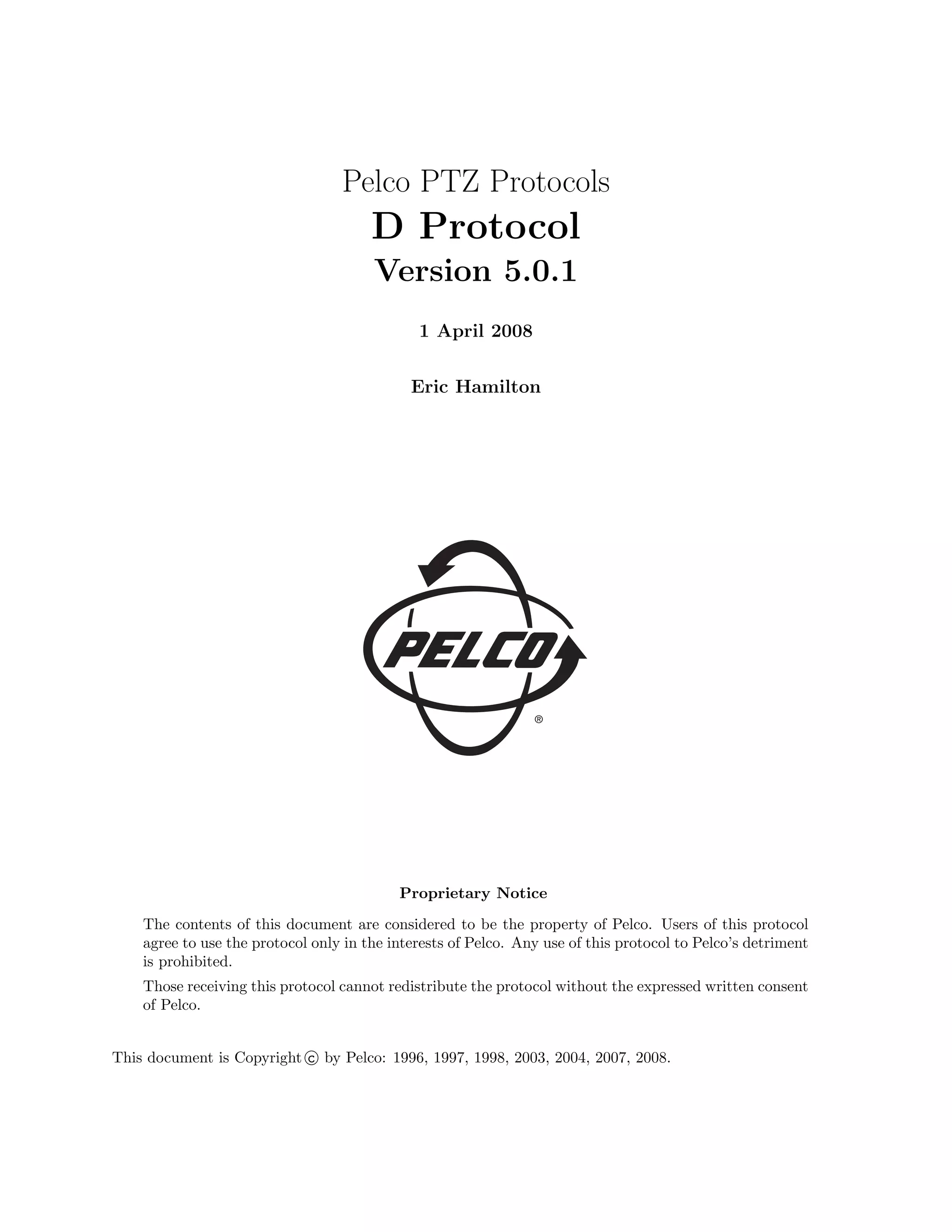
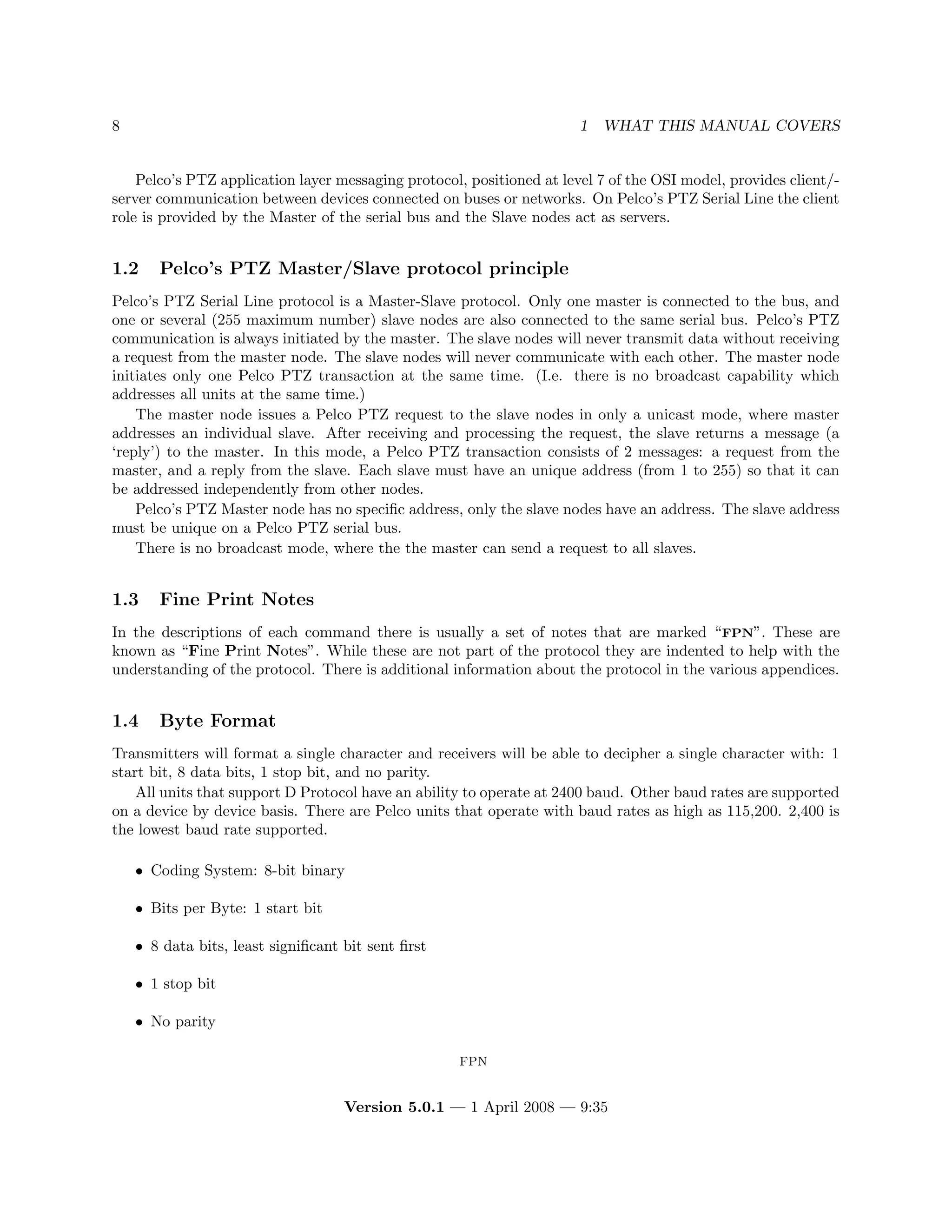
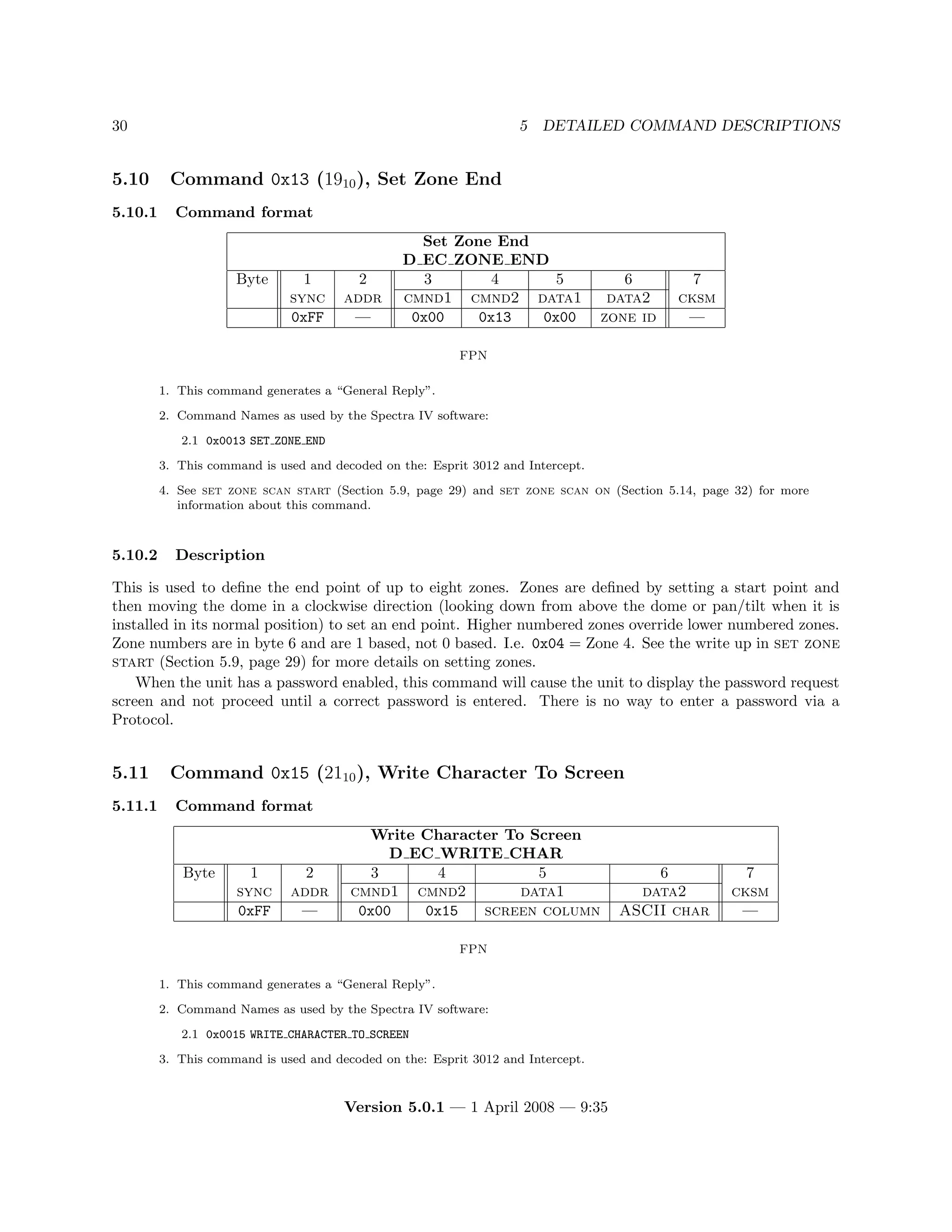
5.9 Command 0x11 (1710), Set Zone Start
5.9.1 Command format
Set Zone Start
D EC ZONE START
Byte 1 2 3 4 5 6 7
sync addr cmnd1 cmnd2 data1 data2 cksm
0xFF — 0x00 0x11 0x00 zone id —
FPN
1. This command generates a “General Reply”.
2. Command Names as used by the Spectra IV software:
2.1 0x0011 SET ZONE START
3. This command is used and decoded on the: Esprit 3012 and Intercept.
4. See zone scan on (Section 5.14, page 32) for more information about this command.
5.9.2 Description
This command is used to define the start point of up to eight zones (zone id). Zones are defined by setting
a start point and then moving the dome in a clockwise direction (looking down from above the dome or
pan/tilt when it is installed in its normal position) to set an end point. Higher numbered zones override
lower numbered zones. Zone numbers are in byte 6 (zone id) and are 1 based, not 0 based. I.e. 0x03 =
Zone 3.
When the unit has a password enabled, this command will cause the unit to display the password request
screen and not proceed until a correct password is entered. There is no way to directly enter a password via
a Protocol.
FPN
5.9.3 Zones
When a set zone start command (Section 5.9, page 29) is received, the current pan position is saved as the start
position for the zone number specified in the command. If the zone was previously defined the end position is
invalidated and the new start position is set. Also whatever is displayed on the Zone label (i.e. columns 0 → 19 of
write character to screen command 0x15, 2110 (Section 5.11, page 30) though not displayed directly on some systems)
on the logical first video line is saved as the zone label. When a set zone end command (Section 5.10, page 30) is
received, the monitor is unlocked How was the monitor locked?[-DGS], and the current pan position is saved as the
end position for the zone number specified (zone id) in the command.
Zones extend from the start point clockwise to the end point. This means that if a zone start point is set, the Spectra
is panned slightly clockwise, and the zone end point is set, the zone will be small. But if the Spectra is panned
slightly counterclockwise between the start and end points, the zone will be almost all the way around the pan circle.
A zone may not be specified that is 360o in size. Starting with the Spectra III the end and start points of the same
zone may not be within 1o of each other. On earlier models the start/end points had to be at least 10o apart.
There are commands to turn set zone scan on (Section 5.14, page 32) and set zone scan off (Section 5.15,
page 34). If zone scan has been turned on, during normal pan/tilt operation the current pan position is continuously
read. If the current position is within a zone, the label for that zone is displayed on the logical first video line. If
the current position is not within any zone, the line is cleared. If the current position is within more than one zone,
the label for the highest-numbered zone will be displayed.
Note
For units previous to Spectra III set zone scan off (Section 5.15, page 34) must be sent off before this
command is received or the zone programming will not work correctly.
Spectra III and Spectra IV does not require Zone Scan to be off to operate properly.
Version 5.0.1 — 1 April 2008 — 9:35](https://image.slidesharecdn.com/pelco-ptz-protocols-d-protocol-revision-5-220310063747/75/Pelco-ptz-protocols-d-protocol-revision-5-0-1-29-2048.jpg)


![86 C INTERPRETING PAN D READOUT REPLIES
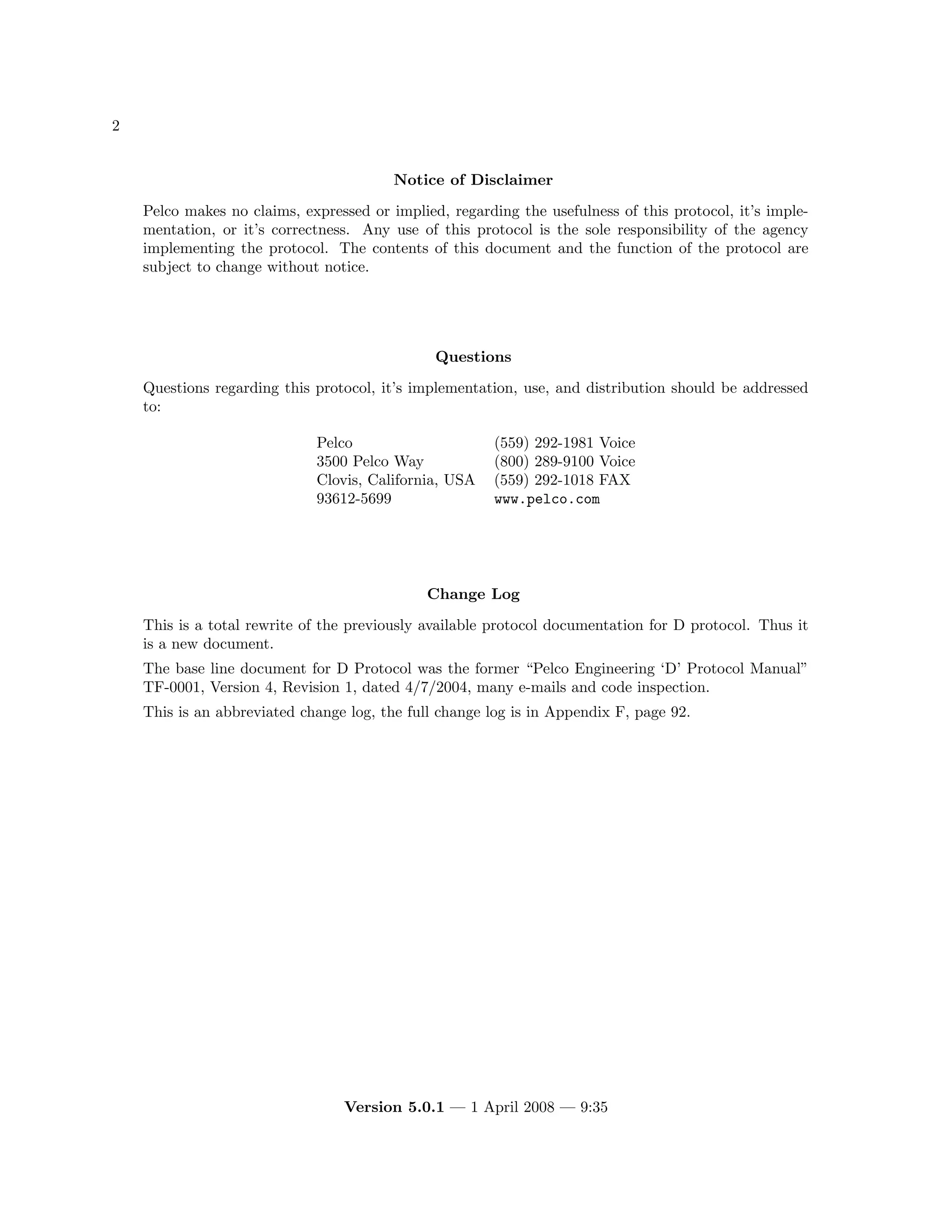
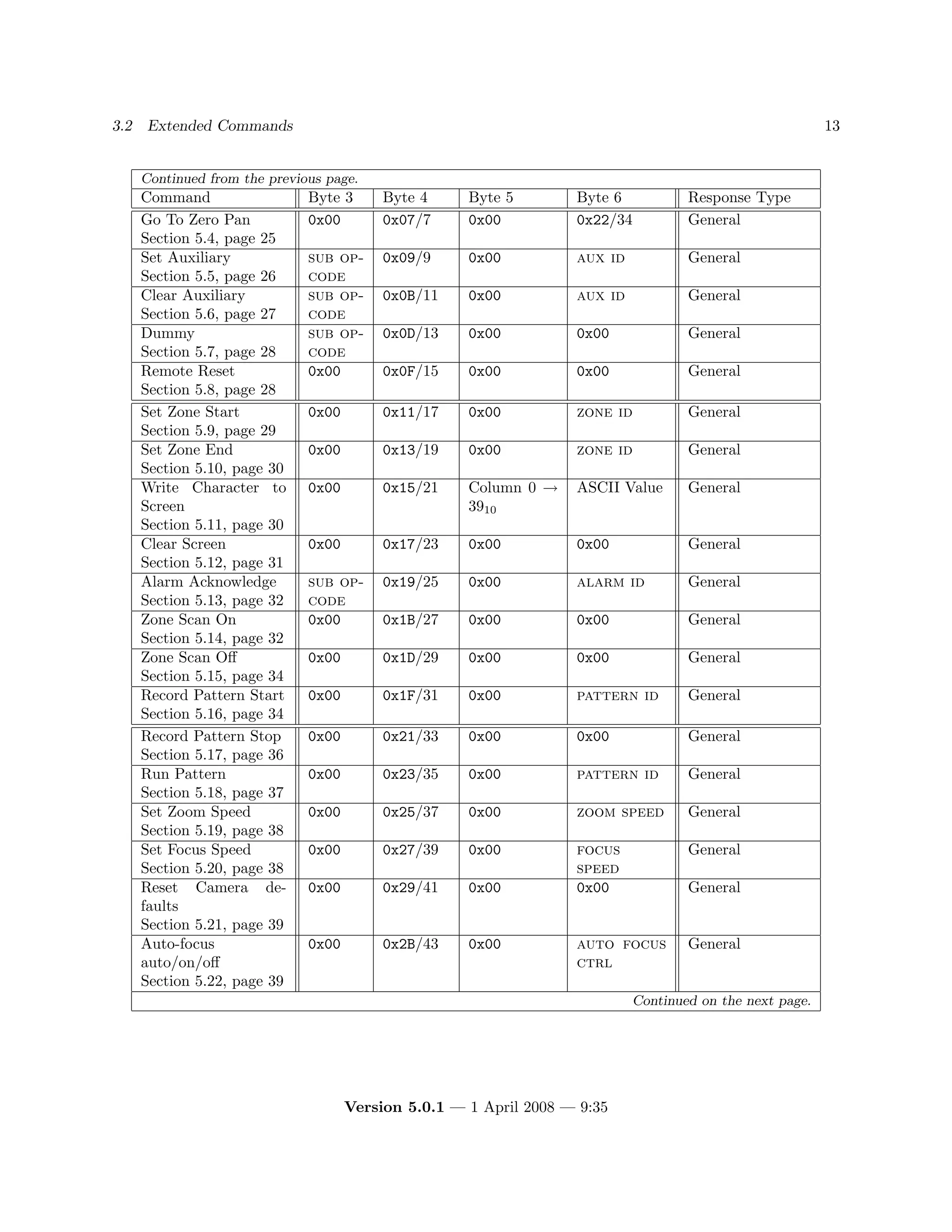
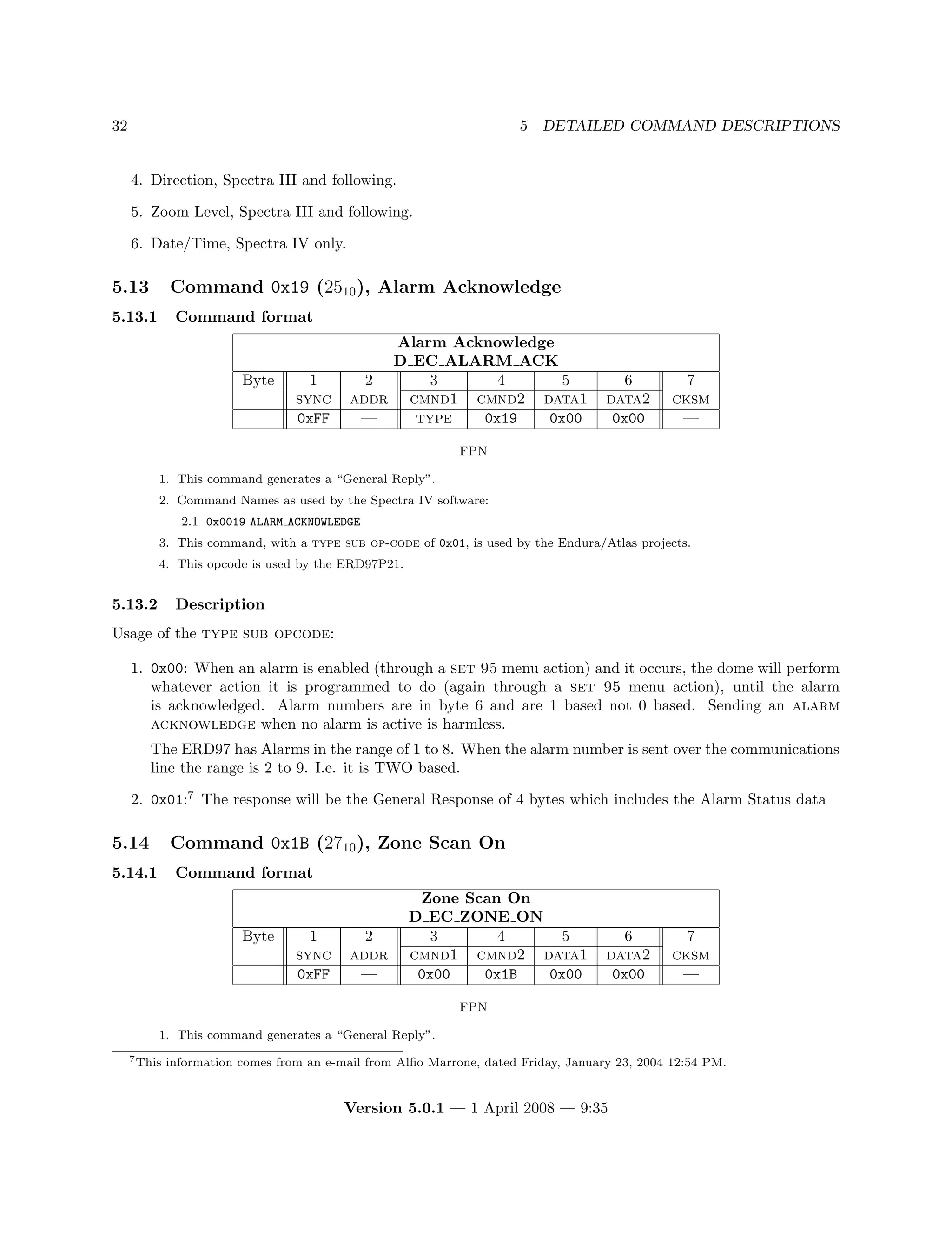
5.1 SCheckSumD()
5.2 GetDReply()
6. The results are in two unsigned chars:
6.1 HpanU this is the upper half of the pan angle when modified by the Set Azimuth Zero value.
6.2 HpanL this is the lower half of the pan angle when modified by the Set Azimuth Zero value.
// Get pan angle offset from zero
SDcmnd1 = D_ECS_EVEREST_AZIMUTH_ZERO_OFFSET_QRY;
SDcmnd2 = D_EC_EVEREST; // This is an Everest op-code
SCheckSumD(YES_REPLY);
GetDReply(D_EC_EXTENDED_REPLY_LENGTH); // Put it in the reply buffer
HR_offset = ((DReply[DREPLY_DATA1]*256) + DReply[DREPLY_DATA2]);
// Get pan angle SDcmnd1, SDdata1 and SData2 don’t change anymore
SDcmnd1 = 0x00;
SDcmnd2 = D_EC_QUERY_PAN; // What is the current azimuth reading
SCheckSumD(YES_REPLY);
GetDReply(D_EC_EXTENDED_REPLY_LENGTH); // Put it in the reply buffer
// Pan angle comes in in two bytes as degrees times 100 "hungrees"
// Value has to be rounded (i.e. that is why there is a "+ 50" here)
//
// The pan angle reported by an D_EC_QUERY_PAN command is not
// offset by the D_EC_SET_ZERO command. But the on screen display
// is. So here we have to modify the reported output by the
// changed pan offset value.
//
// If D_EC_SET_ZERO has been used to set pan zero to 25 degrees,
// and the on-screen display is now reading 50 degrees in pan,
// then the reply from a D_EC_QUERY_PAN command will be 75 degrees.
// In general we should have the angle reported to the outside
// world match what is seen on the screen. Thus there is logic to
// request the actual offset value and to use that in modifying
// the reported value so that it matches the on-screen value.
//
HR_temp = ((DReply[DREPLY_DATA1]*256) + DReply[DREPLY_DATA2]);
HR_temp -= HR_offset; // Get difference of real vs display
if (HR_temp < 0) // Too small
{
HR_temp += 36000; // Yep, let it wrap up
}
HR_temp += 50; // Round
HR_temp /= 100; // Convert from hungrees to decimal
HpanU = (unsigned char) (HR_temp/256);
HpanL = HR_temp & 0xFF;
Version 5.0.1 — 1 April 2008 — 9:35](https://image.slidesharecdn.com/pelco-ptz-protocols-d-protocol-revision-5-220310063747/75/Pelco-ptz-protocols-d-protocol-revision-5-0-1-86-2048.jpg)


![E.1 IR Cut Filter 91
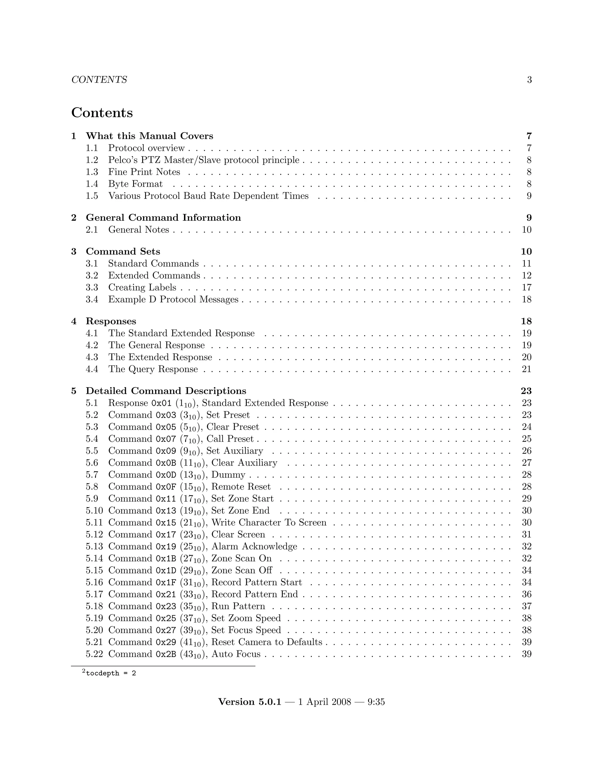
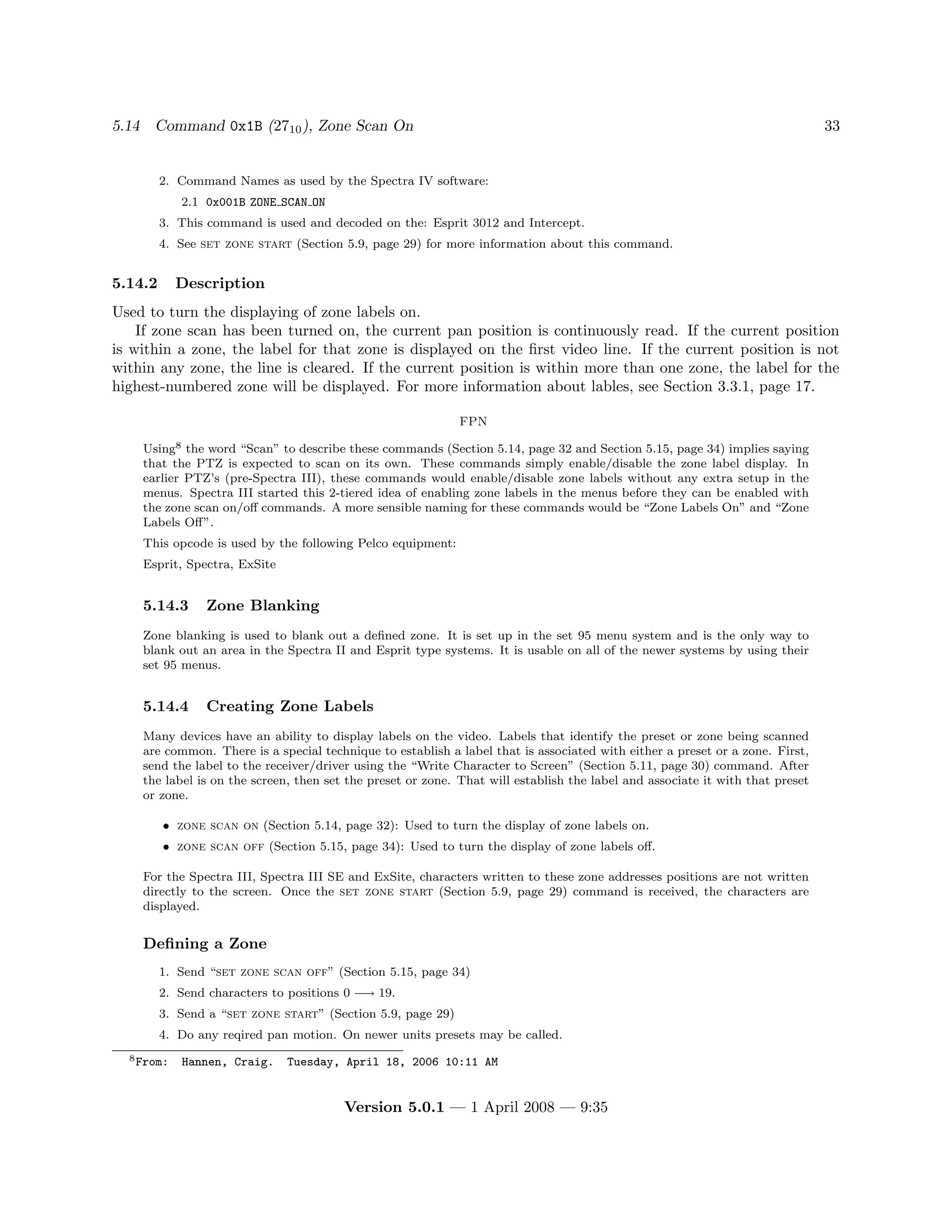
|
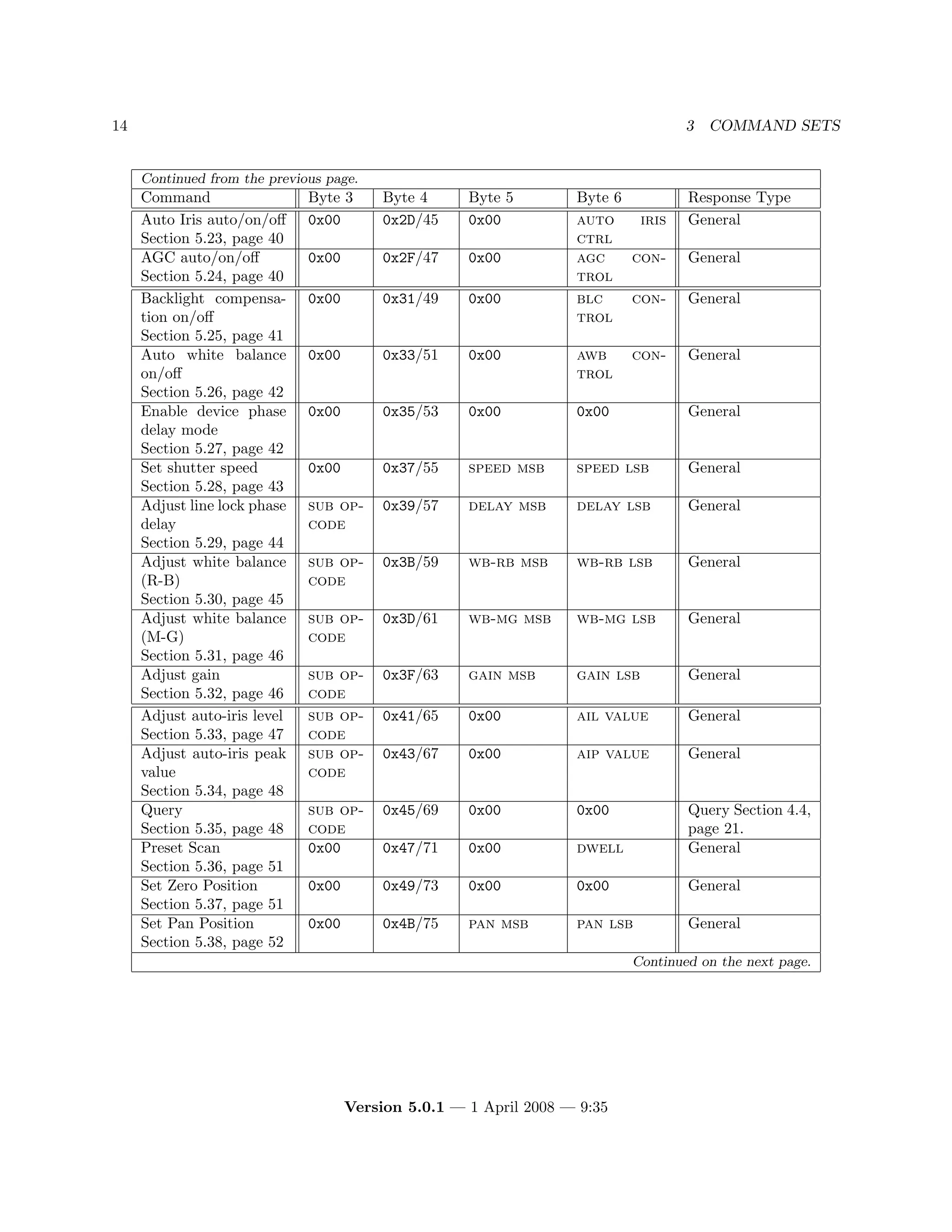
|--IR CUT FILTER --- Set to "OFF" for manual control
Once the camera is set to “OFF” for IR cut filter control, Preset 89 can be used to switch the cut filter
out and put the camera into black and white mode. Preset 88 puts the IR cut filter back in for normal color
operation. If the “noise” artifacts are no longer present in the same scene [i.e. we don’t now have black
and white image artifacts] we would then be able to deduct that the artifacts are coming from the color
properties....
Version 5.0.1 — 1 April 2008 — 9:35](https://image.slidesharecdn.com/pelco-ptz-protocols-d-protocol-revision-5-220310063747/75/Pelco-ptz-protocols-d-protocol-revision-5-0-1-91-2048.jpg)


This document outlines Pelco's proprietary D Protocol version 5.0.1 for PTZ (pan-tilt-zoom) cameras, detailing implementation, use, and command sets. It includes a disclaimer of responsibility for its correctness and changes made since the previous version, along with a comprehensive change log. Users must adhere to copyright provisions and must not redistribute the protocol without permission from Pelco.


