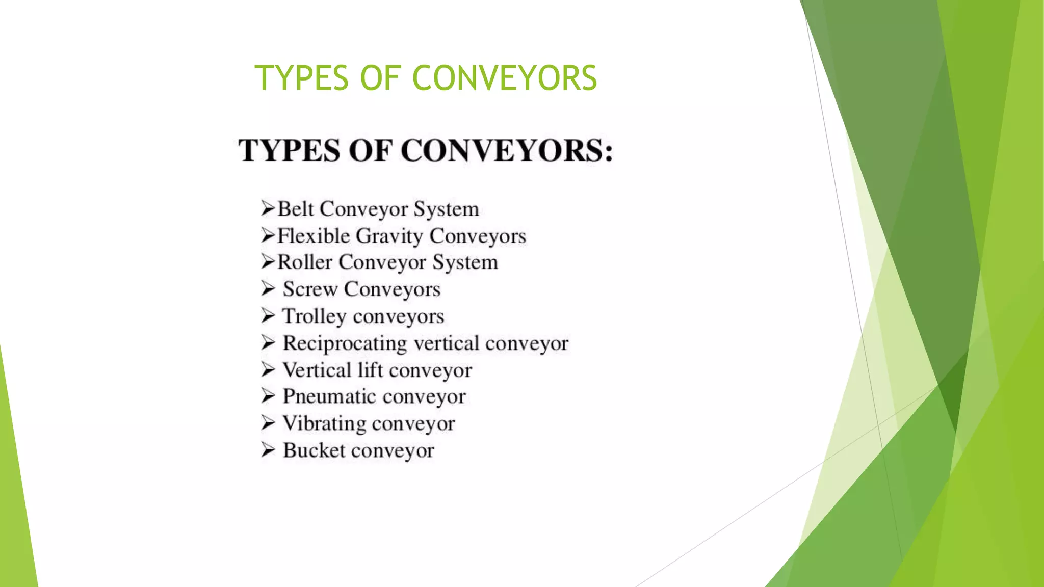
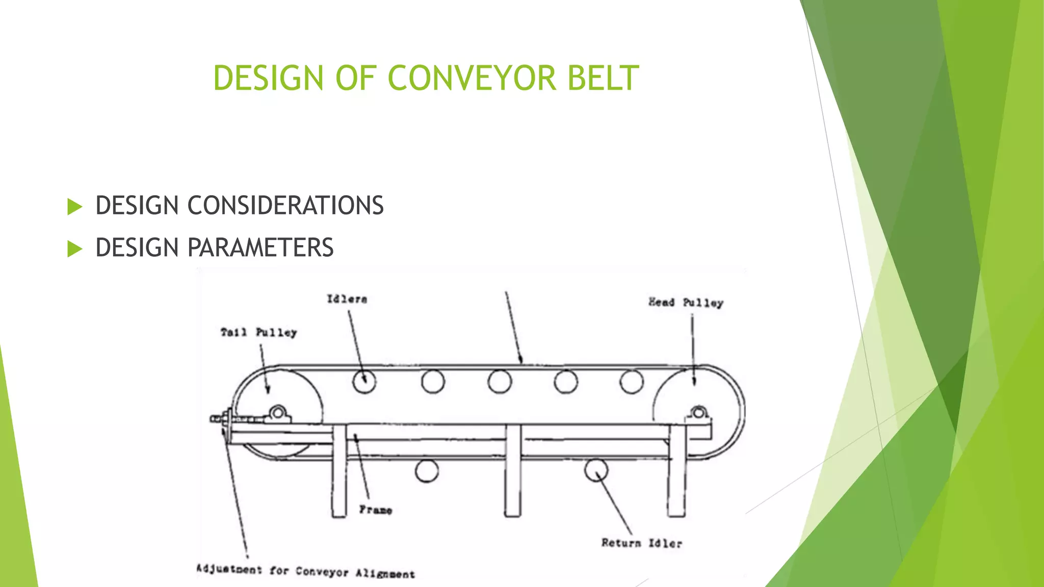
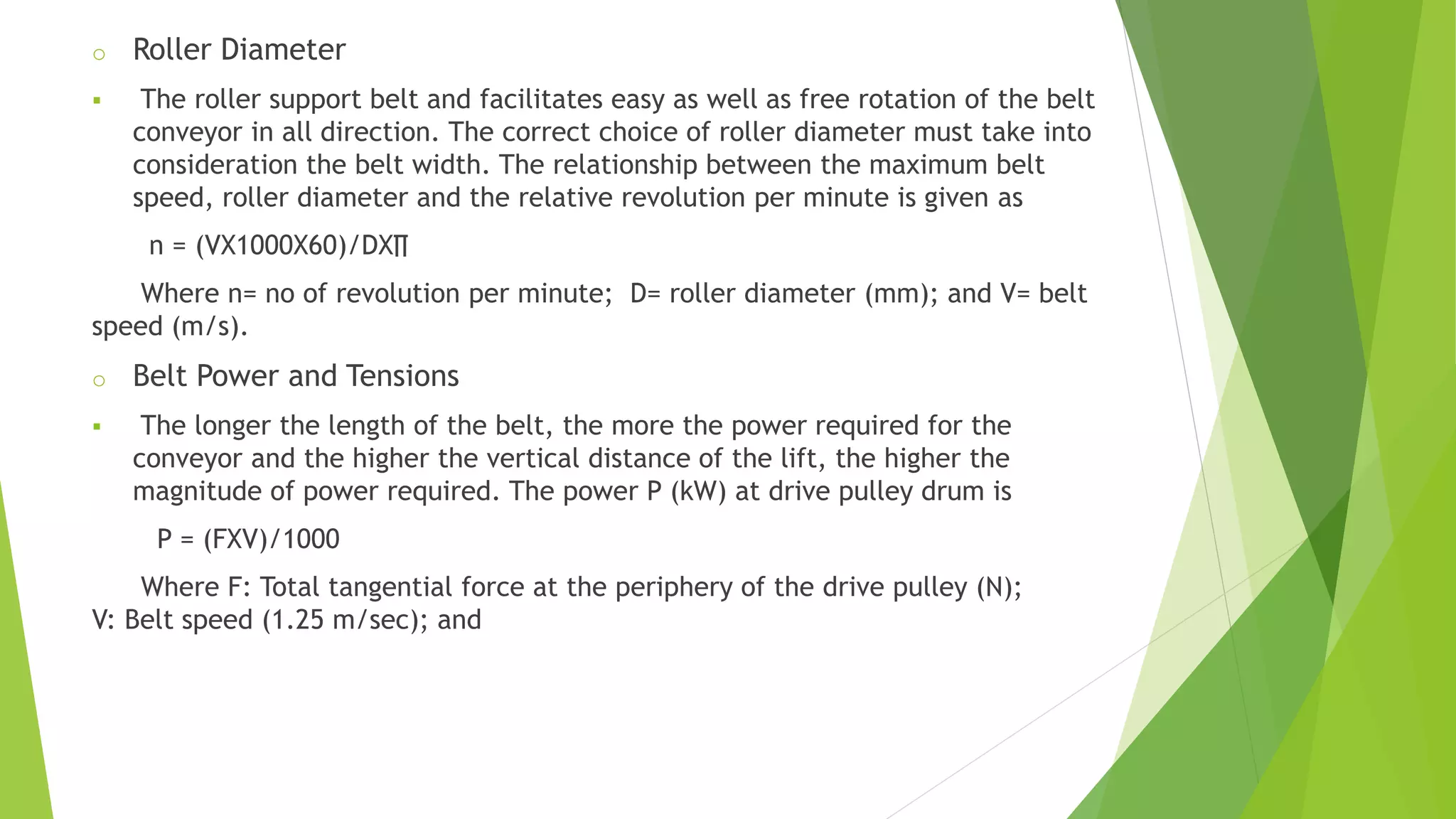
DESIGN OF BELT CONVEYOR SYSTEM
Prepared by:
ANKIT KUMAR
Dept of mechanical engineering
WBUT UNIVERSITY (WEST BENGAL)
INTRODUCTION
 A conveyor system is a common piece of mechanical handling equipment that
moves materials from one location to another. Conveyors are especially useful
in applications involving the transportation of heavy or bulky materials.
Conveyor systems allow quick and efficient transportation for a wide variety
of materials, which make them very popular in the material
handling and packaging industries.
 A conveyor belt is the carrying medium of a belt conveyor system (often
shortened to belt conveyor).
TYPES OF CONVEYORS
DESIGN OF CONVEYOR BELT
 DESIGN CONSIDERATIONS
 DESIGN PARAMETERS
 DESIGN CONSIDERATIONS
o Designing the system for continuous flow of material (idle time should
be zero).
o Going in for standard equipment which ensures low investment and
flexibility.
o Incorporating gravity flow in material flow system and
o Ensuring that the ratio of the dead weight to the payload of material
handling equipment is minimum.
 DESIGN PARAMETERS
o Belt Dimension,Capacity and Speed
o Roller Diameter
o Belt Power and Tensions
o Idler Spacing
o Pulley Diameter
o Motor
o Shaft Design
o Control
o Belt Dimension,Capacity and Speed
 The diameter of the driver and driven pulley is determined by the type and
dimension of conveyor belting. The diameter of the pulley must be designed
such that it does not place undue stress on the belt. The length of a belt
conveyor in metres is the length from the centre of pulley parallel to belt
line. Belt length is dependent on both the pulley diameters and centre
distances.
 Capacity is the product of speed and belt cross sectional area. Generally, belt
capacity B.C(kg/sec) is given as:
B.C =3.6A V ρ Where: A= belt sectional area (m2); ρ = material density
(kg/m3); and V= belt speed (m/s).
o Roller Diameter
 The roller support belt and facilitates easy as well as free rotation of the belt
conveyor in all direction. The correct choice of roller diameter must take into
consideration the belt width. The relationship between the maximum belt
speed, roller diameter and the relative revolution per minute is given as
n = (VX1000X60)/DX∏
Where n= no of revolution per minute; D= roller diameter (mm); and V= belt
speed (m/s).
o Belt Power and Tensions
 The longer the length of the belt, the more the power required for the
conveyor and the higher the vertical distance of the lift, the higher the
magnitude of power required. The power P (kW) at drive pulley drum is
P = (FXV)/1000
Where F: Total tangential force at the periphery of the drive pulley (N);
V: Belt speed (1.25 m/sec); and
 Power required for the conveyor to produce lift can also be calculated as:
P = (C X L X 3.5)/1000
Where: P= power required for conveyor (kW); C= conveyor capacity (355
tonnes/hr) = (98.6 kg/sec); and L=Lift (10 m) P=3.7 kW.
 Belt tension at steady state is given as:
Tss=1.37XfXLXg(2XMi+(2XMb+Mm)cosθ) + HXgXMm
Where: Tss=Belt tension at steady state (N); f= Coefficient of friction (0.02)
L=Conveyor length (100 m); (Conveyor belt is approximately half of the total belt
length) g=Acceleration due to gravity (9.81 m/sec2); Mi=Load due to the idlers
(570 kg); Mb=Load due to belt (577.5 kg); Mm=Load due to conveyed materials
(78.88 kg); θ = Inclination angle of the conveyor (100); and H=Vertical height of
the conveyor (10 m). Tss= 71 KN
 During the start of the conveyor system, the tension in the belt will be much
higher than the steady state. The belt tension while starting is
Ts = Tss X Ks
Where: Ts= Belt tension while starting (N); Tss=Belt tension at the steady
state (71KN); and KS=Start up factor (1.08). Ts=76.68 KN
o Idler Spacing
 Idlers are installed at graduated spacing to ensure that the sag as a result of
load varies inversely with the tension in the belt.
 An idler spacing of 1.0 m is recommended for a belt conveyor system
conveying a material of 1500kg/m3 and on a belt width of 1200 mm.
o Pulley Diameter
 Pulleys are manufactured in a wide range of sizes. The selection of pulley
takes into account the wrap angle (180), belt speed (1.5 m/sec), method of
belt strain, belt tension T, belt width (1200 mm) and type of splice of the
conveyor belt.
 Pulley wraps length at terminals= 2 X Π X D
o Motor
 The minimum motor power for sizing of the motor is
Pmin = Pp / η
Where: Pmin=Minimum motor power (kW); Pp=Power at drive pulley (3.62
kW); and η : Efficiency of the reduction gear (0.9) Pm=4.022 kW.
 To determine the motor horse power hp :
hpmin = Hpreq / η
Where
Hpreq = Hpe + Hpm + Hpj
Where
Hpe=Horse power required to drive the conveyor empty, Hpm= Horse power
required to move material horizontally, Hpj= Horse power required to elevate
material.
o Shaft Design
 Shaft design consists primarily of determination of the correct shaft diameter
that will ensure satisfactory rigidity and strength when the shaft is
transmitting motion under different operating and loading conditions. The
values of belt width and pulley diameter helps in selecting the size of shaft
diameter from different conveyors hand book.
o Control
 Compact Programmable Controllers otherwise known as application
controllers can be used for the control of the system. These controllers can e
used for time control and supervisory functions such as: conveyor speed
control, speed control of individual drives, speed and belt slip control, load
equilibration between two driving drum and speed difference control
between two motors on one driving drum.
LIMITATION AND CONCLUSION
 The construction of a belt conveyor system requires high capital base. This is
a major constraint that limits this work to design only and as such
performance evaluation cannot be carried out on the belt conveyor system.
However, the research work provides design data for development of belt
conveyor system for industrial uses.
 The belt conveyor system is designed with high degree of automation,
loading, movement and unloading efficiency. It is also very flexible, safe, with
low initial, operational and maintenance cost while eliminating repetitive
short distance movement in the manufacturing industry.
THANK YOU.....

Design of Belt conveyor system

  • 1.
    DESIGN OF BELTCONVEYOR SYSTEM Prepared by: ANKIT KUMAR Dept of mechanical engineering WBUT UNIVERSITY (WEST BENGAL)
  • 2.
    INTRODUCTION  A conveyorsystem is a common piece of mechanical handling equipment that moves materials from one location to another. Conveyors are especially useful in applications involving the transportation of heavy or bulky materials. Conveyor systems allow quick and efficient transportation for a wide variety of materials, which make them very popular in the material handling and packaging industries.  A conveyor belt is the carrying medium of a belt conveyor system (often shortened to belt conveyor).
  • 3.
  • 4.
    DESIGN OF CONVEYORBELT  DESIGN CONSIDERATIONS  DESIGN PARAMETERS
  • 5.
     DESIGN CONSIDERATIONS oDesigning the system for continuous flow of material (idle time should be zero). o Going in for standard equipment which ensures low investment and flexibility. o Incorporating gravity flow in material flow system and o Ensuring that the ratio of the dead weight to the payload of material handling equipment is minimum.
  • 6.
     DESIGN PARAMETERS oBelt Dimension,Capacity and Speed o Roller Diameter o Belt Power and Tensions o Idler Spacing o Pulley Diameter o Motor o Shaft Design o Control
  • 7.
    o Belt Dimension,Capacityand Speed  The diameter of the driver and driven pulley is determined by the type and dimension of conveyor belting. The diameter of the pulley must be designed such that it does not place undue stress on the belt. The length of a belt conveyor in metres is the length from the centre of pulley parallel to belt line. Belt length is dependent on both the pulley diameters and centre distances.  Capacity is the product of speed and belt cross sectional area. Generally, belt capacity B.C(kg/sec) is given as: B.C =3.6A V ρ Where: A= belt sectional area (m2); ρ = material density (kg/m3); and V= belt speed (m/s).
  • 8.
    o Roller Diameter The roller support belt and facilitates easy as well as free rotation of the belt conveyor in all direction. The correct choice of roller diameter must take into consideration the belt width. The relationship between the maximum belt speed, roller diameter and the relative revolution per minute is given as n = (VX1000X60)/DX∏ Where n= no of revolution per minute; D= roller diameter (mm); and V= belt speed (m/s). o Belt Power and Tensions  The longer the length of the belt, the more the power required for the conveyor and the higher the vertical distance of the lift, the higher the magnitude of power required. The power P (kW) at drive pulley drum is P = (FXV)/1000 Where F: Total tangential force at the periphery of the drive pulley (N); V: Belt speed (1.25 m/sec); and
  • 9.
     Power requiredfor the conveyor to produce lift can also be calculated as: P = (C X L X 3.5)/1000 Where: P= power required for conveyor (kW); C= conveyor capacity (355 tonnes/hr) = (98.6 kg/sec); and L=Lift (10 m) P=3.7 kW.  Belt tension at steady state is given as: Tss=1.37XfXLXg(2XMi+(2XMb+Mm)cosθ) + HXgXMm Where: Tss=Belt tension at steady state (N); f= Coefficient of friction (0.02) L=Conveyor length (100 m); (Conveyor belt is approximately half of the total belt length) g=Acceleration due to gravity (9.81 m/sec2); Mi=Load due to the idlers (570 kg); Mb=Load due to belt (577.5 kg); Mm=Load due to conveyed materials (78.88 kg); θ = Inclination angle of the conveyor (100); and H=Vertical height of the conveyor (10 m). Tss= 71 KN
  • 10.
     During thestart of the conveyor system, the tension in the belt will be much higher than the steady state. The belt tension while starting is Ts = Tss X Ks Where: Ts= Belt tension while starting (N); Tss=Belt tension at the steady state (71KN); and KS=Start up factor (1.08). Ts=76.68 KN o Idler Spacing  Idlers are installed at graduated spacing to ensure that the sag as a result of load varies inversely with the tension in the belt.  An idler spacing of 1.0 m is recommended for a belt conveyor system conveying a material of 1500kg/m3 and on a belt width of 1200 mm. o Pulley Diameter  Pulleys are manufactured in a wide range of sizes. The selection of pulley takes into account the wrap angle (180), belt speed (1.5 m/sec), method of belt strain, belt tension T, belt width (1200 mm) and type of splice of the conveyor belt.  Pulley wraps length at terminals= 2 X Π X D
  • 11.
    o Motor  Theminimum motor power for sizing of the motor is Pmin = Pp / η Where: Pmin=Minimum motor power (kW); Pp=Power at drive pulley (3.62 kW); and η : Efficiency of the reduction gear (0.9) Pm=4.022 kW.  To determine the motor horse power hp : hpmin = Hpreq / η Where Hpreq = Hpe + Hpm + Hpj Where Hpe=Horse power required to drive the conveyor empty, Hpm= Horse power required to move material horizontally, Hpj= Horse power required to elevate material.
  • 12.
    o Shaft Design Shaft design consists primarily of determination of the correct shaft diameter that will ensure satisfactory rigidity and strength when the shaft is transmitting motion under different operating and loading conditions. The values of belt width and pulley diameter helps in selecting the size of shaft diameter from different conveyors hand book. o Control  Compact Programmable Controllers otherwise known as application controllers can be used for the control of the system. These controllers can e used for time control and supervisory functions such as: conveyor speed control, speed control of individual drives, speed and belt slip control, load equilibration between two driving drum and speed difference control between two motors on one driving drum.
  • 13.
    LIMITATION AND CONCLUSION The construction of a belt conveyor system requires high capital base. This is a major constraint that limits this work to design only and as such performance evaluation cannot be carried out on the belt conveyor system. However, the research work provides design data for development of belt conveyor system for industrial uses.  The belt conveyor system is designed with high degree of automation, loading, movement and unloading efficiency. It is also very flexible, safe, with low initial, operational and maintenance cost while eliminating repetitive short distance movement in the manufacturing industry.
  • 14.